EP0573791A1 - Méthode de câblage de places de raccordement des appareils électriques ou des éléments d'unités électriques - Google Patents
Méthode de câblage de places de raccordement des appareils électriques ou des éléments d'unités électriques Download PDFInfo
- Publication number
- EP0573791A1 EP0573791A1 EP93107493A EP93107493A EP0573791A1 EP 0573791 A1 EP0573791 A1 EP 0573791A1 EP 93107493 A EP93107493 A EP 93107493A EP 93107493 A EP93107493 A EP 93107493A EP 0573791 A1 EP0573791 A1 EP 0573791A1
- Authority
- EP
- European Patent Office
- Prior art keywords
- line
- laying
- connection point
- laying means
- housing
- Prior art date
- Legal status (The legal status is an assumption and is not a legal conclusion. Google has not performed a legal analysis and makes no representation as to the accuracy of the status listed.)
- Granted
Links
Images


Classifications
-
- H—ELECTRICITY
- H01—ELECTRIC ELEMENTS
- H01R—ELECTRICALLY-CONDUCTIVE CONNECTIONS; STRUCTURAL ASSOCIATIONS OF A PLURALITY OF MUTUALLY-INSULATED ELECTRICAL CONNECTING ELEMENTS; COUPLING DEVICES; CURRENT COLLECTORS
- H01R43/00—Apparatus or processes specially adapted for manufacturing, assembling, maintaining, or repairing of line connectors or current collectors or for joining electric conductors
- H01R43/01—Apparatus or processes specially adapted for manufacturing, assembling, maintaining, or repairing of line connectors or current collectors or for joining electric conductors for connecting unstripped conductors to contact members having insulation cutting edges
-
- H—ELECTRICITY
- H01—ELECTRIC ELEMENTS
- H01R—ELECTRICALLY-CONDUCTIVE CONNECTIONS; STRUCTURAL ASSOCIATIONS OF A PLURALITY OF MUTUALLY-INSULATED ELECTRICAL CONNECTING ELEMENTS; COUPLING DEVICES; CURRENT COLLECTORS
- H01R43/00—Apparatus or processes specially adapted for manufacturing, assembling, maintaining, or repairing of line connectors or current collectors or for joining electric conductors
- H01R43/28—Apparatus or processes specially adapted for manufacturing, assembling, maintaining, or repairing of line connectors or current collectors or for joining electric conductors for wire processing before connecting to contact members, not provided for in groups H01R43/02 - H01R43/26
-
- H—ELECTRICITY
- H05—ELECTRIC TECHNIQUES NOT OTHERWISE PROVIDED FOR
- H05K—PRINTED CIRCUITS; CASINGS OR CONSTRUCTIONAL DETAILS OF ELECTRIC APPARATUS; MANUFACTURE OF ASSEMBLAGES OF ELECTRICAL COMPONENTS
- H05K13/00—Apparatus or processes specially adapted for manufacturing or adjusting assemblages of electric components
- H05K13/06—Wiring by machine
-
- H—ELECTRICITY
- H01—ELECTRIC ELEMENTS
- H01R—ELECTRICALLY-CONDUCTIVE CONNECTIONS; STRUCTURAL ASSOCIATIONS OF A PLURALITY OF MUTUALLY-INSULATED ELECTRICAL CONNECTING ELEMENTS; COUPLING DEVICES; CURRENT COLLECTORS
- H01R4/00—Electrically-conductive connections between two or more conductive members in direct contact, i.e. touching one another; Means for effecting or maintaining such contact; Electrically-conductive connections having two or more spaced connecting locations for conductors and using contact members penetrating insulation
- H01R4/24—Connections using contact members penetrating or cutting insulation or cable strands
- H01R4/2416—Connections using contact members penetrating or cutting insulation or cable strands the contact members having insulation-cutting edges, e.g. of tuning fork type
- H01R4/242—Connections using contact members penetrating or cutting insulation or cable strands the contact members having insulation-cutting edges, e.g. of tuning fork type the contact members being plates having a single slot
- H01R4/2425—Flat plates, e.g. multi-layered flat plates
- H01R4/2429—Flat plates, e.g. multi-layered flat plates mounted in an insulating base
-
- Y—GENERAL TAGGING OF NEW TECHNOLOGICAL DEVELOPMENTS; GENERAL TAGGING OF CROSS-SECTIONAL TECHNOLOGIES SPANNING OVER SEVERAL SECTIONS OF THE IPC; TECHNICAL SUBJECTS COVERED BY FORMER USPC CROSS-REFERENCE ART COLLECTIONS [XRACs] AND DIGESTS
- Y10—TECHNICAL SUBJECTS COVERED BY FORMER USPC
- Y10T—TECHNICAL SUBJECTS COVERED BY FORMER US CLASSIFICATION
- Y10T29/00—Metal working
- Y10T29/49—Method of mechanical manufacture
- Y10T29/49002—Electrical device making
- Y10T29/49117—Conductor or circuit manufacturing
- Y10T29/49124—On flat or curved insulated base, e.g., printed circuit, etc.
- Y10T29/49155—Manufacturing circuit on or in base
- Y10T29/49162—Manufacturing circuit on or in base by using wire as conductive path
-
- Y—GENERAL TAGGING OF NEW TECHNOLOGICAL DEVELOPMENTS; GENERAL TAGGING OF CROSS-SECTIONAL TECHNOLOGIES SPANNING OVER SEVERAL SECTIONS OF THE IPC; TECHNICAL SUBJECTS COVERED BY FORMER USPC CROSS-REFERENCE ART COLLECTIONS [XRACs] AND DIGESTS
- Y10—TECHNICAL SUBJECTS COVERED BY FORMER USPC
- Y10T—TECHNICAL SUBJECTS COVERED BY FORMER US CLASSIFICATION
- Y10T29/00—Metal working
- Y10T29/49—Method of mechanical manufacture
- Y10T29/49002—Electrical device making
- Y10T29/49117—Conductor or circuit manufacturing
- Y10T29/49174—Assembling terminal to elongated conductor
- Y10T29/49181—Assembling terminal to elongated conductor by deforming
-
- Y—GENERAL TAGGING OF NEW TECHNOLOGICAL DEVELOPMENTS; GENERAL TAGGING OF CROSS-SECTIONAL TECHNOLOGIES SPANNING OVER SEVERAL SECTIONS OF THE IPC; TECHNICAL SUBJECTS COVERED BY FORMER USPC CROSS-REFERENCE ART COLLECTIONS [XRACs] AND DIGESTS
- Y10—TECHNICAL SUBJECTS COVERED BY FORMER USPC
- Y10T—TECHNICAL SUBJECTS COVERED BY FORMER US CLASSIFICATION
- Y10T29/00—Metal working
- Y10T29/53—Means to assemble or disassemble
- Y10T29/5313—Means to assemble electrical device
- Y10T29/532—Conductor
- Y10T29/53243—Multiple, independent conductors
Definitions
- the procedure can also be such that the line laying means are arranged in a stationary manner or on a positioning device which only gives them a positioning movement, while the preassembled electrical device or component part is moved by means of a transport means which can be moved relative to the line laying means.
- the means of transport is also connected to a programmable control unit, which allows the corresponding routing routes for the directly wired lines to be achieved fully automatically. The work result is therefore the same. Which of the two procedures in the The choice of individual case depends, among other things, on the type of device or module element to be wired.
- the relative movement between the preassembled electrical device or assembly element and the line laying means generated in the above-mentioned manner for direct wiring can be chosen as a function of the local conditions within the device or assembly element, with curvilinear installation paths also being possible. As a rule, however, it is expedient if this relative movement is essentially straight, at least in sections, so that straight laying paths result at least in sections.
- the formation of the contacting zones at the individual connection points must be carried out in a manner suitable for automation, ie the line laying means must be able, after being positioned at the respective connection point, to insert the line fully automatically into the respective contacting zone and to contact it.
- this requirement can be met in a particularly simple manner by using contacting zones with contact means which act according to the principle of insulation displacement technology, the line being pressed into the contact means by the line-laying means while producing the electrical contact.
- the insulation displacement technology results in a very high quality electrical connection of the electrical conductor of the line to be connected with the contact means, because it causes a flat, gas-tight contact in the manner of a cold welding.
- the new wiring method is carried out with appropriately designed line routing means which allow the individual functions required for the work process to be carried out.
- An embodiment of such line laying means which is particularly suitable for this purpose is the subject of patent claim 20, the preamble of which is based on a prior art as given by the line laying tools known from DE-OSen 36 06 059, 36 11 805 and 38 20 636.
- the laying tool contained in the line laying means has, according to the invention, the features of the characterizing part of patent claim 20.
- the insertion slot of the housing at the connection point can be a clamping fixation of a depressed one Have line effecting width, so that it is fixed regardless of the actual contact zone.
- the recess in the housing can also be delimited on both sides by insulation displacement contacts or arranged on one or both sides by an insulation displacement contact.
- the method for direct wiring of electrical devices and assembly elements is described below with reference to the wiring of a rectangular luminaire box 1 shown in FIG. 1 for two rod-shaped gas discharge tubes, which are not illustrated in any more detail.
- the light box is covered by a translucent acrylic glass hood or a reflector, which is clamped in holders 2 and is not shown in the rest.
- the light box is already preassembled insofar as the electrical switching elements required for receiving and operating the gas discharge lamps have been securely fastened, for example screwed on, to the box base 3 according to a predetermined site plan.
- four lamp sockets 4 of a known type are provided in pairs in the vicinity of the box end walls, to which two magnetic ballasts 5 are assigned, which are arranged approximately on the center line of the box bottom 3 on both sides of line insertion openings 6 at equal distances from the box end walls.
- an insulating material base 7, which carries a capacitor 8 is also fastened to the base floor 3 on the center line thereof.
- connection point 10 has a housing 12 made of insulating material of substantially rectangular cross-sectional shape, which is placed on a base part 13 also made of insulating material, so that there is a uniform connecting terminal which at 14 on a punched-out, bent-up tab of a base plate 15 of the ballast 5 is attached.
- the two side walls 16 of the housing 12, which is open towards the top, carry on their inner side two mutually opposite, integrally formed ribs 17 which lie approximately in the middle between the two end faces 18 of the housing 12 and between them a slightly wedge-shaped or parallel-flanked insertion slot 19 (FIG. 6 ) limit, which is widened at its top by insertion bevels 20. In its lower region, the insertion slot is locally somewhat widened at 21 in a part-circular region.
- the housing 12 has a groove-like depression 26 of rectangular cross-sectional shape on both sides of the ribs 17 and thus the insertion slot 19, which opens next to the insertion slot 19 towards the top of the housing 12.
- the two groove-like depressions 26 are arranged in alignment with one another and with the insertion slot 19. You are also limited above by an insertion bevel 27.
- FIGS. 5, 7 show that the depth of the groove-like recesses 26 is greater than that of the insertion slot 19 and that their width 28 is also substantially greater than the width of the insertion slot 19.
- the width and depth of the groove-like depressions 26 and their axial length are dimensioned such that protection against contact is automatically obtained for the cut end of the line. This means that the standardized feeler finger cannot test to the bare cut end in the depth of the associated groove-like recess 26 when testing for safety against contact.
- two mutually aligned groove-like depressions 26 are provided on both sides of the insertion slot 19, the width and depth of which are substantially larger than the diameter of the line to be accommodated. It is also conceivable to omit one of the groove-like depressions 26, which is particularly useful if, as will also be explained below, the line is only laid continuously through the connection point. In individual cases, both groove-like depressions 26 can also be omitted.
- FIG. 4 A top view of a modified embodiment of the housing 12 is shown in FIG. 4: in this embodiment there is only one groove-like depression 26, which is provided in the housing 12a on both sides by a pair of ribs 17 with an insertion slot 19 in between and one with its legs 24 therein projecting contact element 25 is limited.
- the pairs of ribs are each formed flush on the end side of the housing 12a with the side walls 16a and aligned with their insertion slots 19 on the longitudinal axis of the groove-like recess 26.
- connection points 11 arranged on the insulating material base 7 are, as can be seen from FIG. 8, basically the same as the connection points 10. In this respect, reference is therefore made to the explanations relating to FIGS. 2 to 7. The same parts are provided with the same reference symbols.
- connection points 9 of the lamp holders 4 are basically constructed in accordance with the connection points 10 according to FIGS. 2, 3. 9 are therefore Identical parts are again provided with the same reference numerals, reference being made to the explanations for FIGS. 2, 3.
- the arrangement is such that the housing 12 are attached to a mounting base 30 of the respective lamp holder 4 with transverse to the longitudinal direction of the gas discharge lamps to be used and thus the lamp box bottom 3 insertion slots 19 and groove-like depressions 26. Cables to be connected must therefore be pressed into the insertion slot 19 in the lamp holders 4 at right angles to the longitudinal extent of the lamp box 3.
- the industrial robot 33 is assigned a stationary work table 44 with an integrated transport mechanism, indicated by an arrow 45 (FIG. 10), which allows light boxes 1 according to FIG. 1, which are successively preassembled on the horizontal work surface of the work table 44, from an off-standby position at 46 (FIG. 10) in the functional area of the line laying means 31 delimited by the essentially circular trajectory 42, as is indicated by the working position of the light box 1 at 47 illustrated in FIGS. 10, 11. In this working position 47, the light box 1 is clamped in the correct position on the work table 44.
- the associated clamping devices are of a known type; they are not shown in FIGS. 10, 11.
- the line laying means 31 can be brought by the programmable industrial robot 33 to any position within the light box 1 and moved within the light box 1 in any pre-programmed defined way.
- the portal handling device 48 shown in FIG. 12 in which the preassembled light box 1 is clamped in the correct position on a stationary work table 49 on a light box holder 50 and the line laying means 31 are arranged on a carriage 51 which is attached to a portal 52 is freely programmable in the X direction indicated by a double arrow in the longitudinal direction of the lamp box and in a transverse direction, which is also indicated by a double arrow, is supported so that it can be moved across.
- the line laying means 31 are rotatably mounted on the carriage 51 about a vertical axis of rotation 53 (c-axis).
- Each of the movement axes X, Y, c, as well as the stroke axis (z-axis) are assigned their own incremental step drives, which, controlled by a freely programmable control unit, the line laying means 31 within the fixed, pre-assembled luminaire box 31 at any point on the can bring a preprogrammed path.
- the relative movement between the cable laying means 31 and the preassembled luminaire box 1 required for the wiring, ie for wiring the connection points 9, 10, 11 of the preassembled luminaire box 1, can finally also be achieved with the device according to FIG. 13.
- the preassembled light box 1 is clamped on an XY table 54 by means of the light box holder 50, the axes of movement X, Y of which are each indicated by double arrows.
- the line laying means 31 are supported by a positioning device 56 arranged above the XY table 54 on a fixed support 55, which means that the line laying means 31 has a lifting movement in the Z direction (indicated by a double arrow) and can give a rotary movement about the vertical axis 53 (c-axis).
- the XY table 54 and the positioning device 56 are assigned incremental drives for movement in the XY and zc axes, which are controlled by a freely programmable control unit, in such a way that the line laying unit 31 is located at any location within of the light box 1 can be brought in the programmed way.
- the belts 67 each running parallel to one another and at a short distance from one another, are coupled via the belt rollers 66 to an incremental drive which gives them a controlled drive movement which is synchronized with the relative path movement between the preassembled luminaire box 1 and the line laying means 31, which can be generated by the devices according to FIGS. 10 to 13 in the production of the wiring.
- a measuring system upstream of the belt drive for the line 68 which consists of a measuring wheel 70 and a drive roller 71 which is elastically preloaded in the engagement position, makes it possible to measure the exact feed movement of the line 68 independently of the slip occurring between the endless belts 67 of the belt drive, so that a perfect synchronization of the line feed with the movement of the robot 33, the handling device 48 or the XY table 54 is guaranteed.
- a Axis vertically movable pressure member in the form of a slidable Stamp 76 arranged, which can be moved up and down in the interior of the housing 58 via an associated actuator.
- the movement of the stamp 76 is controlled by the control unit as a function of the travel movement of the line laying means 31.
- a sensor 77 coupled with the stamp 76 (FIG.
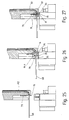
- a cutting knife 79 is mounted on the vertical side surface 60 of the laying finger 59 and can be moved up and down, the associated drive mechanism of which is accommodated in the housing 58 is not shown any further. It can be advanced with the knife edge 80 (FIG. 16) arranged at its lower end from the rest position shown in FIGS. 14, 16, 17 into a working position illustrated in FIG. 27, in which it comes out of the mouth 74 of the conduit channel 62 protruding end of line 68 has cut smoothly.
- the knife edge 80 has crossed the opening of the mouth 74, the underside 81 of the mouth edge of the line guide channel 62 serving as a counter knife, as can be seen easily from FIG. 27, for example.
- position sensors are arranged on the housing 58 in the form of an image processing system 85 with its image recording device 86 above the connection point 10.
- the image processing system 85 contains means for image evaluation, with the aid of which it calculates the positional deviation of the laying finger 59 from the connection point 10 generates a corresponding compensation control signal.
- This signal is processed in the control unit in the sense that the industrial robot 33 - or a positioning system arranged between it and the line laying means 31, similar to the positioning device 56 according to FIG. 13 - carries out the required position tolerance compensation and the laying finger 59 is positioned exactly in the correct position to the connection point 10 positioned.
- the laying finger 59 assumes the position shown in FIG. 16, in which it is precisely aligned above the housing 12 and its groove-like depressions 26.
- the stamp 76 now goes into its lower operating position according to FIG. 17, in which it rests with its pressure surface 78, which is arranged at the bottom of a longitudinal groove, on the line end piece 84 which is advanced correspondingly far out from the mouth 74 of the line guide channel 92 and positions it exactly horizontally. If necessary, the line end piece 84 can still be advanced to the end of the pressure surface 78.
- the laying tool of the line laying means 31 and in particular their laying finger 59 and the punch 76 are simultaneously moved downwards along the vertical Z-axis.
- the horizontal line end piece 84 is pressed through the insertion slot 19 of the housing 12 at the connection point 10 into the insulation displacement slot 23 of the cutting contact 25 until the line piece 84 is locked in the slot widening 21 (FIG. 6).
- an equally large, uniform pressing-in force is exerted on the horizontally held line end piece 84 from the top of the line guide channel 62 and the pressure surface 78 on both sides of the insertion slot 19, so that this cannot evade and a perfect insertion into the contacting zone of the connection point 10 is ensured .
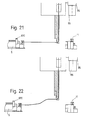
- the laying finger 59 is initially only brought into the vicinity of the connection point 11 in the position according to FIGS. 21 and 22, in which the image processing system 85 is located above the connection point 11 and can detect its spatial position, which can also be inevitable Assembly tolerances of the components may be affected.
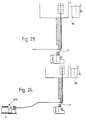
- the image processing system 85 now, similarly to the connection point 10, determines the positional deviation of the laying finger 59 from the connection point 11 and, via the control unit of the industrial robot 33, effects the position tolerance compensation required for the exact positioning of the laying finger 59 to the connection point 11. As soon as this is complete, the parts assume the position according to FIGS. 23 and 24.
- the industrial robot 33 When laying the lines between the connection points 11, 10 (FIGS. 26 and 31), the industrial robot 33 therefore first brings the laying finger 59 in the vicinity of the respective holding element 870 on a preprogrammed path. After the laying finger 59 has been positioned in the manner already described, using the image processing system 85 the stamp 76 goes down and either alone or together with the laying finger 59 presses the line into one of the locking grooves 88. The stamp 76 is then brought back into its end or rest position; the laying finger 59 moves up and is moved to the next-following mounting element 870, where the same process is repeated.
- FIGS. 33, 34 The direct wiring of the preassembled luminaire box 1 carried out by means of the described method steps is illustrated in FIGS. 33, 34 for the two cases that the line 68 is cut off once the connection point 11 has been reached (FIG. 27) or that it is wired through beyond this connection point (Fig. 31).
Landscapes
- Engineering & Computer Science (AREA)
- Manufacturing & Machinery (AREA)
- Microelectronics & Electronic Packaging (AREA)
- Installation Of Indoor Wiring (AREA)
- Coupling Device And Connection With Printed Circuit (AREA)
- Supply And Installment Of Electrical Components (AREA)
- Manufacturing Of Electrical Connectors (AREA)
- Multi-Conductor Connections (AREA)
- Manufacturing Of Printed Wiring (AREA)
- Connections By Means Of Piercing Elements, Nuts, Or Screws (AREA)
- Details Of Indoor Wiring (AREA)
- Electric Connection Of Electric Components To Printed Circuits (AREA)
Applications Claiming Priority (2)
| Application Number | Priority Date | Filing Date | Title |
|---|---|---|---|
| DE4218741 | 1992-06-06 | ||
| DE4218741A DE4218741C2 (de) | 1992-06-06 | 1992-06-06 | Verfahren zum Verdrahten von Anschlußstellen elektrischer Geräte oder Baugruppenelemente |
Publications (2)
| Publication Number | Publication Date |
|---|---|
| EP0573791A1 true EP0573791A1 (fr) | 1993-12-15 |
| EP0573791B1 EP0573791B1 (fr) | 1997-03-19 |
Family
ID=6460552
Family Applications (1)
| Application Number | Title | Priority Date | Filing Date |
|---|---|---|---|
| EP93107493A Expired - Lifetime EP0573791B1 (fr) | 1992-06-06 | 1993-05-08 | Méthode de câblage de places de raccordement des appareils électriques ou des éléments d'unités électriques |
Country Status (12)
| Country | Link |
|---|---|
| US (1) | US5515606A (fr) |
| EP (1) | EP0573791B1 (fr) |
| JP (1) | JP2929507B2 (fr) |
| KR (1) | KR100225022B1 (fr) |
| AT (1) | ATE150614T1 (fr) |
| AU (1) | AU666731B2 (fr) |
| DE (2) | DE4218741C2 (fr) |
| ES (1) | ES2098583T3 (fr) |
| HK (1) | HK1006344A1 (fr) |
| SG (1) | SG82522A1 (fr) |
| TW (1) | TW222363B (fr) |
| WO (1) | WO1993026147A1 (fr) |
Cited By (8)
| Publication number | Priority date | Publication date | Assignee | Title |
|---|---|---|---|---|
| DE19615373A1 (de) * | 1996-04-19 | 1997-10-23 | Vossloh Schwabe Gmbh | Fassung, insbesondere für stabförmige Leuchtstoffröhren |
| DE19615372A1 (de) * | 1996-04-19 | 1997-10-23 | Vossloh Schwabe Gmbh | Montagekasten mit einer Lampenfassung für Zweistift-Leuchtstofflampen oder dergleichen |
| EP0703646A3 (fr) * | 1994-09-02 | 1997-12-29 | Brökelmann, Jaeger & Busse GmbH & Co | Procédé et dispositif pour câbler les bornes de raccordement de composants d'appareils électriques |
| EP0824280A3 (fr) * | 1996-08-13 | 1999-10-06 | Vossloh Schwabe GmbH | Méthode de câblage de places de raccordement des appareils électriques ou des éléments d'unités électriques |
| EP0917259A3 (fr) * | 1997-11-15 | 1999-12-22 | Brökelmann, Jaeger & Busse GmbH & Co | Procédé et dispositif pour le câblage automatique de bornes de composants d'appareils électriques |
| AT410609B (de) * | 2000-12-11 | 2003-06-25 | Eltrona Rkt Rottenmanner Kabel | Verfahren zur automatisierten herstellung von kabelbäumen und anlage zur durchführung des verfahrens |
| WO2008114059A1 (fr) * | 2007-03-20 | 2008-09-25 | United Technologists Europe Limited | Appareil et procédé de câblage automatisé |
| BE1027534B1 (nl) * | 2019-08-30 | 2021-03-30 | Delta Light Nv | Inrichting en werkwijze voor het automatisch bekabelen van een verlichtingsarmatuur |
Families Citing this family (18)
| Publication number | Priority date | Publication date | Assignee | Title |
|---|---|---|---|---|
| DE4312777C2 (de) * | 1993-04-20 | 1995-10-19 | Vossloh Schwabe Gmbh | Leitungsverlegewerkzeug |
| DE4312779C3 (de) * | 1993-04-20 | 1998-06-18 | Vossloh Schwabe Gmbh | Leitungshalter für Verdrahtungen in Niederspannungsschaltkreisen elektrischer Geräte |
| DE4413643C2 (de) * | 1994-04-20 | 1996-03-28 | Vossloh Schwabe Gmbh | Elektrische Anschluß- und Verbindungsklemme |
| CN1178564C (zh) * | 1999-05-07 | 2004-12-01 | 古河电气工业株式会社 | 布线方法和装置以及ic卡制造方法 |
| US6625867B2 (en) * | 2000-08-11 | 2003-09-30 | Ideal Industries, Inc. | Impact tool cartridge with separate cutting and seating blades |
| US6952968B2 (en) * | 2001-02-21 | 2005-10-11 | Hitachi, Ltd. | Device for detecting physical quantity having a housing with a groove |
| WO2005093645A1 (fr) * | 2004-03-25 | 2005-10-06 | Bauer, Eric | Procede de fabrication d'une etiquette electronique et etiquette electronique obtenue par ledit procede |
| DE102005003370A1 (de) * | 2005-01-24 | 2006-07-27 | Juma Pcb Gmbh | Verfahren zur durchgehenden Verlegung eines Leitungsdrahtes auf einer Leiterplatte und Vorrichtung zur Durchführung des Verfahrens |
| ITMO20050017A1 (it) * | 2005-01-28 | 2006-07-29 | Windinglab S R L | Apparato e metodo per realizzare un antenna per un dispositivo di identificazione a radiofrequenza. |
| JP6706777B2 (ja) * | 2016-02-25 | 2020-06-10 | セイコーエプソン株式会社 | 制御装置、ロボット、及びロボットシステム |
| DE102018131368A1 (de) * | 2018-12-07 | 2020-06-10 | Homag Gmbh | Bereitstellungssystem, Verfahren zum Bestücken einer Zufuhrvorrichtung mit einem Beschichtungsmaterial und Verwendug eines Manipulators |
| IT201900007431A1 (it) * | 2019-05-28 | 2020-11-28 | Krystian Morcioni | Apparecchiatura automatica per il cablaggio di quadri elettrici. |
| JP7297392B2 (ja) * | 2020-09-11 | 2023-06-26 | 東芝三菱電機産業システム株式会社 | リード線切断装置 |
| DE102021111833A1 (de) | 2021-03-22 | 2022-09-22 | Liebherr-Hausgeräte Ochsenhausen GmbH | Kühl- und/oder Gefriergerät |
| US11699895B2 (en) * | 2021-06-30 | 2023-07-11 | Yuhong Electronic (shenzhen) Co., Ltd. | Semi-automatic wiring machine |
| IT202100031277A1 (it) * | 2021-12-14 | 2023-06-14 | Taco Italia S R L | Circolatore di fluido |
| CN115893093B (zh) * | 2022-11-24 | 2025-05-06 | 上海电气自动化设计研究所有限公司 | 线缆传输装置及方法 |
| CN119496010A (zh) * | 2023-08-16 | 2025-02-21 | 泰科电子(上海)有限公司 | 线缆插入装置和连接器制造设备 |
Citations (4)
| Publication number | Priority date | Publication date | Assignee | Title |
|---|---|---|---|---|
| DE1290210B (de) * | 1962-12-04 | 1969-03-06 | Siemens Ag | Vorrichtung zum maschinellen Verlegen und Anschliessen von Schaltdraehten |
| US3930524A (en) * | 1974-10-17 | 1976-01-06 | Tarbox John W | Harness making apparatus |
| US4129349A (en) * | 1975-11-10 | 1978-12-12 | Bell Telephone Laboratories, Incorporated | Quick-connect breadboarding system |
| DE3608243A1 (de) * | 1986-03-12 | 1987-09-17 | Fraunhofer Ges Forschung | Verfahren zur herstellung von kabelbaeumen |
Family Cites Families (22)
| Publication number | Priority date | Publication date | Assignee | Title |
|---|---|---|---|---|
| US2501187A (en) * | 1945-03-14 | 1950-03-21 | Oortgijsen Jan | Connector for joining conductors |
| DE1050855B (fr) * | 1953-07-24 | 1959-02-19 | ||
| DE1290215B (de) * | 1965-05-10 | 1969-03-06 | Siemens Ag | Verdrahtungswerkzeug zur maschinellen Erstellung von Verdrahtungen in Fernmelde-, insbesondere Fernsprechanlagen |
| CA1044778A (fr) * | 1975-05-12 | 1978-12-19 | Amp Incorporated | Assemblage de faisceaux de fils electriques |
| AU507497B2 (en) * | 1975-06-26 | 1980-02-14 | Kollmorgen Corp. | Coupling continuous conductive filaments toan element |
| FR2330159A1 (fr) * | 1975-10-27 | 1977-05-27 | Carpano & Pons | Organe de serrage pour le raccordement de conducteurs electriques |
| NL7513722A (nl) * | 1975-11-25 | 1977-05-27 | Du Pont | Meervoudige contactinrichting, alsmede werkwijze en assembleringsmachine voor het monteren van dergelijke contactinrichtingen aan geisoleerde stroomdraden ter verkrijging van een voorprodukt. |
| US4271573A (en) * | 1978-03-31 | 1981-06-09 | Bell Telephone Laboratories, Incorporated | Quick-connect interconnection system |
| US4400874A (en) * | 1981-07-30 | 1983-08-30 | Western Electric Company | Wiring connector plugs to produce a wire mult |
| CH652866A5 (de) * | 1981-11-04 | 1985-11-29 | Schurter Ag | Lampenfassung fuer gluehlampen mit edisongewinde. |
| US4461061A (en) * | 1982-04-28 | 1984-07-24 | Universal Instruments Corporation | Apparatus for connecting wire to insulation displacement-type contacts |
| US4677734A (en) * | 1983-10-07 | 1987-07-07 | The Boeing Company | Robotic wire harness assembly system |
| DE3506797C1 (de) * | 1985-02-22 | 1986-04-17 | Siemens AG, 1000 Berlin und 8000 München | Verfahren zur Verlegung von elektrischen Leitern in einem Verdrahtungsfeld |
| ES291343Y (es) * | 1985-12-27 | 1988-03-01 | Circuitgraph, S.L. | Dispositivo para el cableado manual de circuitos electronic os. |
| DE3606059A1 (de) * | 1986-02-25 | 1987-08-27 | Fraunhofer Ges Forschung | Werkzeug zum verlegen und ablaengen von kabeln mit hilfe eines industrieroboters |
| DE3611805A1 (de) * | 1986-02-25 | 1987-10-15 | Fraunhofer Ges Forschung | Werkzeug zum verlegen und ablaengen von kabeln mit hilfe eines industrieroboters |
| US4781227A (en) * | 1987-06-29 | 1988-11-01 | The Boeing Company | Breakout dock for a wire harness assembly system |
| DE8804988U1 (de) * | 1988-04-15 | 1988-07-07 | Pfaffinger, Zita, 6374 Steinbach | Autofußmatte |
| DE3820638C2 (de) * | 1988-06-18 | 1993-12-09 | Fraunhofer Ges Forschung | Verfahren und Vorrichtung zur Kabelbaum-Herstellung |
| DE3820636A1 (de) * | 1988-06-18 | 1989-12-21 | Fraunhofer Ges Forschung | Vorrichtung zum kontaktieren und verlegen von leitungen |
| US5033188A (en) * | 1988-10-18 | 1991-07-23 | Amp Incorporated | Method of making an electrical harness |
| US5156557A (en) * | 1990-11-06 | 1992-10-20 | Yazaki Corporation | Electrical interconnection assembly, process of and apparatus for manufacturing the same and wire laying jig therefor |
-
1992
- 1992-06-06 DE DE4218741A patent/DE4218741C2/de not_active Expired - Fee Related
-
1993
- 1993-05-08 DE DE59305836T patent/DE59305836D1/de not_active Expired - Lifetime
- 1993-05-08 EP EP93107493A patent/EP0573791B1/fr not_active Expired - Lifetime
- 1993-05-08 SG SG9601236A patent/SG82522A1/en unknown
- 1993-05-08 AT AT93107493T patent/ATE150614T1/de not_active IP Right Cessation
- 1993-05-08 ES ES93107493T patent/ES2098583T3/es not_active Expired - Lifetime
- 1993-05-25 KR KR1019940700380A patent/KR100225022B1/ko not_active Expired - Fee Related
- 1993-05-25 AU AU40595/93A patent/AU666731B2/en not_active Ceased
- 1993-05-25 US US08/190,131 patent/US5515606A/en not_active Expired - Lifetime
- 1993-05-25 WO PCT/DE1993/000455 patent/WO1993026147A1/fr not_active Ceased
- 1993-05-25 JP JP6501012A patent/JP2929507B2/ja not_active Expired - Fee Related
- 1993-06-05 TW TW082104488A patent/TW222363B/zh not_active IP Right Cessation
-
1998
- 1998-06-16 HK HK98105388A patent/HK1006344A1/xx not_active IP Right Cessation
Patent Citations (4)
| Publication number | Priority date | Publication date | Assignee | Title |
|---|---|---|---|---|
| DE1290210B (de) * | 1962-12-04 | 1969-03-06 | Siemens Ag | Vorrichtung zum maschinellen Verlegen und Anschliessen von Schaltdraehten |
| US3930524A (en) * | 1974-10-17 | 1976-01-06 | Tarbox John W | Harness making apparatus |
| US4129349A (en) * | 1975-11-10 | 1978-12-12 | Bell Telephone Laboratories, Incorporated | Quick-connect breadboarding system |
| DE3608243A1 (de) * | 1986-03-12 | 1987-09-17 | Fraunhofer Ges Forschung | Verfahren zur herstellung von kabelbaeumen |
Cited By (13)
| Publication number | Priority date | Publication date | Assignee | Title |
|---|---|---|---|---|
| EP0703646A3 (fr) * | 1994-09-02 | 1997-12-29 | Brökelmann, Jaeger & Busse GmbH & Co | Procédé et dispositif pour câbler les bornes de raccordement de composants d'appareils électriques |
| DE19615373A1 (de) * | 1996-04-19 | 1997-10-23 | Vossloh Schwabe Gmbh | Fassung, insbesondere für stabförmige Leuchtstoffröhren |
| DE19615372A1 (de) * | 1996-04-19 | 1997-10-23 | Vossloh Schwabe Gmbh | Montagekasten mit einer Lampenfassung für Zweistift-Leuchtstofflampen oder dergleichen |
| DE19615373C2 (de) * | 1996-04-19 | 1998-07-02 | Vossloh Schwabe Gmbh | Fassung, insbesondere für stabförmige Leuchtstoffröhren |
| DE19615372C2 (de) * | 1996-04-19 | 1998-07-16 | Vossloh Schwabe Gmbh | Montagekasten mit einer Lampenfassung für Zweistift-Leuchtstofflampen oder dergleichen |
| US7024766B2 (en) | 1996-08-13 | 2006-04-11 | Vossloh-Schwabe Elektronik Gmbh | Method of wiring electrical terminals |
| US6353996B1 (en) | 1996-08-13 | 2002-03-12 | Vosslob-Schwabe Elektronik Gmbh | Apparatus for wiring electrical terminals of electrical devices or systems |
| EP0824280A3 (fr) * | 1996-08-13 | 1999-10-06 | Vossloh Schwabe GmbH | Méthode de câblage de places de raccordement des appareils électriques ou des éléments d'unités électriques |
| US7097492B2 (en) | 1996-08-13 | 2006-08-29 | Vossloh-Schwabe Elektronik Gmbh | Electrical terminal used for wiring fluorescent light fixtures, and the like |
| EP0917259A3 (fr) * | 1997-11-15 | 1999-12-22 | Brökelmann, Jaeger & Busse GmbH & Co | Procédé et dispositif pour le câblage automatique de bornes de composants d'appareils électriques |
| AT410609B (de) * | 2000-12-11 | 2003-06-25 | Eltrona Rkt Rottenmanner Kabel | Verfahren zur automatisierten herstellung von kabelbäumen und anlage zur durchführung des verfahrens |
| WO2008114059A1 (fr) * | 2007-03-20 | 2008-09-25 | United Technologists Europe Limited | Appareil et procédé de câblage automatisé |
| BE1027534B1 (nl) * | 2019-08-30 | 2021-03-30 | Delta Light Nv | Inrichting en werkwijze voor het automatisch bekabelen van een verlichtingsarmatuur |
Also Published As
| Publication number | Publication date |
|---|---|
| US5515606A (en) | 1996-05-14 |
| EP0573791B1 (fr) | 1997-03-19 |
| JP2929507B2 (ja) | 1999-08-03 |
| AU4059593A (en) | 1994-01-04 |
| ES2098583T3 (es) | 1997-05-01 |
| KR100225022B1 (ko) | 1999-10-15 |
| DE4218741C2 (de) | 1994-10-20 |
| WO1993026147A1 (fr) | 1993-12-23 |
| SG82522A1 (en) | 2001-08-21 |
| AU666731B2 (en) | 1996-02-22 |
| JPH07501185A (ja) | 1995-02-02 |
| ATE150614T1 (de) | 1997-04-15 |
| TW222363B (fr) | 1994-04-11 |
| DE59305836D1 (de) | 1997-04-24 |
| HK1006344A1 (en) | 1999-02-19 |
| DE4218741A1 (de) | 1993-12-09 |
Similar Documents
| Publication | Publication Date | Title |
|---|---|---|
| EP0573791B1 (fr) | Méthode de câblage de places de raccordement des appareils électriques ou des éléments d'unités électriques | |
| DE3838706C2 (de) | Verfahren zum Herstellen eines Kabelbaumes und Vorrichtung zur Durchführung dieses Verfahrens | |
| DE69712414T2 (de) | Verfahren und Anordung zum schnellen Anschliessen zweier elektrischen Käbel | |
| DE3340744C2 (fr) | ||
| DE102007045279B4 (de) | Vorrichtung und Verfahren zur Herstellung von Kabelbäumen | |
| EP0703646B1 (fr) | Procédé et dispositif pour câbler les bornes de raccordement de composants d'appareils électriques | |
| EP3921885B1 (fr) | Production d'un chemin de basse tension d'un système de contact de cellules | |
| DE69722141T2 (de) | Verfahren und Vorrichtung zur Sicherstellung einer Drahtzuführungslänge bei der Herstellung von Kabelbäumen | |
| DE2653593A1 (de) | Elektrische mehrfach-anschlussvorrichtung und verfahren zum zusammenbau derselben mit isolierten draehten zur erzielung eines vorprodukts sowie vorrichtung zur durchfuehrung des verfahrens | |
| DE10011117B4 (de) | Vorrichtung und Verfahren zur Verlegung einer Linearmotorleitung | |
| DE69117684T2 (de) | Vorrichtung zum Herstellen eines elektrischen Kabelbaumes | |
| DE1465095C3 (de) | Verfahren und Vorrichtung zum elek* trischen Verbinden zweier auf einer Schaltplatte befindlicher Anschlußzapfen | |
| DE4218740C2 (de) | Elektrische Anschlußklemmeinrichtung | |
| EP0911914B1 (fr) | Système de couplage électrique | |
| DE4102449C2 (de) | Kabelbaumherstellungsmaschine | |
| EP0917259B1 (fr) | Procédé et dispositif pour le câblage automatique de bornes de composants d'appareils électriques | |
| EP3520179B1 (fr) | Dispositif, procédé et système de sertissage inverse | |
| DE19632511C2 (de) | Verdrahtungsverfahren für Anschlußstellen elektrischer Geräte oder Baugruppenelemente | |
| EP4297202A1 (fr) | Module et système de confection de conduites électriques | |
| EP4547416A1 (fr) | Dispositif de préhension pour un système d'estampage, appareil partiel, système d'estampage et procédé pour adapter un dispositif de préhension et un appareil partiel | |
| DE19747558A1 (de) | Maschine zum Anschließen von Verbindern mit versetzt angeordneten Kontakten | |
| DE20004898U1 (de) | Vorrichtung zum Prüfen der Funktion und/oder der elektrischen Sicherheit von elektrischen Geräten | |
| DE8914025U1 (de) | Vorrichtung zur automatischen Herstellung von elektrischen Modulen | |
| DE29722494U1 (de) | Vorrichtung zum Verdrahten von Anschlußstellen von Komponenten elektrischer Geräte oder Anlagen | |
| DE102018131996A1 (de) | Variable Positionierung mittels Stromschiene |
Legal Events
| Date | Code | Title | Description |
|---|---|---|---|
| PUAI | Public reference made under article 153(3) epc to a published international application that has entered the european phase |
Free format text: ORIGINAL CODE: 0009012 |
|
| AK | Designated contracting states |
Kind code of ref document: A1 Designated state(s): AT CH DE ES FR GB IT LI NL SE |
|
| 17P | Request for examination filed |
Effective date: 19940507 |
|
| 17Q | First examination report despatched |
Effective date: 19950627 |
|
| GRAG | Despatch of communication of intention to grant |
Free format text: ORIGINAL CODE: EPIDOS AGRA |
|
| GRAH | Despatch of communication of intention to grant a patent |
Free format text: ORIGINAL CODE: EPIDOS IGRA |
|
| GRAH | Despatch of communication of intention to grant a patent |
Free format text: ORIGINAL CODE: EPIDOS IGRA |
|
| GRAA | (expected) grant |
Free format text: ORIGINAL CODE: 0009210 |
|
| AK | Designated contracting states |
Kind code of ref document: B1 Designated state(s): AT CH DE ES FR GB IT LI NL SE |
|
| REF | Corresponds to: |
Ref document number: 150614 Country of ref document: AT Date of ref document: 19970415 Kind code of ref document: T |
|
| ITF | It: translation for a ep patent filed | ||
| REG | Reference to a national code |
Ref country code: CH Ref legal event code: NV Representative=s name: KIRKER & CIE SA Ref country code: CH Ref legal event code: EP |
|
| ET | Fr: translation filed | ||
| GBT | Gb: translation of ep patent filed (gb section 77(6)(a)/1977) |
Effective date: 19970319 |
|
| REF | Corresponds to: |
Ref document number: 59305836 Country of ref document: DE Date of ref document: 19970424 |
|
| REG | Reference to a national code |
Ref country code: ES Ref legal event code: FG2A Ref document number: 2098583 Country of ref document: ES Kind code of ref document: T3 |
|
| PLBE | No opposition filed within time limit |
Free format text: ORIGINAL CODE: 0009261 |
|
| 26N | No opposition filed | ||
| REG | Reference to a national code |
Ref country code: GB Ref legal event code: IF02 |
|
| REG | Reference to a national code |
Ref country code: CH Ref legal event code: PFA Owner name: VOSSLOH-SCHWABE DEUTSCHLAND GMBH Free format text: VOSSLOH SCHWABE GMBH#WASENSTRASSE 25#D-73660 URBACH (DE) -TRANSFER TO- VOSSLOH-SCHWABE DEUTSCHLAND GMBH#WASENSTRASSE 25#73660 URBACH (DE) |
|
| NLT1 | Nl: modifications of names registered in virtue of documents presented to the patent office pursuant to art. 16 a, paragraph 1 |
Owner name: VOSSLOH-SCHWABE DEUTSCHLAND GMBH |
|
| REG | Reference to a national code |
Ref country code: ES Ref legal event code: PC2A |
|
| REG | Reference to a national code |
Ref country code: FR Ref legal event code: CD |
|
| PGFP | Annual fee paid to national office [announced via postgrant information from national office to epo] |
Ref country code: FR Payment date: 20100611 Year of fee payment: 18 Ref country code: ES Payment date: 20100525 Year of fee payment: 18 |
|
| PGFP | Annual fee paid to national office [announced via postgrant information from national office to epo] |
Ref country code: NL Payment date: 20100514 Year of fee payment: 18 Ref country code: IT Payment date: 20100520 Year of fee payment: 18 Ref country code: DE Payment date: 20100531 Year of fee payment: 18 Ref country code: AT Payment date: 20100513 Year of fee payment: 18 |
|
| PGFP | Annual fee paid to national office [announced via postgrant information from national office to epo] |
Ref country code: CH Payment date: 20100525 Year of fee payment: 18 |
|
| PGFP | Annual fee paid to national office [announced via postgrant information from national office to epo] |
Ref country code: SE Payment date: 20100517 Year of fee payment: 18 Ref country code: GB Payment date: 20100519 Year of fee payment: 18 |
|
| REG | Reference to a national code |
Ref country code: DE Ref legal event code: R119 Ref document number: 59305836 Country of ref document: DE |
|
| REG | Reference to a national code |
Ref country code: DE Ref legal event code: R119 Ref document number: 59305836 Country of ref document: DE |
|
| REG | Reference to a national code |
Ref country code: NL Ref legal event code: V1 Effective date: 20111201 |
|
| REG | Reference to a national code |
Ref country code: CH Ref legal event code: PL |
|
| REG | Reference to a national code |
Ref country code: SE Ref legal event code: EUG |
|
| GBPC | Gb: european patent ceased through non-payment of renewal fee |
Effective date: 20110508 |
|
| PG25 | Lapsed in a contracting state [announced via postgrant information from national office to epo] |
Ref country code: NL Free format text: LAPSE BECAUSE OF NON-PAYMENT OF DUE FEES Effective date: 20111201 Ref country code: CH Free format text: LAPSE BECAUSE OF NON-PAYMENT OF DUE FEES Effective date: 20110531 Ref country code: LI Free format text: LAPSE BECAUSE OF NON-PAYMENT OF DUE FEES Effective date: 20110531 |
|
| REG | Reference to a national code |
Ref country code: AT Ref legal event code: MM01 Ref document number: 150614 Country of ref document: AT Kind code of ref document: T Effective date: 20110508 |
|
| REG | Reference to a national code |
Ref country code: FR Ref legal event code: ST Effective date: 20120131 |
|
| PG25 | Lapsed in a contracting state [announced via postgrant information from national office to epo] |
Ref country code: AT Free format text: LAPSE BECAUSE OF NON-PAYMENT OF DUE FEES Effective date: 20110508 Ref country code: IT Free format text: LAPSE BECAUSE OF NON-PAYMENT OF DUE FEES Effective date: 20110508 |
|
| PG25 | Lapsed in a contracting state [announced via postgrant information from national office to epo] |
Ref country code: FR Free format text: LAPSE BECAUSE OF NON-PAYMENT OF DUE FEES Effective date: 20110531 |
|
| PG25 | Lapsed in a contracting state [announced via postgrant information from national office to epo] |
Ref country code: GB Free format text: LAPSE BECAUSE OF NON-PAYMENT OF DUE FEES Effective date: 20110508 |
|
| REG | Reference to a national code |
Ref country code: ES Ref legal event code: FD2A Effective date: 20130417 |
|
| PG25 | Lapsed in a contracting state [announced via postgrant information from national office to epo] |
Ref country code: ES Free format text: LAPSE BECAUSE OF NON-PAYMENT OF DUE FEES Effective date: 20110509 Ref country code: SE Free format text: LAPSE BECAUSE OF NON-PAYMENT OF DUE FEES Effective date: 20110509 |
|
| PG25 | Lapsed in a contracting state [announced via postgrant information from national office to epo] |
Ref country code: DE Free format text: LAPSE BECAUSE OF NON-PAYMENT OF DUE FEES Effective date: 20111130 |