EP0573830A1 - Dispositif d'étirage hydraulique dans une presse - Google Patents
Dispositif d'étirage hydraulique dans une presse Download PDFInfo
- Publication number
- EP0573830A1 EP0573830A1 EP93108242A EP93108242A EP0573830A1 EP 0573830 A1 EP0573830 A1 EP 0573830A1 EP 93108242 A EP93108242 A EP 93108242A EP 93108242 A EP93108242 A EP 93108242A EP 0573830 A1 EP0573830 A1 EP 0573830A1
- Authority
- EP
- European Patent Office
- Prior art keywords
- valve
- cylinder
- pressure
- check valve
- series
- Prior art date
- Legal status (The legal status is an assumption and is not a legal conclusion. Google has not performed a legal analysis and makes no representation as to the accuracy of the status listed.)
- Granted
Links
Images

Classifications
-
- B—PERFORMING OPERATIONS; TRANSPORTING
- B21—MECHANICAL METAL-WORKING WITHOUT ESSENTIALLY REMOVING MATERIAL; PUNCHING METAL
- B21D—WORKING OR PROCESSING OF SHEET METAL OR METAL TUBES, RODS OR PROFILES WITHOUT ESSENTIALLY REMOVING MATERIAL; PUNCHING METAL
- B21D24/00—Special deep-drawing arrangements in, or in connection with, presses
- B21D24/04—Blank holders; Mounting means therefor
- B21D24/08—Pneumatically or hydraulically loaded blank holders
-
- B—PERFORMING OPERATIONS; TRANSPORTING
- B21—MECHANICAL METAL-WORKING WITHOUT ESSENTIALLY REMOVING MATERIAL; PUNCHING METAL
- B21D—WORKING OR PROCESSING OF SHEET METAL OR METAL TUBES, RODS OR PROFILES WITHOUT ESSENTIALLY REMOVING MATERIAL; PUNCHING METAL
- B21D24/00—Special deep-drawing arrangements in, or in connection with, presses
- B21D24/10—Devices controlling or operating blank holders independently, or in conjunction with dies
- B21D24/14—Devices controlling or operating blank holders independently, or in conjunction with dies pneumatically or hydraulically
Definitions
- the invention relates to a hydraulic drawing device for sheet metal parts in a press according to the preamble of claim 1, which can preferably be used in a transfer press.
- a drawing device in a press in which the sheet metal holder pressure in the various pressure areas is adapted to the shape of the drawn part.
- a number of pressure cylinders are permanently installed in the press table.
- the piston rods of the pressure cylinders can be moved in the direction of the ejector movement by means of a pressure cheek acting jointly on all piston rods.
- the other ends of the piston rods act on the sheet metal holder from below.
- the cylinder space of each pressure cylinder on the piston side facing away from the sheet metal holder is separately connected to the oil pan via a proportional valve.
- a drawing device in drawing stages of presses in which cylinder units are attached to the press table, each consisting of a drawing cylinder and an ejector cylinder.
- the extended piston rod of each ejector cylinder acts on individual pressure plates via a guide cylinder.
- Push pins are supported on these pressure plates, which act against the sheet metal holder from below.
- the pressures in the drawing cylinders can be set independently of one another using proportional valves.
- the problem of the invention is to design the respective hydraulic circuit for force control and for the displacement control of a pulling device to be leak-free in order to exclude undesired safety-relevant lifting movements of the cushion plate in both directions of movement and to guarantee pressure retention when the pulling process is interrupted with and without a ram return stroke.
- the advantages of the solution also consist in the fact that the arrangement and switching of the check valves and the control valve for the displacement control of the drawing device in the event of failure of one of the aforementioned valves means that the press does not carry out the next stroke.
- the plunger has stopped during the drawing process, maintaining the plunger return stroke, continuing the drawing process and combining both processes while maintaining the required sheet metal part quality of the drawn part is possible by maintaining pressure in the pressure chamber of the displacement cylinder and positioning the drawing device.
- the solution allows an operator to intervene in the tool room at any die cushion position without additional circuits.
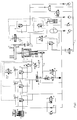
- the control of the cushion likewise includes the displacement and force control of the cushion plate 1, on which the pressure bolts 23 acting on the lower tool are supported in a known manner.
- the description is given for a stroke cycle of the press ram with an intermediate stop in the drawing area during the preliminary stroke, subsequent return stroke of the ram and subsequent continuation of the drawing process according to FIG. 1.
- the pre-acceleration represents an additional control, which, however, does not represent a need for the proposed solution.
- the stop 14 connected to the ram moves successively onto the stepped piston 25 of the piston-cylinder unit 36 shortly before the start of drawing.
- the displacement piston 22 connected to a piston rod and the cushion plate 1 with the pressure bolts 23 are pre-accelerated in the pulling direction synchronously with the respective ram speed via the locking piston 26.
- the area ratio of all stepped pistons 25 together to the effective annular surface of the locking piston 26 determines the achievable speed at the time of the upper tool striking the lower tool.
- the volume dosing by means of the tappet achieves not only the time-dependent but also the path-dependent synchronization to the tappet.
- the proportional valve 16 which is arranged in parallel with the check valve 15 in the suction line between the stepped cylinder 13 and the pressurized oil source 17 and is controlled by the press drive, enables a variable auxiliary oil flow from the stepped cylinder 25 during the pre-acceleration to the pressure oil source 17 and thus a change in the cushion pre-acceleration.
- the oil is transported from the displacement piston 22 out of the displacement cylinder 2 via the check valve 7 to the pressure oil source 17.
- the further stroke movement of the cushion is driven by a ram, whereby oil is further displaced from the displacement cylinder 2 and sucked into the pressure chamber of the locking cylinder 3.
- the oil displacement from the displacement cylinder 2 takes place in the known form via the proportional valve 8, to which the machine control system assigns a set pressure function depending on the drawing path, in accordance with the drawing tool requirements.
- a pressure transducer 27 and a check valve 6 opening in the direction of the proportional valve are additionally arranged in the line between the displacement cylinder 2 and the proportional valve 8.
- a check valve 7 opening in the direction of the pressure oil source is arranged between the displacement cylinder 2 and the pressure oil source 17. Both check valves 6 and 7 are blocked by the switching directional valve 4 and the OR valve 5 alternately or simultaneously in the direction of flow without leakage.
- the directional control valve 4 is in the switching position a, as a result of which the check valve 7 blocks the outflow to the pressure oil source 17 and the check valve 6 is depressurized and thus allows free passage to the proportional valve 8.
- the directional control valve 4 is switched from switch position a to switch position b.
- the cushion is supported on the ram with ejector force.
- Other variants are also possible.
- the leakage oil pump 19 is switched on via an input command and a pressure control circuit is activated with a slight delay.
- the directional valve 4 is switched from switch position b to switch position a.
- the setpoint pressure stored in the displacement cylinder 2 as a function of the drawing path is detected by the pressure transducer 27 and supplies the setpoint to the proportional valve 8, which is regulated according to the setpoint pressure.
- the drawing process is continued with a second input command.
- the control sequence is as follows. During the deep drawing, the oil flows out of the displacement cylinder 2 via the proportional valve 8 for counterforce control, and oil flows into the locking cylinder 3 from the pressure oil source 17. When the press ram is at a standstill, the proportional valve 8 closes in order to regulate the pressure which is assigned to the current drawing path. The pressure oil source 17 continues to act on the piston of the locking cylinder 3 and, supported by the inertial forces, the cushion is moved downwards depending on the leakage of the proportional valve 8. In order to counteract this downward movement, a signal is transmitted to the oil reservoir 20 upon activation of the tappet stop command, which activates the leakage oil pump 19.
- the press ram remains in its position, the cushion is supported on it and the current pressure is regulated depending on the drawing path (target profile).
- the press ram falls, a load change occurs on the piston rod of the cushion and the die cushion is supported against the oil column enclosed in the locking cylinder 3.
- a pressure switch 38 transmits a signal to the controller, not shown, which switches it from the pressure control to the position control.
- the setpoint for the position control should be determined and saved at the moment the ram is at a standstill.
- this position control can also be achieved according to the following description.
- a known balancing pressure is set. This balancing pressure prevents unwanted relief movements in the event of a tappet decline and is transferred to the controller as a machine parameter (sheet holder mass, mass of the cushion unit, pressure in the locking cylinder) as a setpoint for the pressure control circuit as soon as the leak oil pump 19 is activated. It is large enough to make it possible to see that the tappet has been lifted off the cushion by an increase in pressure in the locking cylinder 3. If the press ram is withdrawn, the pressure increase in the locking cylinder 3 ensures the switching of a check valve 6, 7, which is arranged between the displacement cylinder 2 and the proportional valve 8 and blocks without leakage oil. If the press ram resets, the locking cylinder 3 is relieved in connection with a renewed signal for setting the cushion condition, which existed shortly before the drawing process was interrupted.
- the sensor 21 connected to the cushion control is used.
- the proportional valve 8 is briefly controlled in a known manner to a large outlet cross section, so that the pressure in the displacement cylinder 2 is in the Oil container 20 relaxed.
- the pressure of the pressure oil source 17 acts in the locking cylinder 3, which pulls the cushion downward and prevents the pressure bolts 23 from springing open after passing through the bottom dead center through the press ram relative to the upper tool.
- the directional control valve 4 is switched from switch position a to switch position b, whereby the ejector pressure of the pressure oil source 17 on the displacement piston 22 is released and, at the same time, the oil outlet from the displacement cylinder 2 is blocked by the check valve 6.
- the check valve 9 and control valve 10 connected in series between the locking cylinder 3 and the pressure oil source 17, each of which is monitored and designed as a poppet valve, ensure leak-free sealing of the locking cylinder 3 and thus prevent an undesired upward movement of the cushion.
- a switch contact which can be variably adjusted by the press control, effects the changeover of the directional control valves 30 and 31 from switch position a to switch position b, whereby the check valve 9 and control valve 10 are opened and the ejection process is initiated.
- the control valve 10 is designed in a known manner as a blocking and throttle valve, the throttle of which can be changed by means of a pneumatically actuated actuating cylinder 32 and pressure control valve 33 and is closed by the lever 34, which is coupled to the cushion stop 24, at the upper cushion stop.
- the throttle adjustment by means of the actuating cylinder 32 enables the setting of different ejection speeds of the cushion with variable ejection forces, while the lever 34 secures the force-controlled cushion stop damping.
- the stop 14 is released from the step piston 25, as a result of which oil flows from the pressure oil source 17 via the check valve 15 into the step cylinder 13 and the step piston 25 reaches the starting position. Since the sum of the area of the stepped cylinders 25 is smaller than the annular area of the locking piston 26, the quantity of differential oil is replenished during the tappet advance from the pressure oil source 17 via the series-connected, check-controlled check valves 11 and 9.
- the pressure oil source 17 is charged by the ejector pump 18.
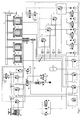
- the functional spaces for displacement (counter-holding) and ejection are arranged separately from the first exemplary embodiment.
- the ejection cylinder 38 is arranged below the locking cylinder 3.
- An advantage of this arrangement is that smaller amounts of oil with higher pressure can be used for ejection.
- the refilling of the displacement cylinder 2 during ejection takes place from the compensating cylinder 39, which is preloaded with a low pneumatic pressure and is connected in the line between the check valves 12 and 7.
- FIG. 3 shows a multi-point pull pillow according to the proposed solution.
- a displacement cylinder 2 with displacement piston 22 is arranged per cushion cushion point between cushion plate 1 and table.
- the locking cylinder 3 is centrally connected to the cushion plate 1.
- a switchable check valve 6 and a switchable check valve 7 are arranged in series, with a connection of each check valve 7 being operatively connected to the check valve 12.
- the other structure corresponds identically to the first embodiment. However, a separate arrangement of the functional spaces for displacement and counter-holding according to FIG. 2 is also possible.
Landscapes
- Engineering & Computer Science (AREA)
- Mechanical Engineering (AREA)
- Presses And Accessory Devices Thereof (AREA)
- Fluid-Pressure Circuits (AREA)
- Braking Arrangements (AREA)
Applications Claiming Priority (2)
| Application Number | Priority Date | Filing Date | Title |
|---|---|---|---|
| DE4218914 | 1992-06-10 | ||
| DE4218914A DE4218914A1 (de) | 1992-06-10 | 1992-06-10 | Hydraulische Zieheinrichtung in einer Presse |
Publications (2)
| Publication Number | Publication Date |
|---|---|
| EP0573830A1 true EP0573830A1 (fr) | 1993-12-15 |
| EP0573830B1 EP0573830B1 (fr) | 1996-10-23 |
Family
ID=6460668
Family Applications (1)
| Application Number | Title | Priority Date | Filing Date |
|---|---|---|---|
| EP93108242A Expired - Lifetime EP0573830B1 (fr) | 1992-06-10 | 1993-05-21 | Dispositif d'étirage hydraulique dans une presse |
Country Status (3)
| Country | Link |
|---|---|
| EP (1) | EP0573830B1 (fr) |
| DE (2) | DE4218914A1 (fr) |
| ES (1) | ES2093315T3 (fr) |
Cited By (2)
| Publication number | Priority date | Publication date | Assignee | Title |
|---|---|---|---|---|
| EP2335840A3 (fr) * | 2009-12-15 | 2014-12-31 | Robert Bosch GmbH | Entraînement de presse hydraulique |
| CN106762886A (zh) * | 2016-12-05 | 2017-05-31 | 重集团大连设计研究院有限公司 | 新型数控液压垫系统 |
Families Citing this family (4)
| Publication number | Priority date | Publication date | Assignee | Title |
|---|---|---|---|---|
| DE4405909A1 (de) * | 1994-02-24 | 1995-08-31 | Erfurt Umformtechnik Gmbh | Verfahren und Schaltungsanordnung zum Unterbrechen und Fortführen des Ziehprozesses an zweifachwirkenden Pressen, insbesondere hydraulischen Pressen |
| JP4956022B2 (ja) * | 2006-03-03 | 2012-06-20 | コマツ産機株式会社 | プレス機械のダイクッション制御装置 |
| DE102015016773B4 (de) | 2015-12-23 | 2024-12-24 | Wieland Petter | Verfahren zum Bearbeiten und zur Formgebung metallischer und anderer Werkstoffe |
| DE102021101060B3 (de) | 2021-01-19 | 2022-05-05 | Johannes Hülshorst | Tiefziehpresse |
Citations (4)
| Publication number | Priority date | Publication date | Assignee | Title |
|---|---|---|---|---|
| EP0173755A1 (fr) * | 1984-06-29 | 1986-03-12 | L. SCHULER GmbH | Dispositif d'étirage dans une presse |
| EP0268894A2 (fr) * | 1986-11-28 | 1988-06-01 | L. SCHULER GmbH | Dispositif d'étirage pour presse |
| DE3807683A1 (de) * | 1988-03-09 | 1989-09-21 | Schuler Gmbh L | Ziehapparat in ziehstufen von pressen |
| EP0406792A1 (fr) * | 1989-07-06 | 1991-01-09 | L. SCHULER GmbH | Couplage de réglage pour la course supérieure pour la jumelle de pression d'un dispositif d'emboutissage |
-
1992
- 1992-06-10 DE DE4218914A patent/DE4218914A1/de not_active Withdrawn
-
1993
- 1993-05-21 EP EP93108242A patent/EP0573830B1/fr not_active Expired - Lifetime
- 1993-05-21 ES ES93108242T patent/ES2093315T3/es not_active Expired - Lifetime
- 1993-05-21 DE DE59304251T patent/DE59304251D1/de not_active Expired - Fee Related
Patent Citations (4)
| Publication number | Priority date | Publication date | Assignee | Title |
|---|---|---|---|---|
| EP0173755A1 (fr) * | 1984-06-29 | 1986-03-12 | L. SCHULER GmbH | Dispositif d'étirage dans une presse |
| EP0268894A2 (fr) * | 1986-11-28 | 1988-06-01 | L. SCHULER GmbH | Dispositif d'étirage pour presse |
| DE3807683A1 (de) * | 1988-03-09 | 1989-09-21 | Schuler Gmbh L | Ziehapparat in ziehstufen von pressen |
| EP0406792A1 (fr) * | 1989-07-06 | 1991-01-09 | L. SCHULER GmbH | Couplage de réglage pour la course supérieure pour la jumelle de pression d'un dispositif d'emboutissage |
Cited By (2)
| Publication number | Priority date | Publication date | Assignee | Title |
|---|---|---|---|---|
| EP2335840A3 (fr) * | 2009-12-15 | 2014-12-31 | Robert Bosch GmbH | Entraînement de presse hydraulique |
| CN106762886A (zh) * | 2016-12-05 | 2017-05-31 | 重集团大连设计研究院有限公司 | 新型数控液压垫系统 |
Also Published As
| Publication number | Publication date |
|---|---|
| ES2093315T3 (es) | 1996-12-16 |
| EP0573830B1 (fr) | 1996-10-23 |
| DE4218914A1 (de) | 1993-12-16 |
| DE59304251D1 (de) | 1996-11-28 |
Similar Documents
| Publication | Publication Date | Title |
|---|---|---|
| DE3640236C2 (fr) | ||
| EP2384834B1 (fr) | Coussin de serre-flan hydraulique avec un vérin hydraulique | |
| CH662532A5 (de) | Hydraulikeinrichtung fuer die formschliesseinheit einer kunststoff-spritzgiessmaschine. | |
| EP0173755B1 (fr) | Dispositif d'étirage dans une presse | |
| EP2183096A1 (fr) | Système d'entraînement pour presses hydrauliques | |
| EP0192115B1 (fr) | Appareil d'étirage pour presses | |
| EP0573830B1 (fr) | Dispositif d'étirage hydraulique dans une presse | |
| DE3343172C2 (fr) | ||
| DE10336279A1 (de) | Einrichtung zur Steuerung des Ziehvorgangs bei einer Transferpresse | |
| DE4100716A1 (de) | Einrichtung zum blechhalten in einfachwirkenden pressen | |
| DE4128610C2 (de) | Pressenanordnung mit Dämpfungseinrichtung und Hilfsvorrichtung | |
| WO2010051913A1 (fr) | Convertisseur de forces hydraulique | |
| EP1252010A1 (fr) | Presse | |
| DE4302263A1 (de) | Mechanische Stufenpresse mit hydraulischen Arbeitshubeinheiten | |
| DE2743772C2 (de) | Gegenschlaghämmermaschine | |
| DE19711780A1 (de) | Zieheinrichtung für Ziehpressen | |
| DE3619109C2 (de) | Einrichtung zur Auftreffstoßdämpfung für Ziehkissen an Pressen | |
| DE102004035590A1 (de) | Presse mit verriegeltem Stößel | |
| DE2432774B2 (de) | Presse, insbesondere Feinschneidpresse | |
| EP0773076B1 (fr) | Dispositif de commande de la pression dans des serre-flans hydrauliques des presses à emboutir | |
| DE102023113473B4 (de) | Hydraulische Umformmaschine zur Werkstückumformung, Hydrauliksteuereinheit und Verfahren zur Steuerung eines Hydraulikzylinders einer hydraulischen Umformmaschine | |
| DE19639220A1 (de) | Einrichtung zur Vorbeschleunigung vom Blechhalter einfachwirkender Pressen | |
| EP0406792A1 (fr) | Couplage de réglage pour la course supérieure pour la jumelle de pression d'un dispositif d'emboutissage | |
| EP0716916B1 (fr) | Procédé d'ajustement de l'impact des outils supérieurs et inférieurs d'une presse, diminuant le bruit, et entraínement du coulisseau avec un dispositif d'application du procédé | |
| CH667500A5 (de) | Vorrichtung zum ansteuern der presszylinder an den lagerstellen einer presswalze. |
Legal Events
| Date | Code | Title | Description |
|---|---|---|---|
| PUAI | Public reference made under article 153(3) epc to a published international application that has entered the european phase |
Free format text: ORIGINAL CODE: 0009012 |
|
| AK | Designated contracting states |
Kind code of ref document: A1 Designated state(s): DE ES FR GB IT SE |
|
| 17P | Request for examination filed |
Effective date: 19940217 |
|
| GRAG | Despatch of communication of intention to grant |
Free format text: ORIGINAL CODE: EPIDOS AGRA |
|
| GRAH | Despatch of communication of intention to grant a patent |
Free format text: ORIGINAL CODE: EPIDOS IGRA |
|
| 17Q | First examination report despatched |
Effective date: 19960226 |
|
| GRAH | Despatch of communication of intention to grant a patent |
Free format text: ORIGINAL CODE: EPIDOS IGRA |
|
| GRAA | (expected) grant |
Free format text: ORIGINAL CODE: 0009210 |
|
| AK | Designated contracting states |
Kind code of ref document: B1 Designated state(s): DE ES FR GB IT SE |
|
| GBT | Gb: translation of ep patent filed (gb section 77(6)(a)/1977) |
Effective date: 19961023 |
|
| REF | Corresponds to: |
Ref document number: 59304251 Country of ref document: DE Date of ref document: 19961128 |
|
| REG | Reference to a national code |
Ref country code: ES Ref legal event code: FG2A Ref document number: 2093315 Country of ref document: ES Kind code of ref document: T3 |
|
| ITF | It: translation for a ep patent filed | ||
| ET | Fr: translation filed | ||
| PLBE | No opposition filed within time limit |
Free format text: ORIGINAL CODE: 0009261 |
|
| 26N | No opposition filed | ||
| REG | Reference to a national code |
Ref country code: GB Ref legal event code: IF02 |
|
| PGFP | Annual fee paid to national office [announced via postgrant information from national office to epo] |
Ref country code: DE Payment date: 20050427 Year of fee payment: 13 |
|
| PGFP | Annual fee paid to national office [announced via postgrant information from national office to epo] |
Ref country code: GB Payment date: 20050512 Year of fee payment: 13 |
|
| PGFP | Annual fee paid to national office [announced via postgrant information from national office to epo] |
Ref country code: FR Payment date: 20050519 Year of fee payment: 13 |
|
| PGFP | Annual fee paid to national office [announced via postgrant information from national office to epo] |
Ref country code: SE Payment date: 20050524 Year of fee payment: 13 |
|
| PGFP | Annual fee paid to national office [announced via postgrant information from national office to epo] |
Ref country code: ES Payment date: 20050531 Year of fee payment: 13 |
|
| PG25 | Lapsed in a contracting state [announced via postgrant information from national office to epo] |
Ref country code: GB Free format text: LAPSE BECAUSE OF NON-PAYMENT OF DUE FEES Effective date: 20060521 |
|
| PG25 | Lapsed in a contracting state [announced via postgrant information from national office to epo] |
Ref country code: SE Free format text: LAPSE BECAUSE OF NON-PAYMENT OF DUE FEES Effective date: 20060522 Ref country code: ES Free format text: LAPSE BECAUSE OF NON-PAYMENT OF DUE FEES Effective date: 20060522 |
|
| PGFP | Annual fee paid to national office [announced via postgrant information from national office to epo] |
Ref country code: IT Payment date: 20060531 Year of fee payment: 14 |
|
| PG25 | Lapsed in a contracting state [announced via postgrant information from national office to epo] |
Ref country code: DE Free format text: LAPSE BECAUSE OF NON-PAYMENT OF DUE FEES Effective date: 20061201 |
|
| EUG | Se: european patent has lapsed | ||
| GBPC | Gb: european patent ceased through non-payment of renewal fee |
Effective date: 20060521 |
|
| REG | Reference to a national code |
Ref country code: FR Ref legal event code: ST Effective date: 20070131 |
|
| REG | Reference to a national code |
Ref country code: ES Ref legal event code: FD2A Effective date: 20060522 |
|
| PG25 | Lapsed in a contracting state [announced via postgrant information from national office to epo] |
Ref country code: FR Free format text: LAPSE BECAUSE OF NON-PAYMENT OF DUE FEES Effective date: 20060531 |
|
| PG25 | Lapsed in a contracting state [announced via postgrant information from national office to epo] |
Ref country code: IT Free format text: LAPSE BECAUSE OF NON-PAYMENT OF DUE FEES Effective date: 20070521 |