EP0574004A2 - Vor dem Objektiv angeordnetes Abtastsystem mit flexiblem optischem Träger - Google Patents
Vor dem Objektiv angeordnetes Abtastsystem mit flexiblem optischem Träger Download PDFInfo
- Publication number
- EP0574004A2 EP0574004A2 EP93109378A EP93109378A EP0574004A2 EP 0574004 A2 EP0574004 A2 EP 0574004A2 EP 93109378 A EP93109378 A EP 93109378A EP 93109378 A EP93109378 A EP 93109378A EP 0574004 A2 EP0574004 A2 EP 0574004A2
- Authority
- EP
- European Patent Office
- Prior art keywords
- light
- objective lens
- light emitter
- emitter
- scanning
- Prior art date
- Legal status (The legal status is an assumption and is not a legal conclusion. Google has not performed a legal analysis and makes no representation as to the accuracy of the status listed.)
- Granted
Links
Images







Classifications
-
- G—PHYSICS
- G06—COMPUTING OR CALCULATING; COUNTING
- G06K—GRAPHICAL DATA READING; PRESENTATION OF DATA; RECORD CARRIERS; HANDLING RECORD CARRIERS
- G06K7/00—Methods or arrangements for sensing record carriers, e.g. for reading patterns
- G06K7/10—Methods or arrangements for sensing record carriers, e.g. for reading patterns by electromagnetic radiation, e.g. optical sensing; by corpuscular radiation
- G06K7/10544—Methods or arrangements for sensing record carriers, e.g. for reading patterns by electromagnetic radiation, e.g. optical sensing; by corpuscular radiation by scanning of the records by radiation in the optical part of the electromagnetic spectrum
- G06K7/10821—Methods or arrangements for sensing record carriers, e.g. for reading patterns by electromagnetic radiation, e.g. optical sensing; by corpuscular radiation by scanning of the records by radiation in the optical part of the electromagnetic spectrum further details of bar or optical code scanning devices
- G06K7/10881—Methods or arrangements for sensing record carriers, e.g. for reading patterns by electromagnetic radiation, e.g. optical sensing; by corpuscular radiation by scanning of the records by radiation in the optical part of the electromagnetic spectrum further details of bar or optical code scanning devices constructional details of hand-held scanners
-
- G—PHYSICS
- G06—COMPUTING OR CALCULATING; COUNTING
- G06K—GRAPHICAL DATA READING; PRESENTATION OF DATA; RECORD CARRIERS; HANDLING RECORD CARRIERS
- G06K7/00—Methods or arrangements for sensing record carriers, e.g. for reading patterns
- G06K7/10—Methods or arrangements for sensing record carriers, e.g. for reading patterns by electromagnetic radiation, e.g. optical sensing; by corpuscular radiation
-
- G—PHYSICS
- G06—COMPUTING OR CALCULATING; COUNTING
- G06F—ELECTRIC DIGITAL DATA PROCESSING
- G06F1/00—Details not covered by groups G06F3/00 - G06F13/00 and G06F21/00
- G06F1/16—Constructional details or arrangements
- G06F1/1613—Constructional details or arrangements for portable computers
- G06F1/163—Wearable computers, e.g. on a belt
-
- G—PHYSICS
- G06—COMPUTING OR CALCULATING; COUNTING
- G06F—ELECTRIC DIGITAL DATA PROCESSING
- G06F3/00—Input arrangements for transferring data to be processed into a form capable of being handled by the computer; Output arrangements for transferring data from processing unit to output unit, e.g. interface arrangements
- G06F3/01—Input arrangements or combined input and output arrangements for interaction between user and computer
- G06F3/03—Arrangements for converting the position or the displacement of a member into a coded form
- G06F3/033—Pointing devices displaced or positioned by the user, e.g. mice, trackballs, pens or joysticks; Accessories therefor
- G06F3/0346—Pointing devices displaced or positioned by the user, e.g. mice, trackballs, pens or joysticks; Accessories therefor with detection of the device orientation or free movement in a three-dimensional [3D] space, e.g. 3D mice, 6-DOF [six degrees of freedom] pointers using gyroscopes, accelerometers or tilt-sensors
-
- G—PHYSICS
- G06—COMPUTING OR CALCULATING; COUNTING
- G06K—GRAPHICAL DATA READING; PRESENTATION OF DATA; RECORD CARRIERS; HANDLING RECORD CARRIERS
- G06K7/00—Methods or arrangements for sensing record carriers, e.g. for reading patterns
- G06K7/10—Methods or arrangements for sensing record carriers, e.g. for reading patterns by electromagnetic radiation, e.g. optical sensing; by corpuscular radiation
- G06K7/10544—Methods or arrangements for sensing record carriers, e.g. for reading patterns by electromagnetic radiation, e.g. optical sensing; by corpuscular radiation by scanning of the records by radiation in the optical part of the electromagnetic spectrum
- G06K7/10554—Moving beam scanning
- G06K7/10564—Light sources
-
- G—PHYSICS
- G06—COMPUTING OR CALCULATING; COUNTING
- G06K—GRAPHICAL DATA READING; PRESENTATION OF DATA; RECORD CARRIERS; HANDLING RECORD CARRIERS
- G06K7/00—Methods or arrangements for sensing record carriers, e.g. for reading patterns
- G06K7/10—Methods or arrangements for sensing record carriers, e.g. for reading patterns by electromagnetic radiation, e.g. optical sensing; by corpuscular radiation
- G06K7/10544—Methods or arrangements for sensing record carriers, e.g. for reading patterns by electromagnetic radiation, e.g. optical sensing; by corpuscular radiation by scanning of the records by radiation in the optical part of the electromagnetic spectrum
- G06K7/10554—Moving beam scanning
- G06K7/10564—Light sources
- G06K7/10584—Source control
-
- G—PHYSICS
- G06—COMPUTING OR CALCULATING; COUNTING
- G06K—GRAPHICAL DATA READING; PRESENTATION OF DATA; RECORD CARRIERS; HANDLING RECORD CARRIERS
- G06K7/00—Methods or arrangements for sensing record carriers, e.g. for reading patterns
- G06K7/10—Methods or arrangements for sensing record carriers, e.g. for reading patterns by electromagnetic radiation, e.g. optical sensing; by corpuscular radiation
- G06K7/10544—Methods or arrangements for sensing record carriers, e.g. for reading patterns by electromagnetic radiation, e.g. optical sensing; by corpuscular radiation by scanning of the records by radiation in the optical part of the electromagnetic spectrum
- G06K7/10554—Moving beam scanning
- G06K7/10594—Beam path
- G06K7/10603—Basic scanning using moving elements
- G06K7/10633—Basic scanning using moving elements by oscillation
-
- G—PHYSICS
- G06—COMPUTING OR CALCULATING; COUNTING
- G06K—GRAPHICAL DATA READING; PRESENTATION OF DATA; RECORD CARRIERS; HANDLING RECORD CARRIERS
- G06K7/00—Methods or arrangements for sensing record carriers, e.g. for reading patterns
- G06K7/10—Methods or arrangements for sensing record carriers, e.g. for reading patterns by electromagnetic radiation, e.g. optical sensing; by corpuscular radiation
- G06K7/10544—Methods or arrangements for sensing record carriers, e.g. for reading patterns by electromagnetic radiation, e.g. optical sensing; by corpuscular radiation by scanning of the records by radiation in the optical part of the electromagnetic spectrum
- G06K7/10554—Moving beam scanning
- G06K7/10594—Beam path
- G06K7/10603—Basic scanning using moving elements
- G06K7/10633—Basic scanning using moving elements by oscillation
- G06K7/10643—Activating means
- G06K7/10653—Activating means using flexible or piezoelectric means
-
- G—PHYSICS
- G06—COMPUTING OR CALCULATING; COUNTING
- G06K—GRAPHICAL DATA READING; PRESENTATION OF DATA; RECORD CARRIERS; HANDLING RECORD CARRIERS
- G06K7/00—Methods or arrangements for sensing record carriers, e.g. for reading patterns
- G06K7/10—Methods or arrangements for sensing record carriers, e.g. for reading patterns by electromagnetic radiation, e.g. optical sensing; by corpuscular radiation
- G06K7/10544—Methods or arrangements for sensing record carriers, e.g. for reading patterns by electromagnetic radiation, e.g. optical sensing; by corpuscular radiation by scanning of the records by radiation in the optical part of the electromagnetic spectrum
- G06K7/10821—Methods or arrangements for sensing record carriers, e.g. for reading patterns by electromagnetic radiation, e.g. optical sensing; by corpuscular radiation by scanning of the records by radiation in the optical part of the electromagnetic spectrum further details of bar or optical code scanning devices
- G06K7/10861—Methods or arrangements for sensing record carriers, e.g. for reading patterns by electromagnetic radiation, e.g. optical sensing; by corpuscular radiation by scanning of the records by radiation in the optical part of the electromagnetic spectrum further details of bar or optical code scanning devices sensing of data fields affixed to objects or articles, e.g. coded labels
- G06K7/10871—Methods or arrangements for sensing record carriers, e.g. for reading patterns by electromagnetic radiation, e.g. optical sensing; by corpuscular radiation by scanning of the records by radiation in the optical part of the electromagnetic spectrum further details of bar or optical code scanning devices sensing of data fields affixed to objects or articles, e.g. coded labels randomly oriented data-fields, code-marks therefore, e.g. concentric circles-code
-
- G—PHYSICS
- G06—COMPUTING OR CALCULATING; COUNTING
- G06K—GRAPHICAL DATA READING; PRESENTATION OF DATA; RECORD CARRIERS; HANDLING RECORD CARRIERS
- G06K7/00—Methods or arrangements for sensing record carriers, e.g. for reading patterns
- G06K7/10—Methods or arrangements for sensing record carriers, e.g. for reading patterns by electromagnetic radiation, e.g. optical sensing; by corpuscular radiation
- G06K7/10544—Methods or arrangements for sensing record carriers, e.g. for reading patterns by electromagnetic radiation, e.g. optical sensing; by corpuscular radiation by scanning of the records by radiation in the optical part of the electromagnetic spectrum
- G06K7/10821—Methods or arrangements for sensing record carriers, e.g. for reading patterns by electromagnetic radiation, e.g. optical sensing; by corpuscular radiation by scanning of the records by radiation in the optical part of the electromagnetic spectrum further details of bar or optical code scanning devices
- G06K7/10881—Methods or arrangements for sensing record carriers, e.g. for reading patterns by electromagnetic radiation, e.g. optical sensing; by corpuscular radiation by scanning of the records by radiation in the optical part of the electromagnetic spectrum further details of bar or optical code scanning devices constructional details of hand-held scanners
- G06K7/10891—Methods or arrangements for sensing record carriers, e.g. for reading patterns by electromagnetic radiation, e.g. optical sensing; by corpuscular radiation by scanning of the records by radiation in the optical part of the electromagnetic spectrum further details of bar or optical code scanning devices constructional details of hand-held scanners the scanner to be worn on a finger or on a wrist
-
- G—PHYSICS
- G06—COMPUTING OR CALCULATING; COUNTING
- G06Q—INFORMATION AND COMMUNICATION TECHNOLOGY [ICT] SPECIALLY ADAPTED FOR ADMINISTRATIVE, COMMERCIAL, FINANCIAL, MANAGERIAL OR SUPERVISORY PURPOSES; SYSTEMS OR METHODS SPECIALLY ADAPTED FOR ADMINISTRATIVE, COMMERCIAL, FINANCIAL, MANAGERIAL OR SUPERVISORY PURPOSES, NOT OTHERWISE PROVIDED FOR
- G06Q20/00—Payment architectures, schemes or protocols
- G06Q20/30—Payment architectures, schemes or protocols characterised by the use of specific devices or networks
- G06Q20/34—Payment architectures, schemes or protocols characterised by the use of specific devices or networks using cards, e.g. integrated circuit [IC] cards or magnetic cards
- G06Q20/343—Cards including a counter
-
- G—PHYSICS
- G07—CHECKING-DEVICES
- G07F—COIN-FREED OR LIKE APPARATUS
- G07F7/00—Mechanisms actuated by objects other than coins to free or to actuate vending, hiring, coin or paper currency dispensing or refunding apparatus
- G07F7/02—Mechanisms actuated by objects other than coins to free or to actuate vending, hiring, coin or paper currency dispensing or refunding apparatus by keys or other credit registering devices
-
- G—PHYSICS
- G07—CHECKING-DEVICES
- G07G—REGISTERING THE RECEIPT OF CASH, VALUABLES, OR TOKENS
- G07G1/00—Cash registers
- G07G1/0036—Checkout procedures
- G07G1/0045—Checkout procedures with a code reader for reading of an identifying code of the article to be registered, e.g. barcode reader or radio-frequency identity [RFID] reader
-
- G—PHYSICS
- G06—COMPUTING OR CALCULATING; COUNTING
- G06F—ELECTRIC DIGITAL DATA PROCESSING
- G06F2203/00—Indexing scheme relating to G06F3/00 - G06F3/048
- G06F2203/033—Indexing scheme relating to G06F3/033
- G06F2203/0331—Finger worn pointing device
-
- G—PHYSICS
- G06—COMPUTING OR CALCULATING; COUNTING
- G06K—GRAPHICAL DATA READING; PRESENTATION OF DATA; RECORD CARRIERS; HANDLING RECORD CARRIERS
- G06K7/00—Methods or arrangements for sensing record carriers, e.g. for reading patterns
- G06K7/10—Methods or arrangements for sensing record carriers, e.g. for reading patterns by electromagnetic radiation, e.g. optical sensing; by corpuscular radiation
- G06K2007/10524—Hand-held scanners
- G06K2007/10534—Scanner to be worn on a finger or on a wrist
-
- G—PHYSICS
- G06—COMPUTING OR CALCULATING; COUNTING
- G06K—GRAPHICAL DATA READING; PRESENTATION OF DATA; RECORD CARRIERS; HANDLING RECORD CARRIERS
- G06K2207/00—Other aspects
- G06K2207/1016—Motor control or optical moving unit control
Definitions
- the present invention relates to optical scanners for optically reading information, such as bar codes.
- this invention relates to small light weight scanner structures which do not require a moving mirror to scan a light beam across the information.
- Optical readers such as bar code readers, are now quite common.
- a bar code comprises a series of encoded symbols, and each symbol consists of a series of light and dark regions, typically in the form of rectangles. The widths of the dark regions, the bars, and/or the widths of the light spaces between the bars indicate the encoded information.
- a bar code reader illuminates the code and senses light reflected from the code to detect the widths and spacings of the code symbols and derive the encoded data.
- Bar code reading type data input systems improve the efficiency and accuracy of data input for a wide variety of applications.
- the ease of data input in such systems facilitates more frequent and detailed data input, for example to provide efficient inventories, tracking of work in progress, etc.
- users or employees must be willing to consistently use the bar code readers. The readers therefore must be easy and convenient to operate.
- a variety of scanning devices are known.
- One particularly advantageous type of reader is an optical scanner which scans a beam of light, such as a laser beam, across the symbols.
- a light source such as a laser generates a light beam which is optically modified to form a beam spot of a certain size at the working distance and is directed by optical components along a light path toward a bar code symbol located in the vicinity of the working distance for reflection from the symbol.
- a photodetector having a field of view extending across and slightly past the symbol detects light of variable intensity reflected off the symbol and generates electrical signals indicative of the detected light.
- a scanning component is situated in the light path. The scanning component may either sweep the beam spot across the symbol and trace a scan line across and past the symbol, or scan the field of view of the photodetector, or do both.
- a digitizer associated with or included in the scanner, processes the analog signal to produce a pulse signal where the widths and spacings between the pulses correspond to the widths of the bars and the spacings between the bars.
- the digitizer serves as an edge detector or wave shaper circuit, and the threshold value set by the digitizer determines what points of the analog signal represent bar edges.
- the pulse signal from the digitizer is applied to a decoder.
- the decoder first determines the pulse widths and spacings of the signal from the digitizer.
- the decoder analyzes the widths and spacings to find and decode a legitimate bar code message. This includes analysis to recognize legitimate characters and sequences, as defined by the appropriate code standard. This may also include an initial recognition of the particular standard the scanned symbol conforms to. This recognition of the standard is typically referred to as autodiscrimination.
- the optical scanner be constructed in the form of a handheld unit, typically in the form of a pistol.
- the user points the scanner at the object and operates a trigger to activate the scanning of the bar code.
- a light source such as a visible laser diode (hereinafter VLD) emits a beam of light.
- VLD visible laser diode
- U.S. Patent No. 4,251,798 discloses a rotating polygon having a planar mirror at each side, each mirror tracing a scan line across the symbol.
- Patent Nos. 4,387,297 and 4,409,470 both employ a planar mirror which is repetitively and reciprocally driven in alternate circumferential directions about a drive shaft on which the mirror is mounted.
- U.S. Patent No. 4,816,660 discloses a multi-mirror construction composed of a generally concave mirror portion and a generally planar mirror portion. The multi-mirror construction is repetitively reciprocally driven in alternate circumferential directions about a drive shaft on which the multi-mirror construction is mounted.
- the mirror and means to oscillate the mirror add size and weight to the handheld scanner.
- a large heavy handheld unit can produce fatigue.
- the user is reluctant to operate the scanner, which defeats the data gathering purposes for which bar code systems are intended.
- Another problem with scanners of the type discussed above relates to the scan field and the size of the spot at the point where the beam impacts on the information.
- Lasers emit a narrow core of radiation referred to as the laser beam.
- the beam cross-section varies as the laser beam propagates, particularly after focusing thereof by a lens.
- the minimum beam diameter is called the "beam waist.”
- the scanning element e.g. the moveable mirror, typically is positioned after the objective lens so as to scan the focused beam. Such scanning is referred to as "post objective" scanning.
- the objective lens in such scanners only needs to be slightly larger than the beam, and the scanning mirror can be somewhat smaller than the beam diameter.
- the mirror rotation produces a curved or arcuate scan of the focal point of the beam.
- This curved scan field means that the focal point of the beam actually moves into and out of the plane of the information being scanned, and the part of the beam which impacts the plane of the information changes. Consequently, the spot size changes substantially from point to point along the scan line on the information surface.
- Such variations in spot size cause the intensity of light reflection sensed by the photodetector to vary, which may interfere with accurate sensing of reflection variations due to variations in the scanned information.
- a non-laser light emitting diode, an optical assembly, a photodetector, and electronic preamplifier/filter circuitry are all fixedly mounted on a common support that is connected to a cantilevered bimorph which is reciprocally driven to jointly move all the aforementioned components back and forth over a bar code symbol to be scanned.
- the large volume and heavy mass of all the commonly mounted non-laser system components require the expenditure of a great deal of power for the driver. This is not altogether practical in those cases, e.g. battery- powered operation, where power consumption is to be held to a minimum. Also, moving only one or more non-mirrored system components relative to another for conserving power was heretofore not considered desirable, because of optical alignment problems.
- the components for the light scanning system can be mounted together in a common assembly to constitute a compact, lightweight, scan module.
- a scan module is mounted in an interchangeable, modular manner in housings of different configurations.
- the housing can be hand- held and shaped as a cylinder in a so-called flashlight-type configuration, or shaped as a box, or shaped with a gun-like configuration.
- the housing can be mounted on the back of an operator's arm (see, for example, U.S. Patent No. 4,766,299) or on one or more fingers of the operator's hand, typically with the aid of a strap, a clip, or a glove.
- the housing can be mounted on a countertop workstation.
- the housing can be mounted in a mobile cart, or shopping cart, or, in some cases, even in a stationary installation.
- the mass of the moving components should be as low as possible to minimize the power required to produce the scanning movement and to facilitate operation at high scanning speeds.
- the objective of this invention is to provide a scanner which is smaller and lighter weight, particularly when held by an operator, and which is easier to manipulate to scan encoded data.
- a further objective is to produce a durable robust scanning system at a relatively low cost.
- Another objective of the invention is to reduce the mass of the components which actually move to scan the beam. This mass reduction reduces the power required to produce the movement and facilitates operation of the scanner at high scanning frequencies.
- a further objective of the invention is to design the optics and scanning system to automatically compensate for variations in the beam spot size at the point the beam impacts on the surface of the optically encoded information due to the curved field produced by the motion of the scanning element.
- the invention is a mirrorless optical scanner including a light emitter and an objective lens for focusing light from the emitter on a surface of information to be scanned.
- a flexible member movably supports the objective lens in front of the light emitter. The flexible member permits lateral movement of the objective lens with respect to light from the light emitter.
- the scanner also includes means for laterally reciprocating the objective lens during emission of light by the light emitter to cause the light to scan the surface.
- the objective scanning using the flexible member to support the objective lens provides a small light weight scanner. Also, the mass of the moving components is small to facilitate low power operation and operation at high scanning speeds.
- the objective lens can be a condenser lens of glass or plastic; however, to further reduce size and mass, the invention uses a fresnel lens.
- the flexible member for supporting the lens.
- the lens could be supported by a pair of convoluted diaphragm springs or a so-called spider spring.
- the flexible member comprises a pair of flexible strips made from mylar film. The lens is supported between edges of the flat mylar strips at a moveable end of the strips. The opposite ends of the strips are secured to a relatively fixed structure, e.g., a point on a chassis.
- the mylar film strip construction of the flexible means for mounting the lens provides a relatively inexpensive and durable type of flexible structure.
- the invention also includes a number of arrangements for providing the necessary aperture stop.
- part of the lens support structure forms the aperture.
- the aperture reciprocates with the lens.
- Alternate embodiments include a fixed position aperture.
- the fixed aperture plate can be mounted in front of the lens, or the fixed aperture plate can be mounted between the front of the laser diode and the rear surface of the objective lens.
- the means for laterally reciprocating the lens can take a number of different forms but preferably comprise a permanent magnet and a coil held in a fixed position in proximity to the permanent magnet.
- an alternating current signal is applied to the electromagnet it produces a magnetic field which acts on the permanent magnet to oscillate the permanent magnet and the attached lens.
- This magnetic drive system can be quite small and light weight, yet it operates at high frequencies in response to low power drive signals.
- the present invention consists of an improvement in an optical scanning system for emitting light and scanning the light across a surface.
- the improvement comprises at least one flexible strip for mounting an optical component of the scanning system to allow reciprocal movement.
- This aspect of the invention also includes means to laterally move the optical component so that the light scans across the surface.
- the optical component mounted for reciprocal movement can be either an objective lens or the light emitter.
- a further embodiment of the invention provides two dimensional scanning.
- the basic one dimensional scanner is itself mounted as a moveable assembly on a second flexible support structure, for example an additional flexible mylar film strip.
- a second permanent magnet is attached to the moveable assembly and a second electromagnet responds to a second alternating current signal to reciprocally move the assembly in a second direction.
- the invention comprises a coil and bobbin with a flexible member concentrically mounted within the bobbin.
- This flexible member supports the laser diode.
- a permanent magnet is attached to the laser diode.
- the permanent magnet can take the form of a circular magnet surrounding a visible laser diode type emitter.
- An alternating current applied to the coil produces a torque on the permanent magnetic.
- the flexibly mounted light emitter oscillates in its flexible mounting structure.
- the invention uses a number of configurations for mounting the light emitter and the flexible mounting means.
- a number of configurations for mounting the light emitter and the flexible mounting means For example, in an embodiment using a laser diode emitter, and mylar strips to flexibly mount an objective lens, two plates are bolted together to clamp the diode and the fixed ends of the mylar strip.
- the invention is a method of objective scanning of optically encoded information with automatic compensation to minimize variations in spot size of a beam of light as it scans across encoded information.
- This method starts with production of a laser beam and focusing the beam to a waist through an objective lens.
- the objective lens is reciprocated laterally with respect to the beam so that the waist of the focused beam scans through an arcuate scan field.
- the optically encoded information is located at a distance from the objective lens. This distance is such that, during scanning through the arcuate scan field, the waist of the focused beam of light passes through the plane of the optically encoded information at the ends of the optically encoded information.
- the waist of the focused beam would be behind the optically encoded information at the center of the arcuate scan field.
- the laser beam is focused to a waist by passing the beam through the objective lens and focusing the beam to a focal point located at a distance from the objective lens.
- the objective lens moves back and forth through an arc across the path of the beam of light.
- the optically encoded information is located so that, when the lens is deflected to direct the beam at either end of the optically encoded information, the beam waist intersects the plane of the optically encoded information at the ends of the optically encoded information.
- the length of the beam of light between the lens and the surface of the information equals the image distance of the optical system.
- the invention provides a flat wire flexible cable to connect to a movably mounted light emitter.
- the light emitter can be one mounted for reciprocal movement in the manner discussed above.
- the moveable light emitter could be a laser diode or the like mounted on the output shaft of a motor.
- the inventive scanning modules are incorporated into a scanning unit.
- the scanning unit includes one of the above discussed modules, to produce a moving beam for optically scanning a surface on which encoded indicia of varying reflectivity are formed.
- the scanning unit also includes a photodetector for sensing light reflected from the scanned surface and producing a proportional electrical signal.
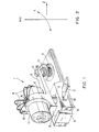
- Figure 1 depicts a mirrorless scanning unit 1 of the present invention.
- a light emitter such as a visible laser diode or VLD 11, emits a beam of light to generate a scan line.
- the VLD 11 may be mounted on the pivotable shaft of a motor or on any material means capable of producing oscillating motion.
- the VLD 11 is attached to the top end of a rotatable or pivotable shaft 13.
- the shaft 13 is pivotably mounted in a scanner base 50.
- the shaft can be installed either on any known type of bearing or just to rotate in the plastic body of base 50.
- the VLD 11 and shaft 13 together form a moving assembly 10 for scanning the beam of light from the VLD type light emitter.
- the moving assembly 10 also includes a collar 12 and a lever arm 14 attached to the shaft 13. A force applied to the end of lever arm 14 produces the oscillatory movement of assembly 10, as will be discussed later.
- the collar 12 secures the VLD 11 to the moving assembly 10.
- the VLD 11 is secured at a point atop of the shaft 13, such that the VLD 11 is effectively located on the pivot axis of the shaft 13 and aligned to emit light in a direction perpendicular to the axis of the shaft.
- Other arrangements of the VLD and shaft are possible.
- the VLD could be located at a position offset from the axis.
- the collar could support the VLD at an angle with respect to the shaft.
- Figure 2 illustrates the relationship of the motion and light emission of the VLD 11 to the axis of the shaft 13.
- the short rotational arc o about the shaft axis represents the back and forth pivotal oscillation of the VLD 11.
- the VLD 11 emits light in direction I toward a targeted object, such as a bar code (not shown).
- a targeted object such as a bar code (not shown).
- the emitted light I will scan back and forth across the targeted image.
- the targeted image will be an indicia having varying reflective characteristics which represent information.
- the image code comprises a series of bars, with spaces therebetween, which together form a bar code symbol.
- three thin wires 15 connect the leads of the VLD 11 on one side to a stationary holder 17 on the other.
- one flexible cable could be used.
- the wires 15 or cable are attached to an intermediate fixing point 16 atop the collar 12.
- the point 16 is located on the axis of the oscillation of moving assembly 10 and shaft 13 to minimize tension on the lead wires due to the zero linear speed at that point.
- the wires could be slack and hang loose or be coiled, so long as the wires provide a flexible connection to the oscillating VLD.
- the wires comprise a flexible flat wire cable.
- IMM induced magnetization motor
- the IMM type motor has been disclosed in commonly assigned application Serial Number 07/520,464, filed on May 8, 1990, entitled SCANNING ARRANGEMENT, which is herein incorporated entirely by reference. In that prior application the IMM oscillated a scanning mirror.
- a restoring force is provided by the combination of a fixed position core and coil with a moveable permanent magnet.
- the flat wire also provides a restoring force. If the permanent magnet is mounted on the end of a lever arm attached to a rotatable shaft, the force takes the form of a torque about the axis of the shaft.
- a core 21 comprises a bobbin around which the coil 23 is wound such that the core and coil are entirely concentric to minimize size and weight.
- the permanent magnet 25 is rigidly mounted at the end of the lever arm 14 of the moving assembly 10. Location of the permanent magnet 25 at a distance from the axis of the shaft 13 causes the magnetic force applied to the lever arm 14 through the permanent magnet 25 to produce a torque about the axis of the shaft 13.
- the core 21 is made of a soft steel to prevent residual magnetization and is magnetically neutral in this case.
- axially magnetized permanent magnet 25 which is attached to the moving assembly through the lever arm, positions itself above the central axis of the core 21 by the attraction of the magnet 25 to the steel of the core 21.
- the moving assembly returns to its rest position at the center of its rotational arc, i.e. facing straight forward.
- the current applied to the coil takes the form of a cyclical AC signal, such as a sign wave, a pulse signal, a triangular wave, etc.
- the induced magnetic forces will produce an oscillatory movement of the permanent magnet 25 and the attached moving assembly 10.
- the IMM is preferred for the embodiment of Figure 1, other arrangements could produce the necessary oscillatory motion.
- the VLD 11 could be installed on the rotating shaft of a motor (see, e.g., Figure 26).
- other arrangements for mounting the VLD and connecting the moving assembly to the IMM are within the scope of the present invention.
- the permanent magnet and VLD could both be mounted on a moveable or flexible bridge support directly over the bobbin coil so that the permanent magnet and VLD oscillate laterally together in response to the cyclical AC signal applied to the bobbin coil.
- the scanner When used as a scanner for reading optically encoded information, such as a bar code, the scanner also includes a light detector, such as photodiode 31.
- a light detector such as photodiode 31.
- the front of the scanner base 50 supports photodiode 31 in a position and orientation whereby light from the VLD 11 reflected by a scanned image impinges on the light sensitive area of photodiode 31.
- the photodiode 31 receives an amount of light reflected back from the target, e.g. a bar code label, and converts that reflected light into an electrical current.
- a filter, pre-amplification and amplification stages may be provided on a printed circuit board 60 shown attached to the bottom of the scanner base 50. The pre-amplification and amplification stages convert a current from photodiode 31 into an electrical signal to be sent to digitizer and the rest of a processing circuitry contained in a separate unit.
- a trigger button 33 is mounted on one side of the unit. A user operates button 33 to activate the unit.
- the mirrorless scanning unit was only 1 " long, by 1.25" high, by 0.625" wide.
- the exterior dimensions of a housing containing the mirrorless scanner are 1.1 " long, by 1.4" high, by 0.7" wide. It takes only 13.5 mA and 3.5V to operate the mirrorless scanner.
- Scan angle is ⁇ 20°.
- Unit weight is less than one ounce (27.5 grams). Such a small scanner unit could easily be worn on a finger like an ordinary ring, leaving the operator's hands (including that finger) absolutely free.
- the working range or decode zone can be changed by refocusing the VLD (for the beginning of the working range) and by the installation of a Fresnel lens in front of the photodiode or by using a photodiode with a larger sensitivity and active area.
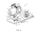
- Figure 3 shows a second embodiment of the mirrorless scanner.
- the scanner 1' of Figure 3 is generally similar to the scanner 1 shown in Figure 1, and like reference numerals indicate corresponding elements of the scanner in each drawing.
- two thin wires 15' connect the leads of the photodiode 31' to the stationary holder 17'.
- the wires 15' are attached to the intermediate fixing point 16 atop the collar 12 in the same manner as the wires 15 from VLD 11.
- the photodiode 31' oscillates with the VLD 11.
- the photodiode 31' is located on the front of the moving assembly 10 directly below the VLD 11.
- the photodiode 31' like VLD 11, oscillates back and forth through a short rotational arc about the axis of shaft 13.
- the receptor photodiode 31' therefore closely tracks the motion of the oscillating emitter, VLD 11.
- the laser diode VLD 11 by itself or the VLD 11 and photodetector 31' turn about an axis to effect a scanning or sweeping action.
- the invention moves a focusing lens mounted in front of the VLD, relative to the VLD in a direction across the path of the beam from the light-emitting outlet of the diode.
- the lens can move alone, in which case the invention includes a fixed aperture stop in front of or behind the lens. Alternately, the aperture stop can be attached to and move with the lens.
- a laser diode 32 is stationarily mounted on a support 122.
- the diode 32 emits light along optical axis 130.
- the emitted light takes the form of a wide-angle fan-shaped laser beam schematically represented by light rays 124, 126.
- the fan-shaped beam diverges at different angles in both orthogonal planes extending parallel to the plane of the diode outlet and perpendicular to the optical axis 130.
- the focusing lens 36 is mounted in a holder 128 at a fixed distance of focal length F as measured along axis 130, from the diode.
- the holder has an opening centered on the axis 130, the opening serving as the aperture stop 38.
- a voice coil 138 surrounds the holder 128 inside the casing 132 and is between the north N and south S poles of the magnet casing.
- the holder and, in turn, the lens and the aperture stop are made to jointly reciprocate back and forth in a plane perpendicular to axis 130 due to electromagnetic attraction and repulsion forces generated at the coil.
- D the deflection of the lens and aperture stop as measured from the axis 130 to one end- limiting position
- Figure 6 shows an alternate to the convoluted springs 134, 136.
- a so-called “spider” spring 142 having curved legs 144 could also be used.
- Figure 7 shows another arrangement for reciprocally shifting the lens 36 and aperture stop 38 in a plane parallel to the plane of the outlet of the diode 32.
- the lens 36 is mounted on a bridge support 150 (shown in Figure 9) which spans the distance between, and is carried by, two center legs 152, 154 of E-shaped leaf springs 156, 158 (see Figure 8).
- Outer legs 160, 162 of spring 156 and outer legs 164, 166 of spring 158 are stationarily connected to an overhead support frame 170.
- the bridge support 150 has an opening centered on optical axis 130, the opening serving as the aperture stop 38.
- a permanent magnet strip 172 having a north N pole at one end and a south S pole at an opposite end is carried by the bridge support.
- a pair of driving coils 174, 176 surrounds each pole.
- each driving coil is electrically energized. Electromagnetic attraction and repulsion forces are generated by magnetic interaction between the coils and the poles N, S, thereby causing the bridge support to be reciprocally shifted in a plane perpendicular to axis 130.
- Figure 9 shows this arrangement in a center, non-shifted position.
- the Figure 10 embodiment described below illustrates a shifted position. It will be noted that only the upper ends of the center legs of the E-springs are displaced. A substantially constant distance between the lens and aperture stop combination and the diode is maintained. This arrangement maintains proper laser beam focus at the reference plane throughout the range of reciprocal displacement of the lens.
- the beam spot is moved along an arc around a center of curvature at the lens. It is possible, by having unequal lengths or stiffnesses in the legs of the springs, to have the beam spot moved in a desired manner across the symbol. For example, the spot can be moved in a straight line.
- Figure 10 shows an arrangement identical to Figure 9, but, instead of the magnetic strip 172, a plate 180 is connected to the bridge support.
- the plate 180 has a lug 182 to which a drive bar 184 is pivotably connected.
- the bar 184 can be connected to a pure mechanical drive, an electro-mechanical drive, or a piezo-electric substrate, i.e., a transducer operative for converting electrical to mechanical energy, to effect the reciprocal movement.
- the center legs 152, 154 of the springs can be made of one bi-metallic material while the outer legs are made of another bi-metallic material. Heating all the legs would cause the center legs to be displaced relative to the outer legs.
- FIG 11 Another approach is shown in Figure 11, wherein the aperture stop 38 is held stationary at a point between the lens 36 and the laser diode 32, and only the focusing lens 36 is reciprocally shifted. Since the laser beam does not pass through the center of the lens 36 when the lens is shifted off axis, the deflection or scan angle A is amplified. Light passing through the lens off the axis 130 has more optical aberrations, but they have not been found to be significant for bar code reading applications.
- the low mass of the moving structure i.e., the lens alone; the lens and aperture stop together; the lens, aperture stop and diode jointly; and the lens, aperture stop, diode and photodetector jointly, enables the system to operate at resonance for low power applications, as well as off resonance. Very high scanning speeds on the order of 40 scans per second and more are obtainable due to the low mass of the moving structure.
- the objective lens reciprocates laterally through an arc in front of the light emitter.
- a flexible support structure movably mounts the objective lens in front of the light emitter.
- the flexible support structure consists of two strips of mylar film, but other flexible elements could be used.
- the flexible support provided by the two strips of mylar film permits lateral movement of the objective lens with respect to light from the light emitter.
- the lens is attached between the moveable ends of the two strips, and the opposite ends of the strips are attached to a fixed support point, for example on the scanner chassis. Flexing of the strips therefore causes the lens to move laterally through an arc.
- the objective lens is laterally reciprocated in response to a motive force. Reciprocation of the objective lens through an arc during emission of light by the light emitter causes the light to scan a surface, such as a surface bearing a bar code label.
- the oscillation of the assembly is again provided by the combination of a permanent magnet and an electromagnet.
- a restoring force is provided by the combination of a fixed position core and coil with the moveable permanent magnet.
- the flexible support structure supplies the restorative force, thus eliminating the need for a heavy core for the electromagnetic which comprised a material such as a steel to which the permanent magnet was attracted.
- a condenser lens 211 is placed in a lens holder 213 that is supported by the two pieces of mylar film 215 and 217.
- the circular lens holder 213 is attached to an edge of each of the mylar film strips 215, 217 at the moveable front ends of the strips.
- the lens holders in the embodiments of Figures 7-11 were connected to the flat side of flexible spring strips.
- the opposite ends of the mylar strips 215, 217 are fixed to a chassis 218.
- Figure 12 shows upper and lower clamping blocks 207, 205. At least a portion of the back surface of each block is attached to the chassis 218. Tightening of bolts 206, 204 compresses clamping blocks 207, 205 on the ends of flexible mylar strips 215, 217 to retain the ends of those strips in fixed relation with respect to chassis 218.
- a spring bolt 219 attached to the chassis 218 between the two mylar strips 215, 217 supports a VLD 232 which serves as the light emitter of this scanner.
- An opening 238 through the front of the lens holder 213 serves as the aperture stop.
- a core 221 comprises a bobbin around which the coil 223 is wound such that the core and coil are entirely concentric to minimize size and weight.
- the permanent magnet 225 is glued to the front of the lens holder 213; and an arm 240, attached to the chassis 218, supports the coil 223 and bobbin core 221 of the electromagnet in close proximity to the moveable permanent magnet 225.
- An alternating current signal drives the coil.
- the magnetic field generated by a coil 223 applies driving force to the permanent magnet 225.
- a laser beam from the VLD 232 mounted behind the condenser lens is deflected by the reciprocation of the condenser lens 211 when the alternating current applied to the coil causes the permanent magnet to vibrate.
- the beam deflection angle can be as large as ⁇ 20 ° .
- the core 221 need not be made of a soft steel, as in the IMM discussed above.
- the core 221 may consist of any appropriate light weight material.
- the mylar strips 215, 217 bend back and forth causing the lens 211 to reciprocate through an arc.
- the radius of the arc equals the distance between the lens 211 and the point at which clamping blocks first retain the ends of strips 215 and 217.
- the fixed end or center of the radius of curvature will correspond to the front surface of the clamping blocks 205, 207.
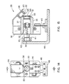
- Figures 14 and 15 show a mirrorless two-dimensional scanning device which is a logical further development of the one-dimensional scanning device shown in Figures 12 and 13.
- the entire chassis 318 and movable lens assembly 350 similar to the entire assembly shown in Figures 12 and 13, is movably supported by at least one flexible support, such as another strip of mylar film.
- An additional magnet/coil assembly is used to push the single lens system back and forth in a second direction, different from the movement direction produced by the first assembly.
- the two directions of reciprocal motion form the raster scan pattern.
- the embodiment of Figures 14 and 15 comprises a fixed chassis 410 and a moveable assembly 350.
- the moveable assembly 350 is essentially similar to the entire embodiment of Figures 12 and 13, but the moveable assembly 350 is mounted on a flexible strip of mylar film 415.
- the objective condenser lens 311 is placed in a lens holder 313 that is supported by the two pieces of mylar film 315 and 317.
- the lens holder 313 is attached to edges of the strips 315, 317 at the front ends of the strips.
- the opposite ends of the mylar strips 315, 317 are fixed to the chassis 318 of the moveable assembly 350.
- the mylar strips 315, 317 are oriented to flex in a direction permitting the lens to reciprocate through a horizontal arc left to right in Figure 14.
- a spring bolt 319 attached to the chassis 318 between the two mylar strips 315 and 317 supports a VLD 332 which serves as the light emitter of this scanner.
- the film strip 415 supporting the moveable assembly 350 is oriented to flex in a direction permitting reciprocation left to right in Figure 15. As the film strip 415 flexes, the entire assembly 350 rotates through a short arc, which causes the emitted beam of light to scan in a vertical direction.
- a core 321 comprises a bobbin around which the coil 323 is wound such that the core and coil are entirely concentric to minimize size and weight.
- the permanent magnet 325 is glued to the lens holder 313 and/or the front of mylar film strip 317.
- An arm 340 attached to the chassis 318 of the moveable assembly 350, supports the coil 323 and bobbin core 321 of the electromagnet in close proximity to the moveable permanent magnet 325.
- the core 321 may consist of any appropriate light weight material.
- the current applied to the coil takes the form of a cyclical AC signal, such as a sign wave, a pulse signal, a triangular wave, etc.
- the induced magnetic forces will produce an oscillatory movement of the permanent magnet 325 and the attached objective condenser lens in the horizontal direction left to right in Figure 14.
- the mylar strips 315, 317 bend back and forth causing objective lens 311 to reciprocate through an arc.
- a core 421 also comprises a bobbin around which the coil 423 is wound such that the core and coil are entirely concentric to minimize size and weight.
- the permanent magnet 425 is glued to the back of the chassis 418 of the moveable assembly 350.
- the fixed position chassis 410 supports the coil 423 and bobbin core 421 of the electromagnet in close proximity to the moveable permanent magnet 425.
- the core 421 may consist of any appropriate light weight material.
- the resilient nature of the mylar film strip 415 causes the assembly 350 to return to its rest position (vertical position as shown in Figure 15).
- a current is introduced through the coil 423, interaction between magnetic fields of the coil and the permanent magnet 425 creates a force causing the magnet 425 (with the attached assembly 350) to move from an equilibrium position, either toward or away from the bobbin and coil.
- a spring force is produced by the mylar strip 415 which is trying to bring the permanent magnet 425 and the assembly 350 back to the vertical rest position. Reversing the polarity of the applied current will reverse the directions of the magnetic force.
- the current applied to the coil 423 takes the form of a cyclical AC signal, such as a sign wave, a pulse signal, a triangular wave, etc.
- the induced magnetic forces will produce an oscillatory movement of the permanent magnet 425 and the attached objective condenser lens 311 within the moveable assembly 350 in the front to back direction of Figure 15.
- Figure 16 illustrates the effect of automatic compensation of variations of beam spot size as a laser beam is scanning over a bar code symbol on a flat plane.
- the VLD emits a beam of light along or parallel to the optical axis of the objective lens.
- the lens focuses the beam of light to a point a distance beyond the lens. Any movement of the optical axis of the lens, i.e. by moving the lens, will produce a corresponding movement of the focused beam and its focal point, as long as the beam from the VLD remains within the lens aperture.
- the planar movement of the lens provided by the embodiments of Figures 4-11 will produce a flat planar scanning of the focused beam over the information surface, e.g. the bar code.
- the arcuate movement of the lens in the embodiments of Figures 12-15 produces a curved scan field, such as shown in Figure 17.
- Lasers emit a narrow core of radiation referred to as the laser beam.
- the beam cross-section varies as the laser beam propagates, particularly after focusing thereof by a lens.
- the flat planar scanning produced by the embodiments of Figures 4-11 maintains an essentially constant beam spot size across the length of the surface scanned. For example, if the surface is spaced from the lens by the focal length of the lens, the waist of the beam will appear at the surface, and as the lens moves the waist will remain on the surface throughout the scan. Scanning which produces a curved scan field, however, will cause the focal point and waist of the beam to move in and out of the plane of the surface of the information being scanned. As a result, the diameter of the beam at the point where it impacts on the surface changes along the scan. Also, because the beam impacts on the surface at an increasing angle as it approaches the outer ends of the scan, the impact spots elongates.
- the focal length of the lens would be the radius of the curved scan field of the beam waist, and Z represents the distance between the beam waist and the information plane.
- the waist is in front of the information plane, and a wider unfocused portion of the beam impacts the information surface at a large angle. Consequently, the impact spot is large.
- the focal point and waist would be behind the surface of the information. Again, a less focused point of the beam actually impacts the surface.
- z at the center is smaller in magnitude than z at the ends of the scan so that the impact spot is smaller in the center, but the center point spot is still larger than would be produced by the impact of the waist itself.
- the waist passes through the surface of the information at points between the center and each end of the scan. At these points, the impact spot is smallest. As shown by the graph shown in Figure 16B, the arcuate scanning field produces a substantial variation in spot size from the center to each end of the scan.
- FIGS 18 and 19 show another embodiment of the invention which is similar to the embodiemnt shown in Figures 12 and 13.
- the laser diode 532 is seated in a laser holder 542, which comprises two aluminum plates 542a and 542b. Screws 543a and 543b clamp the plates 542a and 542b together around diode 532. The screws 543a and 543b also clamp the mylar films 515 and 517 between the plates 542a and 542b.
- a lens holder 513 is glued to the opposite ends of the mylar films 515 and 517.
- the lens holder 513 supports a plastic lens 511.
- An opening 538 through the lens holder 513 serves as the aperture stop.
- the mylar film 517 also supports a permanent magnet 525, which is glued to front end of that film and/or to the lens holder 513.
- a soft-iron core 521 stands on the chassis 540 and serves as a bobbin around which coil 523 is wound.
- the chassis 540 and the laser holder 542 are glued together.
- the magnetic field generated by coil 523 during application of an alternate current produces an oscillating force on the permanent magnet 525. This oscillating force causes the magnet 525 and the attached lens 511 and holder 513 to reciprocate with respect to the laser diode 532 retained by holder 542.
- plastic optics are sensitive to temperature change due to the illumination of a laser beam.
- the plastic optics move like a fan whenever the laser beam is on. This movement dissipates the heat from the beam to the air.
- a large aperture stop (1.5mm) has been used.
- the large aperture stop reduces the influence from variations in beam truncation on the throughput of the scan module. Specifically, the large aperture stop guarantees 0.8mw laser power at the two ends of each scan. Smaller aperture stops result in an increase in working range, but result in a reduced signal to noise ratio of the electronic signal.
- Using a single detector in such embodiments also limits performance of the optical readers using the scanning module. The working range could be increased by using a more complicated receiving configuration.
- Figure 20 illustrates a first embodiment using a fixed aperture stop.
- the embodiment of Figure 20 is essentially identical to that shown in Figure 13.
- the lens holder 213' is entirely open on the front side and does not include a plate through which the aperture stop is formed.
- a plate 239 is fixedly mounted in front of the moveable lens and lens holder.
- the bobbin of the electro-magnet might support the plate 239.
- the aperture stop 238' for this scanning module is formed through the fixed plate 239.
- the condenser lens is a thick lens with a diameter 15mm and central thickness 4mm.
- the mass of this lens is greater than 1 g.
- the linear dimension of the scan module increases 40%.
- the embodiment of Figure 20 still exhibits 22% variation in the throughput due to the well-known cos4 law.
- the fixed aperture can be positioned behind the lens as shown in Figure 21.
- the embodiment of Figure 21 is identical to that of Figure 20, discussed above, except that the plate 239' in which the aperture is formed, is located at a fixed position between the laser diode and the lens.
- an alternative to the condenser lens would be a fresnel lens.
- a fresnel lens is typically smaller and therefore would have a smaller mass to move in response to the applied electromagnetic forces.
- Other micro-optic elements could also be used as the moveable objective lens.
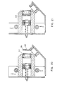
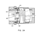
- Figures 22 to 24 are cross sectional views of still further embodiments of the invention wherein the lens, drive magnet assembly and laser diode are all positioned along a common axis and flexible members support the laser diode.
- Significant size reduction allows a module using this type of construction to be installed in a very limited space environments.
- the module shown in Figure 22 comprises an electromagnetic coil 623, a visible laser diode or VLD 632, a permanent ring magnet 625, a condenser lens 611, a flexible member 615 and a lens holder 613 with aperture 638.
- the flex is a flat strip of plastic, such as mylar or kaptan, or a flat strip of non-magnetic metal, for example a berrylium-copper alloy.
- the flex 615 is attached to the front of the bobbin 621 around which the coil 623 is wound.
- the flex 615 supports the cylindrical permanent magnet 625 mounted at the center of the flex.
- the permanent magnet 625 in turn supports the miniature VLD 632 in the center of the magnet.
- the lens holder 613 is installed near the front of the coil 623 and is connected to the coil bobbin 621 via springs.
- the lens holder 613 is a two piece structure.
- the front piece supports the lens 611 and the rear piece connects to the bobbin 621.
- the two pieces of the holder 613 are different in size to allow one piece to telescope into the other, for example by sliding or screw threaded arrangements.
- the distance between the lens 611 and the VLD 632 diminishes. This also changes the distance in front of the module at which the lens 611 focuses the light from the VLD 632.
- a technician telescopes the two pieces of the holder together, against the expansion force provided by the spring, until the module focuses the laser beam at the desired distance in front of the module.
- the technician then attaches the two pieces of the holder 613 together, for example by injecting a transparent glue or by welding the two pieces together.
- the cylindrical permanent magnet is aligned so that the axis between its north and south poles is perpendicular to the axis of coil.
- the axis of magnet 625 could be perpendicular to the plane of Figure 22.
- Figures 23 and 24 are similar to that of Figure 22 discussed above.
- the plastic (or metal) flex 615' is attached to the rear of the bobbin 621'.
- the plastic (or metal) flex 615 is attached to the front of the bobbin 621 around which the coil 623 is wound, as in Figure 22.
- the flex 615 supports a ring member 625' mounted at the center of the flex.
- the ring 625' which supports the miniature VLD 632 may or may not be magnetic.
- a cylindrical magnet 625" is mounted on the rear of the miniature VLD 632.
- a cylindrical magnet could be attached to one side of the flex, and the laser diode fixed to the opposite side of the flex.
- Another arrangement might include a laser diode assembly attached to the flex opposite the magnet.
- Figure 25 shows an embodiment of the invention, similar to that of Figure 1.
- a flat flexible multi-wire cable 15' often referred to as a "flex-cable”
- the "flex-cable” might comprise a flat strip of Kaptan material with wires embedded therein.
- the flexible multi-wire cable 15' provides a durable connection which is not susceptible to breakage due to repeated flexure during oscillation of the laser diode.
- the multi-wire cable provides part or all of the restoring force necessary to operate the device.
- the multi-wire cable can take any of a number of forms and will typically comprise a flexible flat wire cable. Any other flexible flat wire cable could be used so long as the structure provides sufficient flexibility.
- Figure 26 also shows an embodiment of the beam scanner module using a flexible flat wire cable and Figure 27 illustrates a handheld bar code reader incorporating that beam scanner module.
- the handheld arrangement illustrated in Figure 26 comprises a hand-held housing 1250 containing a lightweight, high-speed, miniature scanning motor 1220 similar to that described in U.S. Patent No. 4,496,831.
- the housing 1250 is cylindrical, like the housing of a flashlight or a ball point pen. Because of the small size of the scanning module and associated electronics, the housing 1250 may have a diameter of one inch or less.
- a base 1214 supports the scanning motor 1220.
- a printed circuit board 1248 supports a switch 1262 actuated by depression of trigger 1260, and control circuitry 1224 for providing the drive signals necessary to operate the laser and to control operation of the motor.
- the output shaft 1222 of the motor 1220 extends through an opening in circuit board 1248.
- the motor 1220 repetitively drives output shaft 1222 in alternate circumferential directions over arc lengths less than 360 in each direction about an axis along which the shaft extends.
- U.S. Patent No. 4,496,831 provides structural, functional and operational details of the motor 1220 and of the associated motor control circuitry 1224.
- a U-shaped or circular support structure 1226 is mounted at the end of the shaft 1222 of motor 1220.
- Figure 26 shows a circular support 1226' surrounding the laser emitter and optics assembly 1228.
- a flexible flat wire cable 1215 electrically connects the laser emitter and optics assembly 1228 to circuit board 1248.
- the U-shaped structure 1226 supports the laser emitter and optics assembly 1228.
- the motor 1220 repetitively drives output shaft 1222 in alternate circumferential directions, the subassembly 1228 and the support structure 1226 jointly oscillate and turn with the shaft 1222.
- the subassembly 1228 includes an elongated hollow tube 1230, a laser diode 1232 fixedly mounted at one axial end region of the tube 1230, and a lens barrel 1234 mounted at the opposite axial end region of the tube 1230.
- the lens barrel contains a focusing lens (not shown); and the lens barrel may provide an aperture stop, if necessary, to define the beam diameter and thereby the effective sensing spot of the scanner.
- the focusing lens is preferably a plano-convex lens, but may be spherical, convex or cylindrical.
- U.S. Patent No. 4,816,660 describes the subassembly 1228 in detail.
- the solid state laser diode 1232, of the subassembly 1228 generates an incident laser beam, either in the invisible or visible light range.
- the lens focuses the laser beam such that the beam cross-section or beam spot will have a certain waist size at distances within a working range relative to the housing 1250.
- the focused beam passes along path A through the window 1252; and during the alternate, repetitive oscillations of the shaft 1222, as the support 1226 and the subassembly 1228 concurrently oscillate, the beam spot sweeps in an arc across the encoded information or bar code symbol.
- Photodetector 1244 senses the variable intensity of the returning portion of the reflected laser light and generates an electrical analog signal indicative of the detected variable light intensity.
- the photodetector 1244 is stationarily mounted on the circuit board 1246, but could be mounted on the support structure 1226 for oscillation with the laser and optics subassembly 1228.
- Printed circuit boards 1248 and 1250 on either side of the board 1246, contain signal processing circuitry 1252 and microprocessor circuitry 1253 for converting the analog electrical signal to a digital pulse signal and for deriving data representative of scanned bar code symbols from the digital pulse signal.
- a multi-wire cable 1254 electrically connects the signal processing circuitry and the microprocessor.
- the printed circuit board 1248 may contain the signal processing circuitry and the microprocessor control circuitry.
- a battery pack 1258 mounted at the rear of housing 1250, supplies power for the scanning motor and all circuitry of the handheld bar code scanner arrangement.
- the user points the tip of the scanner at the information and activates the trigger button 1260.
- the laser diode 1232 emits a beam which scans the encoded information, and the photodetector 1244 outputs an analog electrical signal representative of any scanned symbols.
- a digitizer provided within signal processing circuitry 1252 processes the analog signal to produce a pulse signal where the widths and spacings between the pulses correspond to the widths of the bars and the spacings between the bars.
- the pulse signal from the digitizer is applied to the microprocessor 1253 for decoding.
- the microprocessor decoder first determines the pulse widths and spacings of the signal from the digitizer and then analyzes the widths and spacings to find and decode a legitimate bar code message.
- a cable carries the digital data representing the decoded characters to an associated computer or terminal (not shown).
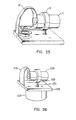
- Figures 28 and 29 show gun shaped moving spot optical scanners for reading bar codes.
- the version illustrated in Figure 28 uses a scanning module 1159 corresponding to the embodiment of Figure 13, and the version illustrated in Figure 29 uses a scanning module 1159' corresponding to the embodiment of Figure 23.
- the bar code reader unit 1100 comprises a light weight plastic housing 1155 in the shape of a gun having a pistol- grip 1153.
- a user activates the light beam 1151 from the scanning module 1159 or 1159' by actuating trigger switch 1154.
- the gun shaped housing contains the scanning module 1159 or 1159' which produces the light beam 1151 and a photodetector 1158 for sensing reflected light.
- Batteries 1162, mounted within the pistol grip 1153 provide power to all elements of the handheld scanner unit 1100.
- Printed circuit board 1161 is mounted near the rear of housing 1155.
- Printed circuit board 1161 contains control circuitry 1124 for producing the signals to drive the laser diode and the coil of the electro-magnet in the scanning module 1159 or 1159'.
- Printed circuit board 1161 also contains signal processing circuitry 1126 and microprocessor circuitry 1140 for converting the analog electrical signal to a digital pulse signal and for deriving data representative of scanned bar code symbols from the digital pulse signal.
- a light transmissive window 1156 in the front end of the housing 1155 allows the outgoing light beam 1151 to exit and the incoming light 1152 reflected from symbol 1170 to enter.
- the reader 1100 is designed such that the user aims the gun shaped device at a bar code symbol from a position at which there is a space between the reader 1100 and symbol 1170.
- the front of the reader 1100 does not touch the surface on which symbol 1170 is formed. Instead, the operation of the scanning module 1159 or 1159' causes the beam to scan across the symbol.
- the light from the diode within the scanning module 1159 or 1159' is typically in the visible light portion of the spectrum. As a result, the user can see the light from the source within the module as the beam scans across the surface on which the symbol 1170 is formed. The user employs this visible light to accurately aim the reader 1100 at the symbol.
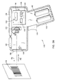
- the reader 1100 may also function as a portable computer terminal, and in such embodiments would include a keyboard 1148 and a display 1149, as described in U.S. Patent No. 4,409,470.
- Figures 27 to 29 show two different configurations of moving spot optical scanners for reading bar codes incorporating three selected embodiments of the scanning modules disclosed herein.
- the various scanning modules disclosed herein each can be used in either of the disclosed configurations or in a wide variety of other optical scanner configurations.
- the mirrorless scanners of the present invention provide a particularly small, light weight, durable, optical scanner.
- the objective lens scanning automatically compensates for variations in beam spot size.
- optical scanning device comprising:
Landscapes
- Physics & Mathematics (AREA)
- Engineering & Computer Science (AREA)
- Electromagnetism (AREA)
- General Physics & Mathematics (AREA)
- Theoretical Computer Science (AREA)
- Health & Medical Sciences (AREA)
- General Health & Medical Sciences (AREA)
- Toxicology (AREA)
- Artificial Intelligence (AREA)
- Computer Vision & Pattern Recognition (AREA)
- General Engineering & Computer Science (AREA)
- Computer Hardware Design (AREA)
- Human Computer Interaction (AREA)
- Business, Economics & Management (AREA)
- Microelectronics & Electronic Packaging (AREA)
- Computer Networks & Wireless Communication (AREA)
- Accounting & Taxation (AREA)
- Strategic Management (AREA)
- General Business, Economics & Management (AREA)
- Mechanical Optical Scanning Systems (AREA)
- Optical Head (AREA)
- Facsimile Heads (AREA)
- Supporting Of Heads In Record-Carrier Devices (AREA)
- Geophysics And Detection Of Objects (AREA)
Applications Claiming Priority (2)
| Application Number | Priority Date | Filing Date | Title |
|---|---|---|---|
| US07/897,664 US5374817A (en) | 1988-05-11 | 1992-06-12 | Pre-objective scanner with flexible optical support |
| US897664 | 1992-06-12 |
Publications (3)
| Publication Number | Publication Date |
|---|---|
| EP0574004A2 true EP0574004A2 (de) | 1993-12-15 |
| EP0574004A3 EP0574004A3 (en) | 1994-08-17 |
| EP0574004B1 EP0574004B1 (de) | 2000-08-30 |
Family
ID=25408226
Family Applications (1)
| Application Number | Title | Priority Date | Filing Date |
|---|---|---|---|
| EP93109378A Expired - Lifetime EP0574004B1 (de) | 1992-06-12 | 1993-06-11 | Abtastmodul für optische Abtastgeräte zum Lesen optischer Informationen |
Country Status (8)
| Country | Link |
|---|---|
| US (4) | US5374817A (de) |
| EP (1) | EP0574004B1 (de) |
| JP (1) | JPH06176182A (de) |
| KR (1) | KR940006052A (de) |
| CN (1) | CN1038537C (de) |
| AT (1) | ATE196025T1 (de) |
| DE (1) | DE69329312T2 (de) |
| ES (1) | ES2149184T3 (de) |
Cited By (1)
| Publication number | Priority date | Publication date | Assignee | Title |
|---|---|---|---|---|
| EP1164601A3 (de) * | 2000-06-16 | 2002-07-24 | Canon Kabushiki Kaisha | Elektromagnetischer Betätiger, zugehöriges Herstellungsverfahren sowie mit einem solchen Betätiger versehener optischer Abtaster |
Families Citing this family (39)
| Publication number | Priority date | Publication date | Assignee | Title |
|---|---|---|---|---|
| US5374817A (en) * | 1988-05-11 | 1994-12-20 | Symbol Technologies, Inc. | Pre-objective scanner with flexible optical support |
| US5665954A (en) * | 1988-10-21 | 1997-09-09 | Symbol Technologies, Inc. | Electro-optical scanner module having dual electro-magnetic coils |
| US5280165A (en) * | 1989-10-30 | 1994-01-18 | Symbol Technolgoies, Inc. | Scan pattern generators for bar code symbol readers |
| US5504316A (en) * | 1990-05-08 | 1996-04-02 | Symbol Technologies, Inc. | Laser scanning system and scanning method for reading 1-D and 2-D barcode symbols |
| US6575370B1 (en) * | 1990-05-08 | 2003-06-10 | Symbol Technologies, Inc. | Electro-optical scanning assembly with one-piece, oscillatable, focusing/scan element |
| US6742709B2 (en) | 1990-09-11 | 2004-06-01 | Metrologic Instruments, Inc. | Bar code symbol reading system employing electronically-controlled raster-type laser scanner for reading bar code symbols during hands-on and hands-free modes of operation |
| US6874689B2 (en) * | 1990-09-11 | 2005-04-05 | Metrologic Instruments, Inc. | Laser beam scanning device employing a scanning element having a flexible photo-etched gap region disposed between an anchored base portion and a light beam deflecting portion having a natural frequency of oscillation tuned by the physical dimensions of said flexible photo-etched gap region and forcibly oscillated about a fixed pivot point at an electronically-controlled frequency of oscillation substantially different from said natural resonant frequency of oscillation |
| US6073846A (en) * | 1994-08-17 | 2000-06-13 | Metrologic Instruments, Inc. | Holographic laser scanning system and process and apparatus and method |
| JP3379837B2 (ja) * | 1994-10-27 | 2003-02-24 | 富士通株式会社 | 光学読取装置 |
| EP0735361B1 (de) * | 1995-03-31 | 2006-05-31 | LINTEC Corporation | Vorrichtung zur Prüfung von Halbleitersubstraten |
| IL115477A0 (en) * | 1995-10-01 | 1996-01-19 | Kaplan Harel Holdings Ltd | Scanner |
| US6152372A (en) * | 1996-09-23 | 2000-11-28 | Psc Scanning, Inc. | Dithering assemblies for barcode scanners |
| US6166375A (en) | 1996-10-08 | 2000-12-26 | Psc Scanning, Inc. | Offset optical axes for bar code scanner |
| DE69732565T2 (de) * | 1997-07-18 | 2006-01-12 | Datalogic S.P.A., Lippo Di Calderara Di Reno | Vorrichtung und Verfahren zum Lesen eines optischen Codes |
| US7124950B2 (en) * | 1997-09-16 | 2006-10-24 | Metrologic Instruments, Inc. | Bar code symbol reading system employing electronically-controlled raster-type laser scanner for reading bar code symbols during on hands-on and hands-free modes of operation |
| US6098886A (en) * | 1998-01-21 | 2000-08-08 | Symbol Technologies, Inc. | Glove-mounted system for reading bar code symbols |
| JP3952614B2 (ja) * | 1998-11-26 | 2007-08-01 | 株式会社デンソー | 光学的読取装置 |
| JP2000206444A (ja) * | 1999-01-19 | 2000-07-28 | Sankyo Seiki Mfg Co Ltd | ビ―ム走査装置 |
| US6497193B2 (en) | 1999-06-07 | 2002-12-24 | Neocera, Inc. | Scanned focus deposition system |
| DE29919989U1 (de) * | 1999-11-15 | 2000-02-17 | Leuze Electronic Gmbh + Co, 73277 Owen | Optoelektronische Vorrichtung |
| US6820812B2 (en) * | 2002-11-04 | 2004-11-23 | Symbol Technologies, Inc. | Battery integrated into a mobile device |
| US7823783B2 (en) | 2003-10-24 | 2010-11-02 | Cognex Technology And Investment Corporation | Light pipe illumination system and method |
| US9070031B2 (en) | 2003-10-24 | 2015-06-30 | Cognex Technology And Investment Llc | Integrated illumination assembly for symbology reader |
| US7823789B2 (en) | 2004-12-21 | 2010-11-02 | Cognex Technology And Investment Corporation | Low profile illumination for direct part mark readers |
| US7874487B2 (en) * | 2005-10-24 | 2011-01-25 | Cognex Technology And Investment Corporation | Integrated illumination assembly for symbology reader |
| US9536124B1 (en) * | 2003-10-24 | 2017-01-03 | Cognex Corporation | Integrated illumination assembly for symbology reader |
| US7604174B2 (en) * | 2003-10-24 | 2009-10-20 | Cognex Technology And Investment Corporation | Method and apparatus for providing omnidirectional lighting in a scanning device |
| NL1026006C2 (nl) * | 2004-04-22 | 2005-10-25 | Fei Co | Deeltjes-optisch apparaat voorzien van lenzen met permanent magnetisch materiaal. |
| US9292724B1 (en) | 2004-12-16 | 2016-03-22 | Cognex Corporation | Hand held symbology reader illumination diffuser with aimer optics |
| US7617984B2 (en) | 2004-12-16 | 2009-11-17 | Cognex Technology And Investment Corporation | Hand held symbology reader illumination diffuser |
| JP5086576B2 (ja) * | 2006-07-27 | 2012-11-28 | 株式会社キーエンス | 光学読取装置 |
| EP2197763A4 (de) * | 2007-09-12 | 2011-04-06 | Biba Pty Ltd | Getränkebehälterträger |
| USD664044S1 (en) * | 2011-12-27 | 2012-07-24 | Biba Pty Ltd. | Carrier for beverages |
| US9461443B2 (en) * | 2014-02-12 | 2016-10-04 | Agilent Technologies, Inc. | Optical system having reduced pointing-error noise |
| CN106334844A (zh) * | 2016-08-04 | 2017-01-18 | 中国科学院长春光学精密机械与物理研究所 | 柔性结构件的加工方法及装置 |
| CN107065122B (zh) * | 2017-06-05 | 2019-02-19 | 中国矿业大学 | 一种光学主镜电磁支承装置及其方法 |
| JP6651110B1 (ja) * | 2019-05-28 | 2020-02-19 | Dolphin株式会社 | 物体検出装置 |
| CN110179208B (zh) * | 2019-06-11 | 2020-12-01 | 安徽一诺青春工业设计有限公司 | 一种用于制鞋生产的真空加热定型设备 |
| CN113050064A (zh) * | 2020-10-15 | 2021-06-29 | 桂林理工大学 | 一种可编程激光扫描轨迹的装置 |
Family Cites Families (105)
| Publication number | Priority date | Publication date | Assignee | Title |
|---|---|---|---|---|
| US1438974A (en) * | 1920-11-13 | 1922-12-19 | Western Electric Co | Piezo-electrical voltage indicator |
| US1980888A (en) * | 1928-09-22 | 1934-11-13 | Adolph A Thomas | Piezo-electric transmitter and recorder |
| US2290529A (en) * | 1941-08-23 | 1942-07-21 | Sr Frank J Black | Device for measuring rotating workpieces |
| US3614677A (en) * | 1966-04-29 | 1971-10-19 | Ibm | Electromechanical monolithic resonator |
| US3508814A (en) * | 1966-12-19 | 1970-04-28 | Aircraft Corp | Flexure mode transducer for optical beam scanning |
| US3544201A (en) * | 1968-01-02 | 1970-12-01 | Gen Telephone & Elect | Optical beam deflector |
| US3532408A (en) * | 1968-05-20 | 1970-10-06 | Bulova Watch Co Inc | Resonant torsional oscillators |
| US3612642A (en) * | 1969-06-27 | 1971-10-12 | Bulova Watch Co Inc | A high-velocity optical scanner including a torsional fork supporting two reflectors |
| US3700304A (en) * | 1970-08-03 | 1972-10-24 | Bulova Watch Co Inc | Optical switch mechanism |
| US3758199A (en) * | 1971-11-22 | 1973-09-11 | Sperry Rand Corp | Piezoelectrically actuated light deflector |
| US3794410A (en) * | 1973-02-20 | 1974-02-26 | Mca Disco Vision | Articulated mirror |
| DE2321211C3 (de) * | 1973-04-26 | 1980-04-17 | Siemens Ag, 1000 Berlin Und 8000 Muenchen | Strahlablenker mit piezoelektrisch angetriebenen schwenkbaren Spiegeln |
| US3981566A (en) * | 1974-09-23 | 1976-09-21 | Eastman Kodak Company | Lever-action mountings for beam steerer mirrors |
| US4025203A (en) * | 1975-12-11 | 1977-05-24 | Eastman Kodak Company | Mirror-type beam steerer having a virtual pivot |
| US3988092A (en) * | 1975-12-15 | 1976-10-26 | Western Electric Company, Inc. | Apparatus for making retractile cords |
| US4170397A (en) * | 1976-12-16 | 1979-10-09 | Decca Limited | Vibratile optical boresight |
| US4185215A (en) * | 1978-05-11 | 1980-01-22 | General Scanning, Inc. | Permanent magnet synchronous motor |
| US4186332A (en) * | 1978-05-22 | 1980-01-29 | General Scanning Inc. | Limited rotation moving iron motor with novel velocity sensing and feedback |
| US4360798A (en) * | 1978-05-31 | 1982-11-23 | Symbol Technologies, Inc. | Portable laser scanning arrangement for and method of evaluating and validating bar code symbols |
| US4251798A (en) * | 1978-05-31 | 1981-02-17 | Symbol Technologies | Portable laser scanning arrangement for and method of evaluating and validating bar code symbols |
| US4230393A (en) * | 1978-07-31 | 1980-10-28 | Mfe Corporation | Two-axis optical scanner |
| DE2936463A1 (de) * | 1979-09-10 | 1981-03-19 | Siemens AG, 1000 Berlin und 8000 München | Vorrichtung zum erzeugen bewegter lichtstrahlengaenge |
| US4370613A (en) * | 1979-10-02 | 1983-01-25 | General Scanning, Inc. | Galvanometer with molded outer layer under hoop stress |
| US4253104A (en) * | 1979-11-23 | 1981-02-24 | General Scanning, Inc. | Strip chart recorder |
| US4329606A (en) * | 1979-12-10 | 1982-05-11 | General Scanning, Inc. | Electric motor construction |
| US4593186A (en) * | 1980-02-29 | 1986-06-03 | Symbol Technologies, Inc. | Portable laser scanning system and scanning methods |
| US4387297B1 (en) * | 1980-02-29 | 1995-09-12 | Symbol Technologies Inc | Portable laser scanning system and scanning methods |
| US4496831A (en) * | 1980-02-29 | 1985-01-29 | Symbol Technologies, Inc. | Portable laser scanning system and scanning methods |
| US4369361A (en) * | 1980-03-25 | 1983-01-18 | Symbol Technologies, Inc. | Portable, stand-alone, desk-top laser scanning workstation for intelligent data acquisition terminal and method of scanning |
| DE3035315C2 (de) * | 1980-09-18 | 1984-07-12 | Erwin Sick Gmbh Optik-Elektronik, 7808 Waldkirch | Piezoelektrische Lichtablenkvorrichtung |
| US4758717A (en) * | 1982-01-25 | 1988-07-19 | Symbol Technologies, Inc. | Narrow-bodied, single-and twin-windowed portable laser scanning head for reading bar code symbols |
| US4736095A (en) * | 1982-01-25 | 1988-04-05 | Symbol Technologies, Inc. | Narrow-bodied, single- and twin-windowed portable laser scanning head for reading bar code symbols |
| US4409470A (en) * | 1982-01-25 | 1983-10-11 | Symbol Technologies, Inc. | Narrow-bodied, single-and twin-windowed portable laser scanning head for reading bar code symbols |
| US4460120A (en) * | 1982-01-25 | 1984-07-17 | Symbol Technologies, Inc. | Narrow bodied, single- and twin-windowed portable laser scanning head for reading bar code symbols |
| US4845350B1 (en) * | 1982-01-25 | 1991-04-30 | Narrow-bodied,single-and twin-windowed portable laser scanning head for reading bar code symbols | |
| US4528533A (en) * | 1982-07-28 | 1985-07-09 | General Scanning, Inc. | Actuator with compensating flux path |
| US4462014A (en) * | 1982-07-28 | 1984-07-24 | General Scanning Inc. | Wide-angle actuator |
| US4525030A (en) * | 1982-08-26 | 1985-06-25 | General Scanning Inc. | Positioner for optical element |
| US4502752A (en) * | 1982-11-08 | 1985-03-05 | General Scanning, Inc. | Resonant actuator for optical scanning |
| US4578571A (en) * | 1983-11-14 | 1986-03-25 | Numa Corporation | Portable bar code scanning device and method |
| DE3342038C1 (de) * | 1983-11-22 | 1985-03-07 | Erhardt & Leimer GmbH, 8900 Augsburg | Vorrichtung zur Erfassung von Kennzeichnungen auf sich bewegenden Kennzeichnungstraegern |
| US4577131A (en) * | 1983-12-29 | 1986-03-18 | Zygo Corporation | Piezoelectric micromotion actuator |
| US4632501A (en) * | 1984-02-16 | 1986-12-30 | General Scanning, Inc. | Resonant electromechanical oscillator |
| US4673876A (en) * | 1984-03-08 | 1987-06-16 | General Scanning, Inc. | Two-element angular positive sensor for rotatable shaft |
| US4607156A (en) * | 1984-03-26 | 1986-08-19 | Symbol Technologies, Inc. | Shock-resistant support structure for use in portable laser scanning heads |
| US4775815A (en) * | 1984-05-15 | 1988-10-04 | Rockwell International Corporation | Shear motor for dynamic mount for laser-beam steering mirror |
| DE3582717D1 (de) * | 1984-05-24 | 1991-06-06 | Commw Of Australia | Abtastvorrichtung der brennpunktflaeche. |
| US4897532A (en) * | 1985-02-28 | 1990-01-30 | Symbol Technologies, Inc. | Portable laser diode scanning head |
| DE3686170T2 (de) * | 1985-02-28 | 1993-03-18 | Symbol Technologies Inc | Tragbarer abtastkopf mit laserdiode. |
| JPS61208641A (ja) * | 1985-03-13 | 1986-09-17 | Olympus Optical Co Ltd | 光学的情報記録再生装置 |
| US4655543A (en) * | 1985-05-08 | 1987-04-07 | General Scanning, Inc. | Mount for attaching an optical element to a rotating shaft |
| GB2175705B (en) * | 1985-05-24 | 1989-04-19 | Stc Plc | Dirigible reflector and mounting made of crystal material |
| DE3601764A1 (de) * | 1986-01-22 | 1987-07-23 | Messerschmitt Boelkow Blohm | Retromodulator |
| US4787546A (en) * | 1986-03-07 | 1988-11-29 | General Scanning, Inc. | Apparatus for automatic threading of a web |
| US4694212A (en) * | 1986-03-21 | 1987-09-15 | General Scanning, Inc. | Magnetic preloading of actuator bearings |
| US4694235A (en) * | 1986-08-01 | 1987-09-15 | General Scanning, Inc. | Capacitive position sensor |
| US4959568A (en) * | 1986-08-05 | 1990-09-25 | General Scanning, Inc. | Dynamically tunable resonant device with electric control |
| US4778233A (en) * | 1986-09-19 | 1988-10-18 | Ateo Corporation | Steering mirror |
| US4797749A (en) * | 1986-11-18 | 1989-01-10 | General Scanning, Inc. | Scanning system with tunable resonant actuator |
| US4763967A (en) * | 1986-11-18 | 1988-08-16 | General Scanning, Inc. | Tunable resonant device |
| US4816920A (en) * | 1986-11-18 | 1989-03-28 | General Scanning, Inc. | Planar surface scanning system |
| US4816661A (en) * | 1986-12-22 | 1989-03-28 | Symbol Technologies, Inc. | Scan pattern generators for bar code symbol readers |
| US4808804A (en) * | 1987-01-28 | 1989-02-28 | Symbol Technologies, Inc. | Bar code symbol readers with variable spot size and/or working distance |
| JPS63206718A (ja) * | 1987-02-23 | 1988-08-26 | Citizen Watch Co Ltd | 光走査装置 |
| US4878721A (en) * | 1987-02-17 | 1989-11-07 | General Scanning, Inc. | Resonant mechanical system |
| US4874215A (en) * | 1987-04-23 | 1989-10-17 | General Scanning, Inc. | Tunable resonant mechanical system |
| US4746095A (en) * | 1987-09-14 | 1988-05-24 | Anderson, Greenwood & Co. | Bonnet lock |
| US5047625A (en) * | 1987-11-04 | 1991-09-10 | Asahi Kogaku Kogyo Kabushiki Kaisha | Optical system of laser beam reader |
| US4871904A (en) * | 1987-12-28 | 1989-10-03 | Symbol Technologies, Inc. | Multidirectional optical scanner |
| US4830496A (en) * | 1988-01-22 | 1989-05-16 | General Scanning, Inc. | Interferometer |
| JP2674777B2 (ja) * | 1988-04-15 | 1997-11-12 | 松下電工株式会社 | 光ビーム走査用スキャナー |
| US5191197A (en) * | 1988-05-11 | 1993-03-02 | Symbol Technologies, Inc. | Arm mounted scanner actuatable by hand movement |
| US5170277A (en) * | 1988-05-11 | 1992-12-08 | Symbol Technologies, Inc. | Piezoelectric beam deflector |
| US5144120A (en) * | 1988-05-11 | 1992-09-01 | Symbol Technologies, Inc. | Mirrorless scanners with movable laser, optical and sensor components |
| US5374817A (en) * | 1988-05-11 | 1994-12-20 | Symbol Technologies, Inc. | Pre-objective scanner with flexible optical support |
| US4902083A (en) * | 1988-05-31 | 1990-02-20 | Reflection Technology, Inc. | Low vibration resonant scanning unit for miniature optical display apparatus |
| US4919500A (en) * | 1988-09-09 | 1990-04-24 | General Scanning, Inc. | Torsion bar scanner with damping |
| US5140144A (en) * | 1988-10-31 | 1992-08-18 | Symbol Technologies, Inc. | Scan board module for laser scanners |
| US4923281A (en) * | 1988-11-01 | 1990-05-08 | Symbol Technologies Inc. | Laser diode focusing module, method of fabricating, and method of using |
| US5015831A (en) * | 1988-11-07 | 1991-05-14 | Photographic Sciences Corporation | Scan modules for bar code readers and the like in which scan elements are flexurally supported |
| JPH02278391A (ja) * | 1989-04-19 | 1990-11-14 | Sumitomo Electric Ind Ltd | 記号読取装置 |
| US5097354A (en) * | 1989-07-27 | 1992-03-17 | Omron Corporation | Beam scanner |
| US5099110A (en) * | 1989-10-30 | 1992-03-24 | Symbol Technologies, Inc. | Power saving scanning arrangement |
| US5121138A (en) * | 1990-05-22 | 1992-06-09 | General Scanning, Inc. | Resonant scanner control system |
| US5097356A (en) * | 1990-06-01 | 1992-03-17 | General Scanning, Inc. | Optical scanner with damped coupling |
| US5115120A (en) * | 1990-06-26 | 1992-05-19 | Photographic Sciences Corporation | Scan modules for bar code readers and in which scan elements are flexurally supported |
| US5150249A (en) * | 1990-07-06 | 1992-09-22 | General Scanning, Inc. | Two-mirror scanner with pincushion error correction |
| US5048904A (en) * | 1990-07-06 | 1991-09-17 | General Scanning, Inc. | Two-mirror scanner with pincushion error correction |
| US5099386A (en) * | 1990-09-20 | 1992-03-24 | General Scanning, Inc. | Variable-capacitance position transducing |
| US5225770A (en) * | 1991-02-25 | 1993-07-06 | General Scanning, Inc. | Moving magnet galvanometers having a varied density winding distribution coil for a desired performance characteristic |
| US5169050A (en) * | 1991-06-03 | 1992-12-08 | General Scanning, Inc. | Wire bonder with improved actuator |
| US5123024A (en) * | 1991-08-06 | 1992-06-16 | General Scanning, Inc. | Apparatus and method for controlling the light intensity of a laser diode |
| US5300756A (en) * | 1991-10-22 | 1994-04-05 | General Scanning, Inc. | Method for severing integrated-circuit connection paths by a phase-plate-adjusted laser beam |
| US5329103A (en) * | 1991-10-30 | 1994-07-12 | Spectra-Physics | Laser beam scanner with low cost ditherer mechanism |
| CA2080784C (en) * | 1991-11-04 | 2003-08-19 | Simon Bard | Compact bar code scanning arrangement |
| WO1993017396A1 (en) * | 1992-02-21 | 1993-09-02 | Spectra-Physics Scanning Systems, Inc. | Bar code scanner |
| US5235180A (en) * | 1992-03-05 | 1993-08-10 | General Scanning, Inc. | Rotary motor having an angular position transducer and galvanometer scanning system employing such motor |
| US5237444A (en) * | 1992-06-26 | 1993-08-17 | General Scanning, Inc. | Optical scanning system |
| US5225923A (en) * | 1992-07-09 | 1993-07-06 | General Scanning, Inc. | Scanning microscope employing improved scanning mechanism |
| US5528411A (en) * | 1993-05-03 | 1996-06-18 | General Scanning Inc. | Resonant scanner |
| US5537109A (en) * | 1993-05-28 | 1996-07-16 | General Scanning, Inc. | Capacitive transducing with feedback |
| US5400132A (en) * | 1993-10-12 | 1995-03-21 | General Scanning | Rectification of a laser pointing device |
| US5576741A (en) * | 1993-12-28 | 1996-11-19 | General Scanning Inc. | Configurable chart recorder |
| US5670779A (en) * | 1995-05-05 | 1997-09-23 | General Scanning | Electro-optical shaft angle transducer having a rotatable refractive optical element |
| US5521740A (en) * | 1995-07-11 | 1996-05-28 | General Scanning, Inc. | Resonant optical scanner |
-
1992
- 1992-06-12 US US07/897,664 patent/US5374817A/en not_active Expired - Lifetime
-
1993
- 1993-05-21 KR KR1019930008852A patent/KR940006052A/ko not_active Ceased
- 1993-06-04 JP JP5133709A patent/JPH06176182A/ja active Pending
- 1993-06-11 ES ES93109378T patent/ES2149184T3/es not_active Expired - Lifetime
- 1993-06-11 CN CN93106782A patent/CN1038537C/zh not_active Expired - Lifetime
- 1993-06-11 EP EP93109378A patent/EP0574004B1/de not_active Expired - Lifetime
- 1993-06-11 AT AT93109378T patent/ATE196025T1/de active
- 1993-06-11 DE DE69329312T patent/DE69329312T2/de not_active Expired - Lifetime
-
1994
- 1994-03-28 US US08/218,959 patent/US5536925A/en not_active Expired - Fee Related
-
1996
- 1996-02-07 US US08/597,882 patent/US5661290A/en not_active Expired - Lifetime
-
1997
- 1997-02-14 US US08/800,610 patent/US5811773A/en not_active Expired - Lifetime
Cited By (3)
| Publication number | Priority date | Publication date | Assignee | Title |
|---|---|---|---|---|
| EP1164601A3 (de) * | 2000-06-16 | 2002-07-24 | Canon Kabushiki Kaisha | Elektromagnetischer Betätiger, zugehöriges Herstellungsverfahren sowie mit einem solchen Betätiger versehener optischer Abtaster |
| US6674350B2 (en) | 2000-06-16 | 2004-01-06 | Canon Kabushiki Kaisha | Electromagnetic actuator, optical scanner and method of preparing electromagnetic actuator |
| US6920681B2 (en) | 2000-06-16 | 2005-07-26 | Canon Kabushiki Kaisha | Method of preparing an electromagnetic actuator using a substrate |
Also Published As
| Publication number | Publication date |
|---|---|
| US5811773A (en) | 1998-09-22 |
| EP0574004A3 (en) | 1994-08-17 |
| US5536925A (en) | 1996-07-16 |
| US5661290A (en) | 1997-08-26 |
| CN1105467A (zh) | 1995-07-19 |
| CN1038537C (zh) | 1998-05-27 |
| KR940006052A (ko) | 1994-03-23 |
| ATE196025T1 (de) | 2000-09-15 |
| JPH06176182A (ja) | 1994-06-24 |
| DE69329312T2 (de) | 2001-04-12 |
| EP0574004B1 (de) | 2000-08-30 |
| DE69329312D1 (de) | 2000-10-05 |
| ES2149184T3 (es) | 2000-11-01 |
| US5374817A (en) | 1994-12-20 |
Similar Documents
| Publication | Publication Date | Title |
|---|---|---|
| EP0574004A2 (de) | Vor dem Objektiv angeordnetes Abtastsystem mit flexiblem optischem Träger | |
| US5404001A (en) | Fiber optic barcode reader | |
| EP0818750B1 (de) | Dünner Abtastermodul | |
| US5422469A (en) | Fiber optic barcode readers using purely mechanical scanner oscillation | |
| US5900617A (en) | Optical scanning module having multiple-sided enclosure | |
| JP3389270B2 (ja) | 小型バーコード走査装置 | |
| EP0930579B1 (de) | Ring scanner | |
| EP0788068B1 (de) | Abtastvorrichtung | |
| US6527183B2 (en) | One piece optical assembly for low cost optical scanner | |
| US5410140A (en) | Mirrorless ring mounted miniature optical scanner | |
| US5479000A (en) | Compact scanning module for reading bar codes | |
| US6491225B1 (en) | Electro-optical reader with electronic stylus | |
| JP2002163601A (ja) | バーコード・リーダーにおけるコンパクトな光学・走査複合モジュール | |
| EP0541065B1 (de) | Kompakte Strichkode-Abtastanordnung | |
| JP2002131686A (ja) | 一体形可振合焦/走査素子を有する電気光学的走査組立体 | |
| EP1308875B1 (de) | Hochgeschwindigkeitslaserabtastmodul mit gefaltetem Strahlengang | |
| EP0624852B1 (de) | Abtastmodul für Symbol-Abtastsystem | |
| GB2387701A (en) | Optical indicia scan module |
Legal Events
| Date | Code | Title | Description |
|---|---|---|---|
| PUAI | Public reference made under article 153(3) epc to a published international application that has entered the european phase |
Free format text: ORIGINAL CODE: 0009012 |
|
| AK | Designated contracting states |
Kind code of ref document: A2 Designated state(s): AT DE ES FR GB IT |
|
| PUAL | Search report despatched |
Free format text: ORIGINAL CODE: 0009013 |
|
| AK | Designated contracting states |
Kind code of ref document: A3 Designated state(s): AT DE ES FR GB IT |
|
| 17P | Request for examination filed |
Effective date: 19950217 |
|
| 17Q | First examination report despatched |
Effective date: 19950825 |
|
| GRAG | Despatch of communication of intention to grant |
Free format text: ORIGINAL CODE: EPIDOS AGRA |
|
| GRAG | Despatch of communication of intention to grant |
Free format text: ORIGINAL CODE: EPIDOS AGRA |
|
| GRAH | Despatch of communication of intention to grant a patent |
Free format text: ORIGINAL CODE: EPIDOS IGRA |
|
| 17Q | First examination report despatched |
Effective date: 19950825 |
|
| RTI1 | Title (correction) |
Free format text: SCAN MODULE FOR OPTICAL SCANNING DEVICES FOR READING OPTICAL INFORMATION |
|
| RAP1 | Party data changed (applicant data changed or rights of an application transferred) |
Owner name: SYMBOL TECHNOLOGIES, INC. |
|
| GRAH | Despatch of communication of intention to grant a patent |
Free format text: ORIGINAL CODE: EPIDOS IGRA |
|
| GRAA | (expected) grant |
Free format text: ORIGINAL CODE: 0009210 |
|
| AK | Designated contracting states |
Kind code of ref document: B1 Designated state(s): AT DE ES FR GB IT |
|
| REF | Corresponds to: |
Ref document number: 196025 Country of ref document: AT Date of ref document: 20000915 Kind code of ref document: T |
|
| ITF | It: translation for a ep patent filed | ||
| REF | Corresponds to: |
Ref document number: 69329312 Country of ref document: DE Date of ref document: 20001005 |
|
| REG | Reference to a national code |
Ref country code: ES Ref legal event code: FG2A Ref document number: 2149184 Country of ref document: ES Kind code of ref document: T3 |
|
| ET | Fr: translation filed | ||
| PLBE | No opposition filed within time limit |
Free format text: ORIGINAL CODE: 0009261 |
|
| STAA | Information on the status of an ep patent application or granted ep patent |
Free format text: STATUS: NO OPPOSITION FILED WITHIN TIME LIMIT |
|
| 26N | No opposition filed | ||
| REG | Reference to a national code |
Ref country code: GB Ref legal event code: IF02 |
|
| REG | Reference to a national code |
Ref country code: DE Ref legal event code: R082 Ref document number: 69329312 Country of ref document: DE Representative=s name: SCHUMACHER & WILLSAU PATENTANWALTSGESELLSCHAFT, DE |
|
| PGFP | Annual fee paid to national office [announced via postgrant information from national office to epo] |
Ref country code: GB Payment date: 20120525 Year of fee payment: 20 Ref country code: FR Payment date: 20120614 Year of fee payment: 20 |
|
| PGFP | Annual fee paid to national office [announced via postgrant information from national office to epo] |
Ref country code: IT Payment date: 20120619 Year of fee payment: 20 |
|
| PGFP | Annual fee paid to national office [announced via postgrant information from national office to epo] |
Ref country code: ES Payment date: 20120622 Year of fee payment: 20 Ref country code: DE Payment date: 20120629 Year of fee payment: 20 |
|
| PGFP | Annual fee paid to national office [announced via postgrant information from national office to epo] |
Ref country code: AT Payment date: 20120525 Year of fee payment: 20 |
|
| REG | Reference to a national code |
Ref country code: DE Ref legal event code: R071 Ref document number: 69329312 Country of ref document: DE |
|
| REG | Reference to a national code |
Ref country code: GB Ref legal event code: PE20 Expiry date: 20130610 |
|
| REG | Reference to a national code |
Ref country code: AT Ref legal event code: MK07 Ref document number: 196025 Country of ref document: AT Kind code of ref document: T Effective date: 20130611 |
|
| PG25 | Lapsed in a contracting state [announced via postgrant information from national office to epo] |
Ref country code: GB Free format text: LAPSE BECAUSE OF EXPIRATION OF PROTECTION Effective date: 20130610 Ref country code: DE Free format text: LAPSE BECAUSE OF EXPIRATION OF PROTECTION Effective date: 20130612 |
|
| REG | Reference to a national code |
Ref country code: ES Ref legal event code: FD2A Effective date: 20130823 |
|
| PG25 | Lapsed in a contracting state [announced via postgrant information from national office to epo] |
Ref country code: ES Free format text: LAPSE BECAUSE OF EXPIRATION OF PROTECTION Effective date: 20130612 |