EP0574076A1 - Sonde zum Abtasten von elektrischen Signalen - Google Patents
Sonde zum Abtasten von elektrischen Signalen Download PDFInfo
- Publication number
- EP0574076A1 EP0574076A1 EP93201577A EP93201577A EP0574076A1 EP 0574076 A1 EP0574076 A1 EP 0574076A1 EP 93201577 A EP93201577 A EP 93201577A EP 93201577 A EP93201577 A EP 93201577A EP 0574076 A1 EP0574076 A1 EP 0574076A1
- Authority
- EP
- European Patent Office
- Prior art keywords
- probe
- input
- resistor
- wire
- output
- Prior art date
- Legal status (The legal status is an assumption and is not a legal conclusion. Google has not performed a legal analysis and makes no representation as to the accuracy of the status listed.)
- Withdrawn
Links
Images


Classifications
-
- H—ELECTRICITY
- H04—ELECTRIC COMMUNICATION TECHNIQUE
- H04B—TRANSMISSION
- H04B3/00—Line transmission systems
- H04B3/02—Details
- H04B3/04—Control of transmission; Equalising
-
- G—PHYSICS
- G01—MEASURING; TESTING
- G01R—MEASURING ELECTRIC VARIABLES; MEASURING MAGNETIC VARIABLES
- G01R1/00—Details of instruments or arrangements of the types included in groups G01R5/00 - G01R13/00 and G01R31/00
- G01R1/02—General constructional details
- G01R1/06—Measuring leads; Measuring probes
-
- G—PHYSICS
- G01—MEASURING; TESTING
- G01R—MEASURING ELECTRIC VARIABLES; MEASURING MAGNETIC VARIABLES
- G01R1/00—Details of instruments or arrangements of the types included in groups G01R5/00 - G01R13/00 and G01R31/00
- G01R1/20—Modifications of basic electric elements for use in electric measuring instruments; Structural combinations of such elements with such instruments
- G01R1/24—Transmission-line, e.g. waveguide, measuring sections, e.g. slotted section
Definitions
- This method can easily be extended to the calculation of a line according to the invention formed by several resistances connecting several sections of line without loss.
- the comparators do not all have identical input characteristics and there generally appears to be dispersions in particular on the input capacitors or the connection reactors (input pins). It is possible to correct a channel independently of another channel by placing a circuit 42 with programmable capacities at the input of the channel comparator (FIG. 5). By thus compensating for the dispersions between the channels, it is possible to obtain that each channel can be determined to have a frequency response in accordance with the desired characteristics.
- FIG. 6 shows an example of a circuit 42 with programmable capacities. Between a supply line V and a reference G (ground), there is in parallel a battery of capacities C1, C, ... C n , each in series with a MOS transistor T1, T2 ...
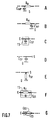
- Correction elements can also be placed in parallel on the resistor R E : for example capacitance C ES (FIG. 7F). To suppress a continuous level, it is also possible to place a capacitor C ES on the input terminal E in series with the carrying wire ( Figure 7G).
Landscapes
- Physics & Mathematics (AREA)
- General Physics & Mathematics (AREA)
- Engineering & Computer Science (AREA)
- Computer Networks & Wireless Communication (AREA)
- Signal Processing (AREA)
- Measuring Leads Or Probes (AREA)
Applications Claiming Priority (2)
| Application Number | Priority Date | Filing Date | Title |
|---|---|---|---|
| FR9206986 | 1992-06-10 | ||
| FR9206986A FR2692359A1 (fr) | 1992-06-10 | 1992-06-10 | Sonde pour prélever des signaux électriques. |
Publications (1)
| Publication Number | Publication Date |
|---|---|
| EP0574076A1 true EP0574076A1 (de) | 1993-12-15 |
Family
ID=9430582
Family Applications (1)
| Application Number | Title | Priority Date | Filing Date |
|---|---|---|---|
| EP93201577A Withdrawn EP0574076A1 (de) | 1992-06-10 | 1993-06-02 | Sonde zum Abtasten von elektrischen Signalen |
Country Status (3)
| Country | Link |
|---|---|
| EP (1) | EP0574076A1 (de) |
| JP (1) | JPH0634656A (de) |
| FR (1) | FR2692359A1 (de) |
Families Citing this family (2)
| Publication number | Priority date | Publication date | Assignee | Title |
|---|---|---|---|---|
| JP5071086B2 (ja) * | 2007-12-13 | 2012-11-14 | 横河電機株式会社 | パッシブプローブ装置 |
| JP4957645B2 (ja) * | 2008-05-12 | 2012-06-20 | 株式会社島津製作所 | 材料試験機 |
Citations (3)
| Publication number | Priority date | Publication date | Assignee | Title |
|---|---|---|---|---|
| FR2376416A1 (fr) * | 1976-12-28 | 1978-07-28 | Thomson Csf | Dispositif de mesure a large bande et materiel de mesure comportant un tel dispositif |
| EP0427521A2 (de) * | 1989-11-06 | 1991-05-15 | Woven Electronics Corporation | Verfahren und elektrischer Kabelanschluss für Signalmessgerät |
| EP0437885A2 (de) * | 1990-01-18 | 1991-07-24 | Philips Patentverwaltung GmbH | Frequenzgangentzerrer |
Family Cites Families (1)
| Publication number | Priority date | Publication date | Assignee | Title |
|---|---|---|---|---|
| JPS57127862A (en) * | 1981-01-31 | 1982-08-09 | Hitachi Ltd | Tester apparatus |
-
1992
- 1992-06-10 FR FR9206986A patent/FR2692359A1/fr not_active Withdrawn
-
1993
- 1993-06-02 EP EP93201577A patent/EP0574076A1/de not_active Withdrawn
- 1993-06-07 JP JP13596493A patent/JPH0634656A/ja active Pending
Patent Citations (3)
| Publication number | Priority date | Publication date | Assignee | Title |
|---|---|---|---|---|
| FR2376416A1 (fr) * | 1976-12-28 | 1978-07-28 | Thomson Csf | Dispositif de mesure a large bande et materiel de mesure comportant un tel dispositif |
| EP0427521A2 (de) * | 1989-11-06 | 1991-05-15 | Woven Electronics Corporation | Verfahren und elektrischer Kabelanschluss für Signalmessgerät |
| EP0437885A2 (de) * | 1990-01-18 | 1991-07-24 | Philips Patentverwaltung GmbH | Frequenzgangentzerrer |
Non-Patent Citations (1)
| Title |
|---|
| PATENT ABSTRACTS OF JAPAN vol. 6, no. 225 (P-154)(1103) 10 Novembre 1982 & JP-A-57 127 862 ( HITACHI ) * |
Also Published As
| Publication number | Publication date |
|---|---|
| JPH0634656A (ja) | 1994-02-10 |
| FR2692359A1 (fr) | 1993-12-17 |
Similar Documents
| Publication | Publication Date | Title |
|---|---|---|
| FR3028691B1 (fr) | Procede et module d'adaptation automatique d'impedance, en particulier pour une chaine d'emission ou reception radiofrequence | |
| EP2037576B1 (de) | Verfahren zur automatischen Impedanzanpassung einer Radiofrequenzschaltung und einer Funksender- oder -empfangskette mit automatischer Anpassung | |
| CA1299661C (fr) | Dispositif de mesure de produits d'intermodulation d'un systeme recepteur | |
| EP0403344A1 (de) | Messanordnung für Oberflächen-Widerstand | |
| FR2949922A1 (fr) | Procede d'adaptation d'impedance d'antenne multibandes et chaine d'emission ou reception a adaptation automatique. | |
| EP0238124B1 (de) | Hochfrequenzdämpfungsglied mit hoher Eingangsimpedanz und mehrfachem Eichmassverfahren, Anwendung desselben in einer aktiven Messsonde und bei einem Oszilloskop | |
| FR2583169A1 (fr) | Procede et appareil de mesure de capacite | |
| EP3182588B1 (de) | Automatische anpassung der impedanz eines funkempfängers | |
| EP0523221B1 (de) | Verfahren zum messen der temperatur eines materials unter verwendung von mikrowellenstrahlung | |
| CA2419079A1 (fr) | Procede et dispositif de mesure de l'attenuation d'une ligne | |
| EP2368095A2 (de) | Einrichtung zum quantifizieren und lokalisieren eines mit einer vorbestimmten frequenz modulierten lichtsignals | |
| EP2452394A1 (de) | In eine leiterplatte integrierter wilkinson-leistungsteiler und mikrowellenanordnung mit einem solchen leistungsteiler | |
| FR2491283A1 (fr) | Transformateurs a circuit imprime | |
| EP0463964B2 (de) | Anlage zur Erzeugung und zum Empfang von Ultraschall | |
| EP0574076A1 (de) | Sonde zum Abtasten von elektrischen Signalen | |
| FR2862758A1 (fr) | Capteur et ensemble de mesures hydrometriques | |
| EP0492392B1 (de) | Gerät zur zerstörungsfreien Prüfung mit Wirbelströmen | |
| WO2002046780A1 (fr) | Dispositif de caracterisation electromagentique d'une structure sous test | |
| EP0003450B1 (de) | Messeinrichtung für den Hyperfrequenzbereich und Generator mit einer solchen Einrichtung | |
| FR2690019A1 (fr) | Circuit et mélangeur harmoniques. | |
| EP0982855A1 (de) | Verfahren und Vorrichtung zur Spektralanalyse von Funksignalen eines Funkkommunikationsystems | |
| FR2598516A1 (fr) | Procede et dispositif de mesure de l'impedance d'une electrode de terre en fonction de la frequence | |
| FR2556102A1 (fr) | Appareil de mesure de la symetrie d'impedance par rapport a la terre d'un equipement de telecommunication a paires symetriques | |
| FR2713847A1 (fr) | Adaptateur pour antenne radio avec circuit d'aiguillage pour au moins deux bandes de fréquence. | |
| FR2878375A1 (fr) | Coupleur actif 90 a tres large bande |
Legal Events
| Date | Code | Title | Description |
|---|---|---|---|
| PUAI | Public reference made under article 153(3) epc to a published international application that has entered the european phase |
Free format text: ORIGINAL CODE: 0009012 |
|
| AK | Designated contracting states |
Kind code of ref document: A1 Designated state(s): DE FR GB NL |
|
| 17P | Request for examination filed |
Effective date: 19940530 |
|
| RAP1 | Party data changed (applicant data changed or rights of an application transferred) |
Owner name: N.V. PHILIPS' GLOEILAMPENFABRIEKEN Owner name: LABORATOIRES D'ELECTRONIQUE PHILIPS |
|
| STAA | Information on the status of an ep patent application or granted ep patent |
Free format text: STATUS: THE APPLICATION HAS BEEN WITHDRAWN |
|
| 18W | Application withdrawn |
Withdrawal date: 19950925 |