EP0574130B1 - Verrouillage de sûreté entre attelage et reinage à air comprimé - Google Patents
Verrouillage de sûreté entre attelage et reinage à air comprimé Download PDFInfo
- Publication number
- EP0574130B1 EP0574130B1 EP93303494A EP93303494A EP0574130B1 EP 0574130 B1 EP0574130 B1 EP 0574130B1 EP 93303494 A EP93303494 A EP 93303494A EP 93303494 A EP93303494 A EP 93303494A EP 0574130 B1 EP0574130 B1 EP 0574130B1
- Authority
- EP
- European Patent Office
- Prior art keywords
- air
- valve
- braking system
- brake
- coupling
- Prior art date
- Legal status (The legal status is an assumption and is not a legal conclusion. Google has not performed a legal analysis and makes no representation as to the accuracy of the status listed.)
- Expired - Lifetime
Links
Images
Classifications
-
- B—PERFORMING OPERATIONS; TRANSPORTING
- B61—RAILWAYS
- B61D—BODY DETAILS OR KINDS OF RAILWAY VEHICLES
- B61D3/00—Wagons or vans
- B61D3/16—Wagons or vans adapted for carrying special loads
- B61D3/18—Wagons or vans adapted for carrying special loads for vehicles
- B61D3/182—Wagons or vans adapted for carrying special loads for vehicles specially adapted for heavy vehicles, e.g. public work vehicles, trucks, trailers
- B61D3/184—Wagons or vans adapted for carrying special loads for vehicles specially adapted for heavy vehicles, e.g. public work vehicles, trucks, trailers the heavy vehicles being of the trailer or semi-trailer type
-
- B—PERFORMING OPERATIONS; TRANSPORTING
- B60—VEHICLES IN GENERAL
- B60F—VEHICLES FOR USE BOTH ON RAIL AND ON ROAD; VEHICLES CAPABLE OF TRAVELLING IN OR ON DIFFERENT MEDIA, e.g. AMPHIBIOUS VEHICLES
- B60F1/00—Vehicles for use both on rail and on road; Conversions therefor
- B60F1/04—Vehicles for use both on rail and on road; Conversions therefor with rail and road wheels on different axles
- B60F1/046—Semi-trailer or trailer type vehicles without own propelling units
-
- B—PERFORMING OPERATIONS; TRANSPORTING
- B60—VEHICLES IN GENERAL
- B60T—VEHICLE BRAKE CONTROL SYSTEMS OR PARTS THEREOF; BRAKE CONTROL SYSTEMS OR PARTS THEREOF, IN GENERAL; ARRANGEMENT OF BRAKING ELEMENTS ON VEHICLES IN GENERAL; PORTABLE DEVICES FOR PREVENTING UNWANTED MOVEMENT OF VEHICLES; VEHICLE MODIFICATIONS TO FACILITATE COOLING OF BRAKES
- B60T13/00—Transmitting braking action from initiating means to ultimate brake actuator with power assistance or drive; Brake systems incorporating such transmitting means, e.g. air-pressure brake systems
- B60T13/10—Transmitting braking action from initiating means to ultimate brake actuator with power assistance or drive; Brake systems incorporating such transmitting means, e.g. air-pressure brake systems with fluid assistance, drive, or release
- B60T13/24—Transmitting braking action from initiating means to ultimate brake actuator with power assistance or drive; Brake systems incorporating such transmitting means, e.g. air-pressure brake systems with fluid assistance, drive, or release the fluid being gaseous
- B60T13/26—Compressed-air systems
- B60T13/40—Compressed-air systems indirect, i.e. compressed air booster units indirect systems
- B60T13/403—Compressed-air systems indirect, i.e. compressed air booster units indirect systems specially adapted for coupling with dependent systems, e.g. tractor-trailer systems
- B60T13/406—Compressed-air systems indirect, i.e. compressed air booster units indirect systems specially adapted for coupling with dependent systems, e.g. tractor-trailer systems specially adapted for transfer of two or more command signals, e.g. railway systems
Definitions
- the present invention relates to a safety brake system for railroad trains and, more specifically, to a novel safety interlock between a coupler for adjacent sections of a train and an air brake.
- Bimodal semi-trailers have been proposed for transportation either over highways or on railway lines. When connected for use on railway lines, successive trailers are coupled either to each other or to a railway bogie adapter in a train. In either event, a coupling mechanism is provided. Safety considerations demand that the coupling mechanism be fully engaged so as to ensure proper connection with a trailer.
- a more specific object of the present invention is to provide a novel interlock between a coupling mechanism and an air brake system in a bimodal train, which interlock functions to actuate the braking system for preventing movement of the trailers in the event proper coupling is not obtained, and also in the event of an accidental or unintentional decoupling of adjacent vehicles in a train.
- a more specific object of the present invention is to provide a novel interlock of the above-described type connected with an air line or brake pipe of a conventional railway emergency braking system, and constructed for causing a loss of pressure in the brake pipe sufficient to activate emergency braking in the absence of proper coupling.
- a still further object of the present invention is to provide a novel interlock of the above-described type capable of providing a signal to a trainman, along with automatic operation of the emergency braking system.
- An interlock incorporating features of the present invention comprises a valve unit mounted in association with a coupling pin mechanism.
- the valve unit has a valve body with an air inlet connected to the brake pipe through an emergency brake valve or relay valve, and an air outlet vented and preferable eventually connected with a signalling device.
- a valve element is shiftable within the body in response to movement of the coupling pin in a manner such that the valve outlet is closed when the coupling pin is properly in a coupling position and the valve outlet is open, permitting flow of air under pressure through the outlet when the coupling pin is retracted.
- a signalling device such as a whistle, for providing an audible signal to a trainman.
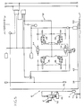
- an emergency air braking system 10 including a safety or interlock unit 12 is shown schematically in Fig. 5.
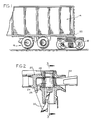
- the system 10 is constructed for use in a railway train, including a plurality of successive intermodal trailers 14, only one of which is shown in Fig. 1, which may be supported either by highway wheels 16 or a rail bogie 18.
- a rail bogie is disposed beneath a rear end of a trailer, and is constructed for lifting the trailer sufficiently to raise the wheels 16 above the ground.
- Each trailer 14 is provided with a socket 20, as indicated in Figs. 1 and 2, at its rear end for receiving a tongue 22 extending from the forward end of a succeeding trailer.
- a coupling pin 24 is mounted either on the bogie 18 or directly on and beneath the trailer.
- the coupling pin 24 is adapted to be shifted between a retracted position and an extended position, as shown in Fig. 2, in which the pin extends through an aperture 26 in the socket or fitting 20, and also an aperture 28 in the tongue 22 for coupling the trailers together.
- a suitable linkage 30 is connected with the coupling pin 24 for shifting the coupling pin between the extended position shown in Fig. 2 and a retracted position in which the coupling pin is fully withdrawn from the tongue 22 for decoupling the trailers.
- the braking system 10 may incorporate any well-known pneumatic circuitry, generally designated by the numeral 32 for actuating brake units 34 and 36 associated with the wheels of the bogie. Since such brake units and pneumatic systems are well-known, they need not be described in detail.
- a pneumatic brake line or brake pipe 38 also of known construction, extends through the trailer 14, and is provided with coupling means 40 at its opposite ends for enabling the pipe to be coupled to a pipe in an adjacent trailer, so as to form a continuous line from one end of a train to the other.
- relatively high air pressure is maintained in the brake pipe 38.
- the brake pipe is connected by a line 42 with the pneumatic system 32. The structure is such that when pressure is maintained in the brake pipe 38 and line 42, the brake units 34 and 36 are held in a deenergized position. In the event of a sudden drop in the line pressure, the brake units are actuated in a known manner.
- An interlock or safety unit 12 is provided for venting the brake pipe 38 whenever the coupling pin 24 is in a retracted position or disengaged from the tongue 22 of a trailer, so that the brake units 34 and 36 will be energized and the train cannot be moved.
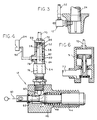
- the safety or interlock unit 12 includes a locking pin 44 slidably disposed in a fixed housing 46 mounted adjacent the coupling pin.
- a spring 48 is mounted within the housing for biasing the locking pin toward an extended position.
- the locking pin is adapted to snap beneath the coupling pin 24 when the coupling pin is in the extended trailer coupling position, as shown in Figs. 2 and 3, whereby positively to prevent reverse movement of the pin and decoupling of the trailers.
- a linkage mechanism 50 is connected with a rear end of the locking pin 44 and with a suitable actuator, not shown, whereby a trainman may withdraw the pin when it is desired to decouple the trailers.
- An air valve 52 including a body 54, is connected with the housing 46.
- a sliding valve element 56 is disposed within a central bore 58 in the valve body 54 and includes a stem 60 which extends into the housing 46 and engages with a reduced diameter portion 62 of the locking pin 44.
- the locking pin also includes a cam portion 64 disposed so that when the locking pin is retracted from the extended or locking position shown in Fig. 4, the cam portion 64 urges the valve stem 60 upwardly or outwardly against the action of a compression spring 66 disposed between a closed end 68 of the valve body 54 and the sliding valve element 56.
- An air line 70 is provided for connecting an inlet 72 in housing 54 with a signal part of an emergency brake valve or relay valve 71, which in turn is connected by pipe 73 to the brake pipe.
- the inlet 72 in turn, communicates with the central bore 58 in the housing.
- the valve body is formed with an outlet passageway 78 communicating with an annular channel 80 surrounding the valve element 56.
- an axially extending passageway 82 is formed in the valve element 56 from an upper end communicating with inlet 72 to a cross bore 84 for communicating with the channel 80. The arrangement is such then when the locking pin 44 is extended and the valve element 56 is in the position shown in Fig.
- the cross bore 84 is axially offset and disconnected from the annular channel 80, so that no air can flow through the valve.
- the cam surface 64 acting on the stem 60 shifts the valve element 56 sufficiently to connect the cross bore 84 with the channel 80 so that air may flow through the outlet 78.
- the air line 70 and the passageways through the valve 52 are relatively small, as compared with the diameter of the brake pipe 38, and connecting pipe 73 so that the air bleeding out through the outlet 78 when the valve 52 is opened is, by itself, usually insufficient to cause a pressure drop in the brake pipe which will actuate the emergency braking system of the train.
- the emergency brake valve or relay valve 71 is connected with the brake pipe 38 at 90, so that the bake pipe pressure will be quickly reduced when the valve 71 receives a pressure drop signal from the valve 52.
- the valve 71 may be of any known construction, such for example, as a valve sold by Knorr-Bremer.
- the structure of the valve 71, as shown in Fig. 6, is such that when the valve receives a pressure drop signal through the line 70, the valve will open, so as to vent the brake pipe 38 and, thereby, cause actuation of the emergency braking system.
- the brake units 34 and 36 will be energized whenever a coupling pin 24 is in a retracted or decoupling position. It is, of course, understood that a safety unit 12 will be provided for each trailer to be connected in a train. Thus, movement of the train will be prevented until all coupling pins have been properly positioned. Furthermore, in the event of some type of malfunction causing a coupling pin to be unintentionally retracted, the safety interlock unit will cause the emergency brake system of the train to be automatically energized without the need for any action on the part of a trainman.
- a branch line 92 is connected with the outlet 78 of the valve 52 and with a whistle 94 for providing an audible signal.
- the branch line 92 might also be connected with a mechanism, not shown, for extending some type of flag, which can be visually seen by a trainman.
Landscapes
- Engineering & Computer Science (AREA)
- Transportation (AREA)
- Mechanical Engineering (AREA)
- Regulating Braking Force (AREA)
- Braking Systems And Boosters (AREA)
- Valves And Accessory Devices For Braking Systems (AREA)
Claims (9)
- Système de freinage de secours pour un train, comportant un verrouillage de sécurité (12) entre un élément d'attelage de véhicules et un système de frein pneumatique (10) du train, caractérisé par un élément de verrouillage (44), pouvant être déplacé entre une position de retrait et une position d'extension, verrouillant l'élément d'attelage, une soupape à air (52), ladite soupape à air englobant un élément de soupape coulissant (60) réagissant audit élément de verrouillage (44) pour émettre un signal de pression d'air lorsque ledit élément de verrouillage se trouve dans l'une desdites positions et pour arrêter le signal lorsque l'élément de verrouillage se trouve dans l'autre desdites positions, ainsi qu'un moyen (71) régissant audit signal de pression d'air pour actionner le système de freinage du train lorsque l'élément de verrouillage est rétracté de ladite position d'attelage et de verrouillage.
- Système de freinage de secours selon la revendication 1, caractérisé en ce que ledit élément de verrouillage (24) englobe une surface à cames (64), ledit élément de soupape coulissant (60) pouvant s'engager dans ladite surface à cames.
- Système de freinage de secours selon la revendication 2, caractérisé par un moyen de ressort (48) pour pousser ledit élément de verrouillage (44) vers ladite position de verrouillage, et un moyen de liaison (50) pour rétracter ledit élément de verrouillage.
- Système de freinage de secours selon la revendication 1, caractérisé par un moyen (94) connecté à ladite soupape à air (52) et réagissant audit signal de pression d'air pour fournir un signal audible.
- Système de freinage de secours selon la revendication 1, caractérisé en ce que ledit moyen réagissant audit signal de pression d'air comprend une soupape-relais (71) pour purger une conduite de frein (38) du système de frein pneumatique.
- Système de freinage de secours selon la revendication 1, destiné à être utilisé avec un système de frein pneumatique d'un train comportant une conduite d'air (38), caractérisé en ce que ledit moyen réagissant au signal comprend une soupape (71) pour purger ladite conduite d'air.
- Système de freinage de secours selon la revendication 1, caractérisé par un moyen de signalisation (94) pour émettre un signal pouvant être discerné par un responsable du train en réponse audit signal de pression d'air.
- Système de freinage de secours selon la revendication 7, caractérisé en ce que ledit moyen de signalisation (44) émet un signal audible.
- Système de freinage de secours selon la revendication 1, pour un système de frein pneumatique comportant une conduite de frein (38) d'un train multimodal englobant plusieurs remorques attelées par des éléments d'attelage (24) pouvant se déplacer entre une position d'attelage et une position de désassemblage, caractérisé en ce que ledit verrouillage comprend une deuxième soupape (71), réagissant audit signal de pression d'air reçu de ladite première soupape (52) et pouvant être connectée à la conduite de frein (38) pour purger la conduite de frein en réponse audit signal et actionner ainsi le frein pneumatique.
Applications Claiming Priority (2)
| Application Number | Priority Date | Filing Date | Title |
|---|---|---|---|
| US07/897,290 US5297858A (en) | 1992-06-11 | 1992-06-11 | Safety coupler-air brake interlock |
| US897290 | 1992-06-11 |
Publications (2)
| Publication Number | Publication Date |
|---|---|
| EP0574130A1 EP0574130A1 (fr) | 1993-12-15 |
| EP0574130B1 true EP0574130B1 (fr) | 1995-10-04 |
Family
ID=25407692
Family Applications (1)
| Application Number | Title | Priority Date | Filing Date |
|---|---|---|---|
| EP93303494A Expired - Lifetime EP0574130B1 (fr) | 1992-06-11 | 1993-05-05 | Verrouillage de sûreté entre attelage et reinage à air comprimé |
Country Status (4)
| Country | Link |
|---|---|
| US (1) | US5297858A (fr) |
| EP (1) | EP0574130B1 (fr) |
| DE (1) | DE69300585T2 (fr) |
| ES (1) | ES2080591T3 (fr) |
Cited By (1)
| Publication number | Priority date | Publication date | Assignee | Title |
|---|---|---|---|---|
| US8215240B2 (en) | 2006-12-20 | 2012-07-10 | Railrunner N.A., Inc. | Bimodal container chassis |
Families Citing this family (7)
| Publication number | Priority date | Publication date | Assignee | Title |
|---|---|---|---|---|
| US5431110A (en) * | 1994-04-28 | 1995-07-11 | Adams, Jr.; George W. | Truck-train system with locking mechanism employing a moment arm |
| US5537931A (en) * | 1995-04-21 | 1996-07-23 | Wabash National Corporation | Bogie adapter for intermodal trailer |
| US5758890A (en) * | 1995-05-17 | 1998-06-02 | Rocky Mountain Technology & Engineering Corp | Locking system for a semitrailer chassis and removable container |
| US6652042B2 (en) * | 2002-01-17 | 2003-11-25 | James J. Johnson | Locking system for air brakes of parked trailer |
| US8857125B2 (en) | 2012-06-27 | 2014-10-14 | Industrial Hardwood Products, Inc. | Wood flooring with sealed joints for truck trailers and containers |
| US9434421B1 (en) | 2015-06-02 | 2016-09-06 | Rockland Flooring Llc | Wood flooring with reinforced thermoplastic underlayer |
| US11585069B2 (en) * | 2018-06-06 | 2023-02-21 | Caterpillar Inc. | Pin and retainer locking system |
Family Cites Families (6)
| Publication number | Priority date | Publication date | Assignee | Title |
|---|---|---|---|---|
| US284154A (en) * | 1883-08-28 | Relief-valve for railway pressure-brakes | ||
| US2963986A (en) * | 1956-10-25 | 1960-12-13 | Dominion Foundries & Steel | Combined highway and rail freight units |
| US3552325A (en) * | 1968-01-31 | 1971-01-05 | Gen Am Transport | Freight transportation system and components thereof |
| US4381713A (en) * | 1980-05-01 | 1983-05-03 | Bi-Modal Corporation | Convertible rail-highway semi-trailer air controlled braking and suspension shifting system |
| US4416571A (en) * | 1981-02-17 | 1983-11-22 | Krause Robert A | Truck and rail transportation system |
| US4792269A (en) * | 1985-09-16 | 1988-12-20 | General Signal Corporation | Container securing device |
-
1992
- 1992-06-11 US US07/897,290 patent/US5297858A/en not_active Expired - Fee Related
-
1993
- 1993-05-05 DE DE69300585T patent/DE69300585T2/de not_active Expired - Fee Related
- 1993-05-05 EP EP93303494A patent/EP0574130B1/fr not_active Expired - Lifetime
- 1993-05-05 ES ES93303494T patent/ES2080591T3/es not_active Expired - Lifetime
Cited By (2)
| Publication number | Priority date | Publication date | Assignee | Title |
|---|---|---|---|---|
| US8215240B2 (en) | 2006-12-20 | 2012-07-10 | Railrunner N.A., Inc. | Bimodal container chassis |
| US8677907B2 (en) | 2006-12-20 | 2014-03-25 | Railrunner, N.A., Inc. | Bimodal container chassis |
Also Published As
| Publication number | Publication date |
|---|---|
| ES2080591T3 (es) | 1996-02-01 |
| US5297858A (en) | 1994-03-29 |
| DE69300585D1 (de) | 1995-11-09 |
| DE69300585T2 (de) | 1996-03-14 |
| EP0574130A1 (fr) | 1993-12-15 |
Similar Documents
| Publication | Publication Date | Title |
|---|---|---|
| US9027949B2 (en) | Fifth wheel fluid lock safety system and method | |
| EP2318242B1 (fr) | Système de commande de freinage pour véhicule de remorquage et véhicule-remorque associés | |
| US5383717A (en) | Brake control of helper locomotive | |
| US6685281B2 (en) | Parking brake control system | |
| US7971942B2 (en) | Trailer brake system | |
| US4641846A (en) | Interlock system for a trailer and bogie | |
| CN113562021B (zh) | 一种联挂救援停放制动状态指示电路 | |
| US20180170459A1 (en) | Vehicle coupling lines storage and control arrangement | |
| US5297858A (en) | Safety coupler-air brake interlock | |
| EP2223831B1 (fr) | Système de freinage pour marche arrière | |
| EP3436290A1 (fr) | Agencement de stockage et de commande de lignes de couplage de véhicule | |
| GB2171476A (en) | Spring-loaded parking-brake and service-brake system for trailers | |
| SE445821B (sv) | Bromssystem for slepfordon | |
| GB1572439A (en) | Trailer braking systems | |
| US5683148A (en) | Brake pipe pneumatic valve | |
| US1891660A (en) | Car coupling mechanism | |
| US5392876A (en) | Anti-theft method and device for automotive vehicles | |
| US5211698A (en) | Railroad train braking system with a continuously venting coupler | |
| BRPI0609913B1 (pt) | Trem incluindo um tubo de freio automático e uma linha de alimentação elétrica | |
| US5180213A (en) | Brake pipe continuity valve system | |
| US7562781B2 (en) | Automatic cut lever apparatus | |
| WO2003020561A1 (fr) | Systeme de verrouillage de securite de plaque tournante | |
| US2163519A (en) | Automatic emergency train line air control | |
| EP0739798A2 (fr) | Dispositif de sécurité applicable au système de freinage pneumatique de stationnement de véhicules | |
| WO2025195754A1 (fr) | Agencement de soupape de libération de stationnement, agencement de frein, remorque complète |
Legal Events
| Date | Code | Title | Description |
|---|---|---|---|
| PUAI | Public reference made under article 153(3) epc to a published international application that has entered the european phase |
Free format text: ORIGINAL CODE: 0009012 |
|
| AK | Designated contracting states |
Kind code of ref document: A1 Designated state(s): DE ES FR GB IT |
|
| 17P | Request for examination filed |
Effective date: 19931222 |
|
| 17Q | First examination report despatched |
Effective date: 19941215 |
|
| GRAA | (expected) grant |
Free format text: ORIGINAL CODE: 0009210 |
|
| AK | Designated contracting states |
Kind code of ref document: B1 Designated state(s): DE ES FR GB IT |
|
| ITF | It: translation for a ep patent filed | ||
| REF | Corresponds to: |
Ref document number: 69300585 Country of ref document: DE Date of ref document: 19951109 |
|
| ET | Fr: translation filed | ||
| REG | Reference to a national code |
Ref country code: ES Ref legal event code: FG2A Ref document number: 2080591 Country of ref document: ES Kind code of ref document: T3 |
|
| PLBE | No opposition filed within time limit |
Free format text: ORIGINAL CODE: 0009261 |
|
| STAA | Information on the status of an ep patent application or granted ep patent |
Free format text: STATUS: NO OPPOSITION FILED WITHIN TIME LIMIT |
|
| 26N | No opposition filed | ||
| REG | Reference to a national code |
Ref country code: GB Ref legal event code: IF02 |
|
| PGFP | Annual fee paid to national office [announced via postgrant information from national office to epo] |
Ref country code: FR Payment date: 20040510 Year of fee payment: 12 |
|
| PGFP | Annual fee paid to national office [announced via postgrant information from national office to epo] |
Ref country code: GB Payment date: 20040512 Year of fee payment: 12 |
|
| PGFP | Annual fee paid to national office [announced via postgrant information from national office to epo] |
Ref country code: DE Payment date: 20040513 Year of fee payment: 12 |
|
| PGFP | Annual fee paid to national office [announced via postgrant information from national office to epo] |
Ref country code: ES Payment date: 20040519 Year of fee payment: 12 |
|
| PG25 | Lapsed in a contracting state [announced via postgrant information from national office to epo] |
Ref country code: IT Free format text: LAPSE BECAUSE OF NON-PAYMENT OF DUE FEES Effective date: 20050505 Ref country code: GB Free format text: LAPSE BECAUSE OF NON-PAYMENT OF DUE FEES Effective date: 20050505 |
|
| PG25 | Lapsed in a contracting state [announced via postgrant information from national office to epo] |
Ref country code: ES Free format text: LAPSE BECAUSE OF NON-PAYMENT OF DUE FEES Effective date: 20050506 |
|
| PG25 | Lapsed in a contracting state [announced via postgrant information from national office to epo] |
Ref country code: DE Free format text: LAPSE BECAUSE OF NON-PAYMENT OF DUE FEES Effective date: 20051201 |
|
| GBPC | Gb: european patent ceased through non-payment of renewal fee |
Effective date: 20050505 |
|
| PG25 | Lapsed in a contracting state [announced via postgrant information from national office to epo] |
Ref country code: FR Free format text: LAPSE BECAUSE OF NON-PAYMENT OF DUE FEES Effective date: 20060131 |
|
| REG | Reference to a national code |
Ref country code: FR Ref legal event code: ST Effective date: 20060131 |
|
| REG | Reference to a national code |
Ref country code: ES Ref legal event code: FD2A Effective date: 20050506 |