EP0574192A2 - Architektur zur Ausführung der hierarchischen Bewegungsanalyse von Bildern in Echtzeit - Google Patents
Architektur zur Ausführung der hierarchischen Bewegungsanalyse von Bildern in Echtzeit Download PDFInfo
- Publication number
- EP0574192A2 EP0574192A2 EP93304347A EP93304347A EP0574192A2 EP 0574192 A2 EP0574192 A2 EP 0574192A2 EP 93304347 A EP93304347 A EP 93304347A EP 93304347 A EP93304347 A EP 93304347A EP 0574192 A2 EP0574192 A2 EP 0574192A2
- Authority
- EP
- European Patent Office
- Prior art keywords
- image
- pixel
- motion
- vector
- density
- Prior art date
- Legal status (The legal status is an assumption and is not a legal conclusion. Google has not performed a legal analysis and makes no representation as to the accuracy of the status listed.)
- Granted
Links
Images


Classifications
-
- H—ELECTRICITY
- H04—ELECTRIC COMMUNICATION TECHNIQUE
- H04N—PICTORIAL COMMUNICATION, e.g. TELEVISION
- H04N5/00—Details of television systems
- H04N5/14—Picture signal circuitry for video frequency region
- H04N5/144—Movement detection
- H04N5/145—Movement estimation
-
- H—ELECTRICITY
- H04—ELECTRIC COMMUNICATION TECHNIQUE
- H04N—PICTORIAL COMMUNICATION, e.g. TELEVISION
- H04N9/00—Details of colour television systems
- H04N9/77—Circuits for processing the brightness signal and the chrominance signal relative to each other, e.g. adjusting the phase of the brightness signal relative to the colour signal, correcting differential gain or differential phase
-
- G—PHYSICS
- G06—COMPUTING OR CALCULATING; COUNTING
- G06T—IMAGE DATA PROCESSING OR GENERATION, IN GENERAL
- G06T7/00—Image analysis
- G06T7/20—Analysis of motion
- G06T7/207—Analysis of motion for motion estimation over a hierarchy of resolutions
-
- H—ELECTRICITY
- H04—ELECTRIC COMMUNICATION TECHNIQUE
- H04N—PICTORIAL COMMUNICATION, e.g. TELEVISION
- H04N19/00—Methods or arrangements for coding, decoding, compressing or decompressing digital video signals
- H04N19/50—Methods or arrangements for coding, decoding, compressing or decompressing digital video signals using predictive coding
- H04N19/503—Methods or arrangements for coding, decoding, compressing or decompressing digital video signals using predictive coding involving temporal prediction
- H04N19/51—Motion estimation or motion compensation
- H04N19/53—Multi-resolution motion estimation; Hierarchical motion estimation
-
- H—ELECTRICITY
- H04—ELECTRIC COMMUNICATION TECHNIQUE
- H04N—PICTORIAL COMMUNICATION, e.g. TELEVISION
- H04N19/00—Methods or arrangements for coding, decoding, compressing or decompressing digital video signals
- H04N19/50—Methods or arrangements for coding, decoding, compressing or decompressing digital video signals using predictive coding
- H04N19/503—Methods or arrangements for coding, decoding, compressing or decompressing digital video signals using predictive coding involving temporal prediction
- H04N19/51—Motion estimation or motion compensation
- H04N19/537—Motion estimation other than block-based
Definitions
- HMA hierarchical motion analysis
- the maximum expected motion for the analysis at each level is 1 ( ⁇ 1 pixel), while the total maximum motion can be 2 n , where n+1 is the number of resolution levels of the multiresolution representation.
- the total required computational operations at all resolution levels, regardless of the number of resolution levels, is now reduced to no more than 4/3*C*(N2*K).
- HMA HMA
- the present invention is directed to hardware architecture for the practical implementation of HMA in real time, thereby making HMA cost effective for studio type applications employing digital television equipment.
- Applications for such digital television equipment include frame rate conversion, scan conversion, noise cleaning, and image compression.
- the present invention relates to an image-processing system comprising first and second hardware means, which system, in response to relatively high-resolution image data from an ongoing input series of successive given pixel-density image-data frames that occur at a given frame rate, derives, after a certain processing-system delay, an ongoing output series of successive given pixel-density vector-data frames that occur at the same given frame rate.
- Each vector-data frame is indicative of image motion occurring between each pair of successive image frames.
- the first hardware means is used to represent the image data of each single one of the image-frames at n+1 ordinally-arranged successively lower pixel-density levels 0....n within a first time interval equal in length to a given fraction of the certain processing-system delay, where n is a given integer having a value of at least 1.
- the pixel-density of level 0 corresponds to the given pixel density and the pixel-density of level n corresponds to a lowest pixel density.
- the maximum expected image motion occurring between two successive frames is typically no greater than one pixel distance at the lowest pixel-density.
- the second hardware means which incorporates at least one image buffer means, at least one warp means, at least one motion-analysis means, at least one pixel-density expand means, and at least one adder means, sequentially employs the image data at the pixel-density levels n....0 to derive, within a second time interval equal in length to a remaining fraction of the certain processing-system delay, a separate motion vector for each pixel at each of the pixel-density levels, starting with the lowest pixel-density n, for that pair of successive image-frames.
- a high-resolution motion-vector map at the given pixel-density may be derived in real time in response to each pair of successive given pixel-density image-frames of the ongoing input series.
- the present invention is concerned with the "real-time" processing of an ongoing series of successive image-data frames that are applied as an input to an image-processing system for deriving as an output an ongoing series of successive vector-data frames. Since it inherently takes time to process image data, there will always be a delay between the processed data output from the system and the data input to the system. As used herein, the term "real-time” means that the successive output frames emerge from the image-processing system at the same rate that the successive input frames are applied thereto, as illustrated in FIGURE 1, despite the existence of a processing system delay between the occurrence of corresponding output and input frames.
- a given set of four consecutive frame periods 1, 2, 3 and 4 of an ongoing input series of image-data frame periods applied to an image processing system at a given rate emerges, after a certain system processing delay, as a corresponding set of four consecutive frame periods 1, 2, 3 and 4 of an ongoing output series of vector-data frame periods that occurs at the same given rate. Therefore, while the system processing delay may be longer than a frame period (as shown in FIGURE 1) or shorter, the length of each frame period of the ongoing output series of vector-data frame periods is equal to the length of each frame period of the ongoing input series of image-data frame periods.
- the output from image data means 200 comprises, in digital form, an ongoing stream of image-data pixels of each of successive 2-dimensional video frames.
- the relatively high pixel density of the Gaussian output G0 of each successive video frame of the image-data output from means 200 occurs at a clock CL0 having a frequency f c .
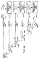
- the output G0 is applied (1) directly through delay means 202a to image means 204 and (2) in cascade through each of Laplacian image-pyramid stages 206a-1....206a-5.
- Laplacian image-pyramid For a detailed description of a Laplacian image-pyramid, reference should be made to U.S. patent 4,674,125, which issued to Carlson et al. on June 16, 1987.
- the structure of a Laplacian image-pyramid stage 206-k operating with a clock CL k having a frequency equal to 1/4 k-1 f c , comprises 2-dimensional convolution filter/decimator 208, expander/interpolation filter 210, subtractor 212 and delay means 214.
- Convolution filter/decimator 208 which may include a rate buffer for deriving equispaced output pixels, reduces both the horizontal image pixel density and the vertical image pixel density by one-half, so that the pixel image density of a Gaussian image output G k from stage 206-k is only one-quarter of the image pixel density of the Gaussian input G k-1 thereto.
- a Laplacian image output L k-1 from stage 206-k (having the image pixel density of G k-1 ) is derived by subtracting each image pixel output from expander/interpolation filter 210 from the corresponding image pixel input G k-1 , after delay by delay means 214.
- the image pixel density of G4 and of L4 is only 1/256 of the high image pixel density G0 of the original image data (i.e., each of the horizontal and vertical image distances covered by each lowest-density G4 pixel or L4 pixel is 8 times larger than the horizontal and vertical image distances covered by each highest-density G0 pixel).
- the maximum image motion that can occur between two successive image frames is no greater than one lowest-density image pixel distance in the horizontal direction or in the vertical direction.
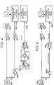
- the respective Laplacian image outputs L0 aloneL3 from stages 206a- 1 whil206a-4, after suitable delays by delay means 202a-1 etca-4, are applied respectively to motion-vector stages 216-1 Vietnamese-4, while the Laplacian image output L4 from stage 206a-5, with no delay, is applied to motion-vector stage 216-5.
- Motion-vector stage 216-5 may be implemented as shown in FIGURE 2d, while each of motion-vector stages 216-1 alone216-4 may be implemented as shown in FIGURE 2e or, alternatively, FIGURE 2f.
- the respective outputs of motion-vector stages 216-5 «216-2 are cascaded upward to motion-vector stage 216-1 and the motion-vector output from motion-vector stage 216-1 is applied to V x,y means 218.
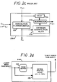
- the lowest image pixel density i.e., the Laplacian image output L4 from stage 206a-5 in the case of FIGURE 2a
- the output from image buffer 222 is applied as a second input to motion analysis means 220.
- Image buffer 222 stores the values of all of the L4 pixels of the preceding image frame for one frame period and then forwards these pixels to motion analysis means 220 concurrently with the application thereto of the corresponding pixels of the current image frame.
- Motion analysis means 220 which makes an independent best estimate of pixel motion V x and V y of each individual pixel in the horizontal (X) and in the vertical (Y) directions and are typically in the range between ⁇ 1 pixel distance in the X and Y directions, makes use of known correlation, least-square best-fit or other techniques.
- FIGURE 3 shows one known example of the computations required to implement motion analysis means 220 using least-square best-fit techniques.
- Motion-vector stage 216-4, as well as each of motion-vector stages 216-3, 216-2 and 216-1, may be implemented either in the manner shown in FIGURE 2e or in FIGURE 2f.
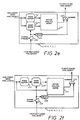
- the structure of FIGURE 2e like the structure of FIGURE 2d, includes motion analysis means 220 and image buffer 222, and, in addition, includes warp means 224e, expand-pyramid means 226, delay means 228 and summer 230. Except for replacing warp means 224e with warp means 224f, the structure of FIGURE 2f is the same as that of the structure of FIGURE 2e.
- the non-lowest image pixel density (i.e., the Laplacian image output L3, L2, L1 or L0 from stage 206a-4, 206a-3, 206a-2, 206a-1 or 206a-0, respectively, in the case of FIGURE 2a) is applied as a signal input to both warp means 224e and image buffer 222, and the respective outputs from warp means 224e and image buffer 222 are applied as first and second inputs to motion analysis means 220.
- the output from motion analysis means 220 is applied as a first input to summer 230.
- V x and V y motion vector outputs derived by the next-lower pixel density motion-vector stage 216-5, 216-4, 216-3 or 216-2, respectively, is applied as an input to expand-pyramid means 226 of motion-vector stage 216-4, 216-3, 216-2 or 216-1, respectively.
- Expand-pyramid means 226 is effective in doubling the pixel density of each of the V x and each of the V y motion vectors, while at the same time doubling the value of each of these motion vectors (since a single pixel distance at the next-lower pixel density of each of the V x and each of the V y motion vectors is equal to 2 pixel distances at the expanded pixel density of each of the V x and each of the V y motion vectors).
- the expanded V x and V y motion vectors at the output of expand-pyramid means 226 are applied as a control input to warp means 224e and through delay means 228 as a second input to summer 230.
- Warp means 224e is effective in displacing backward each individual image pixel of the current image frame applied thereto toward the corresponding image pixel of the stored preceding image frame, then at the output of image buffer 222, by its corresponding V x image-pixel distance in the horizontal direction and by its corresponding V y image-pixel distance in the vertical direction. Therefore, the motion analysis means 220 of FIGURE 2e need only make a best estimate of residual motion that has taken place of each corresponding image pixel between the current image frame and the preceding image frame.
- the delay provided by delay means 228 ensures that the residual V x and V y motion vectors of each pixel applied to the first input of summer 230 occur concurrently with the expanded V x and V y motion vectors of each corresponding pixel derived from the next-lower pixel density motion-vector stage 216-5, 216-4, 216-3 or 216-2, respectively.
- V x and V y motion vectors for each pixel at the output of summer 230 of each subsequent higher pixel density one of motion-vector stages 216-4, 216-3 216-2 and 216-1 define the V x and V y motion vectors of each pixel with greater and greater precision, so that the 2-dimensional estimate of the motion vector for each pixel at the output of summer 230 of highest-pixel density motion-vector stage 216-1, which is applied to V x,y means 218, is 256 times more precise than the 2-dimensional estimate of the motion vector for each pixel at the output of summer 230 of lowest-pixel density motion-vector stage 216-5.
- the non-lowest image pixel density (i.e., the Laplacian image output L3, L2, L1 or L0 from stage 206a-4, 206a-3, 206a-2, 206a-1 or 206a-0, respectively, in the case of FIGURE 2a) is applied directly as a first input to motion analysis means 220 and as an input to image buffer 222, with the output from image buffer 222 being applied as a signal input to warp means 224f, and the output from warp means 224f being applied as a second input to motion analysis means 220.
- the non-lowest image pixel density i.e., the Laplacian image output L3, L2, L1 or L0 from stage 206a-4, 206a-3, 206a-2, 206a-1 or 206a-0, respectively, in the case of FIGURE 2a
- Warp means 224f is effective in displacing forward each individual image pixel, applied thereto, of the stored preceding image frame then at the output of image buffer 222, toward the corresponding image pixel of the current image frame by its corresponding V x image-pixel distances in the horizontal direction and by its corresponding V y image-pixel distances in the vertical direction.
- FIGURE 2f is identical in structure and function to that of above-described FIGURE 2e.
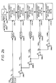
- each of Gaussian image-pyramid stages 206b-2....206b-5 comprises solely 2-dimensional convolution filter/decimator 208c, with the respective G 1 Vietnamese G4 outputs of Gaussian image-pyramid stages 206b-1....206b-4 of FIGURE 2b replacing the respective L1 VietnameseL4 outputs of Laplacian image-pyramid stages 206a-1....206a-4 of FIGURE 2a.
- the Gaussian image-pyramid of FIGURE 2b and the Laplacian image-pyramid of FIGURE 2a are, for the most part, equivalent.
- the Laplacian image-pyramid of FIGURE 2a is to be preferred
- each of the respective delay means 202 of FIGURE 2a or FIGURE 2b is set to compensate for these inherent system processing delays and thereby ensure timing concurrence in all cases between interacting corresponding image and motion-vector pixels that have traveled to each of the motion-vector stages over different paths.
- the minimum total system processing delay of the Gaussian FIGURE 2b embodiment of the present invention is slightly less than that of the Laplacian FIGURE 2a embodiment of the present invention. Specifically, with an NTSC scan-line period of 63.5 ⁇ s (including blanking time), the minimum realizable total system processing delay of the Gaussian FIGURE 2b embodiment (with G4 being the lowest pixel density) is 144.3 scan-line periods, while the minimum realizable total system processing delay of the Laplacian FIGURE 2a embodiment is increased by 35 scan-line periods to 178.3 scan-line periods.
- the delay in scan-line periods provided by each of delay means 202b-1 ...202b-4 is determined by the differential system processing delay between its two end points, divided by the reduction in the clock frequency f c at that pyramid level. For instance, the delay provided by delay means 202b-2 is 132.23/4 scan-line periods.
- each of the FIGURE 2a and FIGURE 2b embodiments requires a large amount of hardware to implement.
- each of the FIGURE 2a and FIGURE 2b embodiments requires five separate motion-vector stages, each of which includes its own rather complex and costly motion analysis means in order to achieve a relatively small minimum realizable total system processing delay for only five pyramid levels.
- the FIGURE 4 embodiment employs a Laplacian image pyramid, but could, if desired, employ a Gaussian image pyramid instead.
- image data means 400, delay means 402, image data means 404, Laplacian image pyramid stage 406-1, delay means 402-1, motion-vector stage 416-1 and V x,y means 418 of FIGURE 4 are identical in structure and function to image data means 200, delay means 202a, image data means 204, Laplacian image pyramid stage 206a-1, delay means 402a-1, motion-vector stage 216-1 and V x,y means 218 of FIGURE 2a.
- the G1 output of Laplacian image pyramid stage 406-1 is applied as a first input to functionally 3-port frame buffer 432.
- the output from frame buffer 432 is applied as an input to Laplacian image pyramid stage 406-n (comprising structure shown in FIGURE 2c), with the Laplacian output therefrom being applied as an input to frame buffer 434 and the Gaussian output therefrom being fed back as a second input to frame buffer 432.
- the output from frame buffer 434 is applied as an input to feedback motion-vector stage 416-n, which may be implemented as shown in FIGURE 4a discussed below.
- Motion-vector stage 416-n derives as an output V x and V y motion vectors at the G1 pixel-density level, which are applied as a warp-control input to motion-vector stage 416-1.
- frame buffer 432 may comprise a single 3-port frame memory having two independent input ports and a single output port, or, alternatively, may comprise either two 2-port frame memories capable of having one of their two output ports selected by a switch, as shown in FIGURE 4b, or four 1-port frame memories each having its one port either unselected or selected as an input or as an output port by a group of switches, as shown in FIGURE 4c.
- the readout from frame buffer 432 of the stored G1 pixels of each video frame results in stage 406n deriving a Laplacian output L1 and a Gaussian output G2.
- the Gaussian output G2 which is fed back as an input to frame buffer 432, stored therein and then read out therefrom as an input to stage 406n, results in stage 406n deriving a Laplacian output L2 and a Gaussian output G3. This recycling process continues until stage 406n derives a Laplacian output L n and a Gaussian output G n+1 (where n may have as high an integral value as desired), which Gaussian output G n+1 is not recycled through frame buffer 432.
- feedback motion-vector stage 416-n may comprise motion analysis means 420, image buffer 422 and warp means 424e (which are interconnected in a manner similar to that shown in FIGURE 2e and are responsive to each of the L n.... L2 output from frame buffer 434 being applied in sequential order as an input to feedback motion-vector stage 416-n).
- Feedback motion-vector stage 416-n may also comprise expand-pyramid stage 426, delay means 428, summer 430 and dual-port frame buffer 436.
- the output from motion analysis means 420 is applied as a first input to summer 430 and the output from summer 430 is applied as an input to frame buffer 436.
- the output from frame buffer 436 is fed back through expand-pyramid stage 426 and applied both as a warp control input to warp means 424e and through delay means 428 as a second input to summer 430 in response to each of the L n....
- warp means connected as is warp means 224f in FIGURE 2f, can be substituted in FIGURE 4a for warp means 424e.
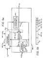
- FIGURE 5 embodiment of the present invention requires only a single motion-vector stage, regardless of how many pyramid levels are involved. Further, the FIGURE 5 embodiment need not insert additional system processing delay, as is the case in the FIGURE 4 embodiment. This is accomplished by employing a single image pyramid stage 506-n, having the structure shown in FIGURE 5a discussed below, to derive, at an increased clock frequency and in a novel scan-line order, each of Laplacian outputs L0 aloneL n applied as an input to frame buffer 534.
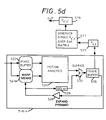
- Frame buffer 534 may then apply at this increased clock frequency each of its Laplacian outputs L0 thoughL n in a different predetermined order as an input to feedback motion-vector stage 516-n.(having the structure shown in FIGURE 5d), and the output from feedback motion-vector stage 516-n is applied directly to V x,y means 518.
- image pyramid stage 506-n comprises convolution filter/decimator 508, expander/interpolation filter 510 and subtractor 512 (which correspond to convolution filter/decimator 208, expander/interpolation filter 210 and subtractor 212,of FIGURE 2c), and partitioned line buffer means 540.
- a stream of Gaussian G0 image data pixels, occurring at the CL0 input clock frequency, is applied as an input to partitioned line buffer means 540, while the operating rate of the output from partitioned line buffer means 540 and of convolution filter/decimator 508, expander/interpolation filter 510 and subtractor 512 is at an increased clock frequency of 1.5 CL0.
- partitioned line buffer means 540 includes n+1 storage bins for separately storing each of G0....G n pixels (e.g., G0, G1, G2 and G3). Each of these stored G0....G n pixels (i.e., G 0:n ) may be read out and applied as an input to convolution filter/decimator 208, which derives each of G 1:(n+1) pixels.
- Each of G (n+1) pixels are applied as an input to expander/interpolation filter 510, with the output EXP G 1:(n+1) (having the same respective pixel densities as G 0:n ) from expander/interpolation filter 510 being separately stored in n+1 additional bins of partitioned line buffer means 540 (as shown in FIGURE 5b).
- Subtractor 512 subtracts the values of EXP G 1:n pixels read out (in the order shown in FIGURE 5c) from partitioned line buffer means 540 from corresponding G 0:n pixels also read out (in the order shown in FIGURE 5c) from partitioned line buffer means 540, thereby deriving (in the order shown in FIGURE 5c) the L 0:n Laplacian output from image pyramid stage 506-n that is applied as an input to frame buffer 534.
- the structure of feedback motion-vector stage 516-n is the same as the structure of feedback motion-vector stage 416-n, shown in FIGURE 4a.
- the order of the Laplacian output from frame buffer 534 applied as an input to FIGURE 5d may be different from that of the input to FIGURE 4a. More specifically, the Laplacian stored data from feedback motion-vector stage 416-n is applied to frame buffer 534, at the increased rate of 1.5 CL0, either in a time sequential manner or, alternatively, in a time multiplexed manner.
- FIGURE 5d structure of feedback motion-vector stage 416-n to obtain the V x,y motion vectors at the highest pixel density of L0 is performed in a manner similar to that of the FIGURE 4a embodiment, resulting in an additional system processing delay of (1) 1/3 divided by 1.5 of a video frame period (where 1.5 corresponds to the increase in clock frequency) before the V x,y motion vectors at the highest pixel density of L0 can be computed, plus (2) 1/1.5 of a video frame period for the highest pixel density of L0.
- the FIGURE 5d structural arrangement is modified to include a partitioned line buffer means similar to that shown in FIGURE 5a instead of delay means 528. While the control of data flow and warp means is now more complex, the total system processing delay can be made similar to that of the FIGURE 2a embodiment. Specifically, while the cumulative processing time of the sum of all n pixel-density levels taken together may exceed a video frame period, the processing time of each individual pixel-density level (including the longest L0 pixel-density level) employing the 1.5 CL0 clock frequency is substantially smaller than a video frame period. Therefore, the processing of consecutive pixel-density levels can be overlapping in processing time.
- L n of a first-occurring video frame is still being processed
- L0 of a second-occurring video frame can already start its processing, and while the highest-pixel-density motion-vector values of a first-occurring video frame are still being computed, all of the lower-pixel-density motion-vector values of a second-occurring video frame may already have been computed.
- the pyramid stage 506-n of the filter/decimate-expand filter type may be replaced with a pyramid stage of the filter-subtract-decimate type to realize a more parts efficient embodiment. See U.S. Patent 4,674,125 for an example of a filter-subtract-decimate module.
- the described HMA implementations generate (typically) a motion vector for every pixel in the image. These are obtained by first computing motion vectors for a low resolution representation of the image (level n), where each vector V n has a subpixel resolution (relative to that image resolution) and represents a motion of V n *2n at the highest (full image resolution (level 0). These motion vectors V n are then refined at the next higher resolution level n-1, obtaining a (subpixel) motion vector V n-1 for each pixel at resolution level n-1. This process is typically repeated until the motion vectors V o are computed at highest resolution (level 0).
- Final motion vector representation does not have to be at full resolution, but may be at a lower resolution.
- This motion vector can be obtained through HMA methods (implementations) by either
Landscapes
- Engineering & Computer Science (AREA)
- Multimedia (AREA)
- Signal Processing (AREA)
- Computer Vision & Pattern Recognition (AREA)
- Physics & Mathematics (AREA)
- General Physics & Mathematics (AREA)
- Theoretical Computer Science (AREA)
- Image Analysis (AREA)
- Television Systems (AREA)
- Compression Or Coding Systems Of Tv Signals (AREA)
- Memory System Of A Hierarchy Structure (AREA)
- Information Retrieval, Db Structures And Fs Structures Therefor (AREA)
Applications Claiming Priority (2)
| Application Number | Priority Date | Filing Date | Title |
|---|---|---|---|
| US896771 | 1986-08-15 | ||
| US07/896,771 US5276513A (en) | 1992-06-10 | 1992-06-10 | Implementation architecture for performing hierarchical motion analysis of video images in real time |
Publications (3)
| Publication Number | Publication Date |
|---|---|
| EP0574192A2 true EP0574192A2 (de) | 1993-12-15 |
| EP0574192A3 EP0574192A3 (de) | 1995-05-24 |
| EP0574192B1 EP0574192B1 (de) | 2002-10-02 |
Family
ID=25406802
Family Applications (1)
| Application Number | Title | Priority Date | Filing Date |
|---|---|---|---|
| EP93304347A Expired - Lifetime EP0574192B1 (de) | 1992-06-10 | 1993-06-04 | Architektur zur Ausführung der hierarchischen Bewegungsanalyse von Bildern in Echtzeit |
Country Status (7)
| Country | Link |
|---|---|
| US (1) | US5276513A (de) |
| EP (1) | EP0574192B1 (de) |
| JP (1) | JP3354636B2 (de) |
| KR (1) | KR100303097B1 (de) |
| DE (1) | DE69332348T2 (de) |
| MX (1) | MX9303450A (de) |
| SG (1) | SG75760A1 (de) |
Cited By (3)
| Publication number | Priority date | Publication date | Assignee | Title |
|---|---|---|---|---|
| EP0778698A3 (de) * | 1995-12-06 | 1997-07-16 | Thomson Multimedia Sa | |
| EP0710032A3 (de) * | 1994-10-28 | 1998-04-15 | Vistek Electronics Limited | Verfahren und Vorrichtung zur Bewegungsschätzung in einem Bildsignal |
| EP0929192A3 (de) * | 1998-01-07 | 1999-08-04 | Sony Corporation | Verfahren und Vorrichtung zum Verarbeiten von Bildern und Aufnahmemedium dafür |
Families Citing this family (49)
| Publication number | Priority date | Publication date | Assignee | Title |
|---|---|---|---|---|
| GB9405914D0 (en) | 1994-03-24 | 1994-05-11 | Discovision Ass | Video decompression |
| US6067417A (en) | 1992-06-30 | 2000-05-23 | Discovision Associates | Picture start token |
| US6112017A (en) | 1992-06-30 | 2000-08-29 | Discovision Associates | Pipeline processing machine having a plurality of reconfigurable processing stages interconnected by a two-wire interface bus |
| US5784631A (en) | 1992-06-30 | 1998-07-21 | Discovision Associates | Huffman decoder |
| US6079009A (en) | 1992-06-30 | 2000-06-20 | Discovision Associates | Coding standard token in a system compromising a plurality of pipeline stages |
| US5821885A (en) | 1994-07-29 | 1998-10-13 | Discovision Associates | Video decompression |
| US7095783B1 (en) | 1992-06-30 | 2006-08-22 | Discovision Associates | Multistandard video decoder and decompression system for processing encoded bit streams including start codes and methods relating thereto |
| US6263422B1 (en) | 1992-06-30 | 2001-07-17 | Discovision Associates | Pipeline processing machine with interactive stages operable in response to tokens and system and methods relating thereto |
| US5768561A (en) | 1992-06-30 | 1998-06-16 | Discovision Associates | Tokens-based adaptive video processing arrangement |
| DE69229338T2 (de) | 1992-06-30 | 1999-12-16 | Discovision Associates, Irvine | Datenpipelinesystem |
| US6330665B1 (en) | 1992-06-30 | 2001-12-11 | Discovision Associates | Video parser |
| US5809270A (en) | 1992-06-30 | 1998-09-15 | Discovision Associates | Inverse quantizer |
| US6047112A (en) | 1992-06-30 | 2000-04-04 | Discovision Associates | Technique for initiating processing of a data stream of encoded video information |
| DE4322343C2 (de) * | 1992-07-06 | 1996-10-02 | Mitsubishi Electric Corp | Mittel zum Erfassen eines Bewegungsvektors und Verfahren zum Bestimmen eines Bewegungsvektors |
| KR0166724B1 (ko) * | 1993-05-08 | 1999-03-20 | 김광호 | 반화소정확도를 갖는 동벡터추정방법 및 그 장치 |
| US5699544A (en) * | 1993-06-24 | 1997-12-16 | Discovision Associates | Method and apparatus for using a fixed width word for addressing variable width data |
| US5861894A (en) | 1993-06-24 | 1999-01-19 | Discovision Associates | Buffer manager |
| US5805914A (en) | 1993-06-24 | 1998-09-08 | Discovision Associates | Data pipeline system and data encoding method |
| US5477272A (en) * | 1993-07-22 | 1995-12-19 | Gte Laboratories Incorporated | Variable-block size multi-resolution motion estimation scheme for pyramid coding |
| US6005983A (en) * | 1993-09-08 | 1999-12-21 | California Institutue Of Technology | Image enhancement by non-linear extrapolation in frequency space |
| DE4342305A1 (de) * | 1993-12-11 | 1995-06-29 | Thomson Brandt Gmbh | Verfahren zur hierarchischen Bewegungsschätzung in einem Fernsehsignal |
| TW321748B (de) * | 1994-02-23 | 1997-12-01 | Rca Thomson Licensing Corp | |
| CA2145379C (en) | 1994-03-24 | 1999-06-08 | William P. Robbins | Method and apparatus for addressing memory |
| CA2145365C (en) | 1994-03-24 | 1999-04-27 | Anthony M. Jones | Method for accessing banks of dram |
| CA2145361C (en) | 1994-03-24 | 1999-09-07 | Martin William Sotheran | Buffer manager |
| GB9417138D0 (en) | 1994-08-23 | 1994-10-12 | Discovision Ass | Data rate conversion |
| US5598352A (en) * | 1994-09-30 | 1997-01-28 | Cirrus Logic, Inc. | Method and apparatus for audio and video synchronizing in MPEG playback systems |
| US5815634A (en) * | 1994-09-30 | 1998-09-29 | Cirrus Logic, Inc. | Stream synchronization method and apparatus for MPEG playback system |
| KR0178231B1 (ko) * | 1995-08-10 | 1999-05-01 | 배순훈 | 계층적인 움직임 추정 기법을 이용하는 움직임 벡터 검출 방법 및 장치 |
| KR0182058B1 (ko) * | 1995-05-10 | 1999-05-01 | 김광호 | 움직임 추정을 위한 다중 해상도 순환 탐색 장치 및 그 방법 |
| JP2798120B2 (ja) * | 1995-08-04 | 1998-09-17 | 日本電気株式会社 | 動き補償フレーム間予測方法及び動き補償フレーム間予測装置 |
| WO1997016926A1 (en) * | 1995-10-31 | 1997-05-09 | Sarnoff Corporation | Method and apparatus for determining ambient conditions from an image sequence |
| US5764283A (en) * | 1995-12-29 | 1998-06-09 | Lucent Technologies Inc. | Method and apparatus for tracking moving objects in real time using contours of the objects and feature paths |
| JPH09212650A (ja) * | 1996-02-05 | 1997-08-15 | Sony Corp | 動きベクトル検出装置および検出方法 |
| US5838377A (en) * | 1996-12-20 | 1998-11-17 | Analog Devices, Inc. | Video compressed circuit using recursive wavelet filtering |
| US5984514A (en) * | 1996-12-20 | 1999-11-16 | Analog Devices, Inc. | Method and apparatus for using minimal and optimal amount of SRAM delay line storage in the calculation of an X Y separable mallat wavelet transform |
| DE69809920T2 (de) * | 1997-07-28 | 2003-10-09 | Idt International Digital Technologies Deutschland Gmbh | Verfahren und vorrichtung zur mehrfachauflösung objektorientierter bewegungsschätzung |
| IL122299A (en) * | 1997-11-25 | 2003-11-23 | Broadcom Corp | Video encoding device |
| US6137837A (en) * | 1998-01-23 | 2000-10-24 | Motorola, Inc. | Motion estimation for digital video with reduced number of search window pixels |
| US6259737B1 (en) * | 1998-06-05 | 2001-07-10 | Innomedia Pte Ltd | Method and apparatus for fast motion estimation in video coding |
| US6459822B1 (en) * | 1998-08-26 | 2002-10-01 | The United States Of America As Represented By The Administrator Of The National Aeronautics And Space Administration | Video image stabilization and registration |
| PL362631A1 (en) * | 2003-10-06 | 2005-04-18 | Advanced Digital Broadcast Polska Sp.z o.o. | Method for controlling video display signal frames |
| US7317841B2 (en) * | 2003-12-22 | 2008-01-08 | Ge Medical Systems Global Technology Company, Llc | System and method for image noise reduction using a minimal error spatiotemporal recursive filter |
| JP2006059252A (ja) * | 2004-08-23 | 2006-03-02 | Denso Corp | 動き検出方法及び装置,プログラム,車両用監視システム |
| US7440628B2 (en) * | 2004-08-31 | 2008-10-21 | Siemens Medical Solutions Usa, Inc. | Method and system for motion correction in a sequence of images |
| US20080152251A1 (en) * | 2005-01-31 | 2008-06-26 | Koninklijke Philips Electronics, N.V. | Pyramidal Decomposition for Multi-Resolution Image Filtering |
| WO2008073416A1 (en) * | 2006-12-11 | 2008-06-19 | Cinnafilm, Inc. | Real-time film effects processing for digital video |
| US20100026897A1 (en) * | 2008-07-30 | 2010-02-04 | Cinnafilm, Inc. | Method, Apparatus, and Computer Software for Modifying Moving Images Via Motion Compensation Vectors, Degrain/Denoise, and Superresolution |
| WO2011053054A2 (ko) * | 2009-10-30 | 2011-05-05 | 에스케이텔레콤 주식회사 | 움직임 벡터 해상도 제한을 이용한 움직임 벡터 부호화/복호화 방법 및 장치와 그를 이용한 영상 부호화/복호화 방법 및 장치 |
Family Cites Families (8)
| Publication number | Priority date | Publication date | Assignee | Title |
|---|---|---|---|---|
| US4674125A (en) * | 1983-06-27 | 1987-06-16 | Rca Corporation | Real-time hierarchal pyramid signal processing apparatus |
| US4703514A (en) * | 1985-09-16 | 1987-10-27 | Rca Corporation | Programmed implementation of real-time multiresolution signal processing apparatus |
| EP0285902A3 (de) * | 1987-04-07 | 1990-10-10 | Siemens Aktiengesellschaft | Verfahren zur Datenreduktion digitaler Bildsequenzen |
| DE3851786T2 (de) * | 1987-06-09 | 1995-03-09 | Sony Corp | Auswahl eines Bewegungsvektors in Fernsehbildern. |
| FR2623955B1 (fr) * | 1987-11-27 | 1990-04-27 | Labo Electronique Physique | Procede et dispositif d'estimation et de compensation de mouvement dans une sequence d'images et leur application dans un systeme de transmission d'images de television a haute definition |
| FR2633468B1 (fr) * | 1988-06-24 | 1990-11-09 | France Etat | Procede de codage de donnees d'assistance a la reconstruction d'images electroniques animees sous-echantillonnees |
| GB9001468D0 (en) * | 1990-01-23 | 1990-03-21 | Sarnoff David Res Center | Computing multiple motions within an image region |
| FR2663178B1 (fr) * | 1990-06-06 | 1995-07-21 | Thomson Csf | Procede d'estimation hierarchique du mouvement dans une sequence d'images. |
-
1992
- 1992-06-10 US US07/896,771 patent/US5276513A/en not_active Expired - Lifetime
-
1993
- 1993-06-04 SG SG1996002352A patent/SG75760A1/en unknown
- 1993-06-04 DE DE69332348T patent/DE69332348T2/de not_active Expired - Fee Related
- 1993-06-04 EP EP93304347A patent/EP0574192B1/de not_active Expired - Lifetime
- 1993-06-09 MX MX9303450A patent/MX9303450A/es active IP Right Grant
- 1993-06-10 JP JP16628993A patent/JP3354636B2/ja not_active Expired - Fee Related
- 1993-06-10 KR KR1019930010502A patent/KR100303097B1/ko not_active Expired - Fee Related
Cited By (4)
| Publication number | Priority date | Publication date | Assignee | Title |
|---|---|---|---|---|
| EP0710032A3 (de) * | 1994-10-28 | 1998-04-15 | Vistek Electronics Limited | Verfahren und Vorrichtung zur Bewegungsschätzung in einem Bildsignal |
| EP0778698A3 (de) * | 1995-12-06 | 1997-07-16 | Thomson Multimedia Sa | |
| EP0929192A3 (de) * | 1998-01-07 | 1999-08-04 | Sony Corporation | Verfahren und Vorrichtung zum Verarbeiten von Bildern und Aufnahmemedium dafür |
| US6285712B1 (en) | 1998-01-07 | 2001-09-04 | Sony Corporation | Image processing apparatus, image processing method, and providing medium therefor |
Also Published As
| Publication number | Publication date |
|---|---|
| DE69332348T2 (de) | 2003-01-30 |
| EP0574192B1 (de) | 2002-10-02 |
| DE69332348D1 (de) | 2002-11-07 |
| KR940001746A (ko) | 1994-01-11 |
| MX9303450A (es) | 1994-01-31 |
| JPH0660187A (ja) | 1994-03-04 |
| EP0574192A3 (de) | 1995-05-24 |
| JP3354636B2 (ja) | 2002-12-09 |
| KR100303097B1 (ko) | 2001-11-22 |
| SG75760A1 (en) | 2000-10-24 |
| US5276513A (en) | 1994-01-04 |
Similar Documents
| Publication | Publication Date | Title |
|---|---|---|
| US5276513A (en) | Implementation architecture for performing hierarchical motion analysis of video images in real time | |
| US4862267A (en) | Motion compensated interpolation of digital television images | |
| US5461423A (en) | Apparatus for generating a motion vector with half-pixel precision for use in compressing a digital motion picture signal | |
| KR100203913B1 (ko) | 모션 벡터 생성기 | |
| US5134480A (en) | Time-recursive deinterlace processing for television-type signals | |
| JP3101691B2 (ja) | 二次元動画像の連続するピクセルを表わすデータ信号を処理するための方法および回路 | |
| US4864398A (en) | Motion vector processing in digital television images | |
| JP2534534B2 (ja) | 符号化局から復号化局へ変換符号化されたデジタル画像信号を転送するテレビジョンシステム | |
| US5243433A (en) | Digital image interpolation system for zoom and pan effects | |
| JP2605013B2 (ja) | 動き適応映像信号処理回路 | |
| US4901145A (en) | Motion vector estimation in television images | |
| US4862266A (en) | Television standards converters | |
| US4862260A (en) | Motion vector processing in television images | |
| EP0626788B1 (de) | Fernsehbilderdekodierarchitektur zur Ausführung eines 40 ms-Prozessalgorithmus in HDTV | |
| EP0474276A1 (de) | Video-Bewegungsvektorabschätzung mit asymmetrischem Aktualisierungsgebiet | |
| JPH0644815B2 (ja) | 動物体の動き内挿装置 | |
| US4504864A (en) | Nonlinear filtering of gray scale images | |
| JP3522801B2 (ja) | 動き補償を用いた動映像信号処理器のためのメモリ装置 | |
| US5386248A (en) | Method and apparatus for reducing motion estimator hardware and data transmission capacity requirements in video systems | |
| US4630114A (en) | Method for determining the displacement of moving objects in image sequences and arrangement as well as uses for implementing the method | |
| GB2205712A (en) | Motion vector processing in television images | |
| JP3132055B2 (ja) | 画像処理装置および画像処理方法 | |
| GB2205713A (en) | Motion compensated interpolation of digital television images | |
| JP2782766B2 (ja) | 動画静止画変換方法 | |
| US5703650A (en) | Method of and device for estimating motion in a video signal |
Legal Events
| Date | Code | Title | Description |
|---|---|---|---|
| PUAI | Public reference made under article 153(3) epc to a published international application that has entered the european phase |
Free format text: ORIGINAL CODE: 0009012 |
|
| AK | Designated contracting states |
Kind code of ref document: A2 Designated state(s): DE GB SE |
|
| PUAL | Search report despatched |
Free format text: ORIGINAL CODE: 0009013 |
|
| AK | Designated contracting states |
Kind code of ref document: A3 Designated state(s): DE GB SE |
|
| 17P | Request for examination filed |
Effective date: 19951124 |
|
| 17Q | First examination report despatched |
Effective date: 19990906 |
|
| RIC1 | Information provided on ipc code assigned before grant |
Free format text: 7G 06T 7/20 A, 7H 04N 5/14 B |
|
| GRAG | Despatch of communication of intention to grant |
Free format text: ORIGINAL CODE: EPIDOS AGRA |
|
| RIC1 | Information provided on ipc code assigned before grant |
Free format text: 7G 06T 7/20 A, 7H 04N 5/14 B |
|
| GRAG | Despatch of communication of intention to grant |
Free format text: ORIGINAL CODE: EPIDOS AGRA |
|
| GRAH | Despatch of communication of intention to grant a patent |
Free format text: ORIGINAL CODE: EPIDOS IGRA |
|
| GRAH | Despatch of communication of intention to grant a patent |
Free format text: ORIGINAL CODE: EPIDOS IGRA |
|
| GRAA | (expected) grant |
Free format text: ORIGINAL CODE: 0009210 |
|
| AK | Designated contracting states |
Kind code of ref document: B1 Designated state(s): DE GB SE |
|
| REG | Reference to a national code |
Ref country code: GB Ref legal event code: FG4D |
|
| REF | Corresponds to: |
Ref document number: 69332348 Country of ref document: DE Date of ref document: 20021107 |
|
| PG25 | Lapsed in a contracting state [announced via postgrant information from national office to epo] |
Ref country code: SE Free format text: LAPSE BECAUSE OF FAILURE TO SUBMIT A TRANSLATION OF THE DESCRIPTION OR TO PAY THE FEE WITHIN THE PRESCRIBED TIME-LIMIT Effective date: 20030102 |
|
| PLBE | No opposition filed within time limit |
Free format text: ORIGINAL CODE: 0009261 |
|
| STAA | Information on the status of an ep patent application or granted ep patent |
Free format text: STATUS: NO OPPOSITION FILED WITHIN TIME LIMIT |
|
| 26N | No opposition filed |
Effective date: 20030703 |
|
| PGFP | Annual fee paid to national office [announced via postgrant information from national office to epo] |
Ref country code: GB Payment date: 20090615 Year of fee payment: 17 Ref country code: DE Payment date: 20090623 Year of fee payment: 17 |
|
| GBPC | Gb: european patent ceased through non-payment of renewal fee |
Effective date: 20100604 |
|
| PG25 | Lapsed in a contracting state [announced via postgrant information from national office to epo] |
Ref country code: DE Free format text: LAPSE BECAUSE OF NON-PAYMENT OF DUE FEES Effective date: 20110101 |
|
| PG25 | Lapsed in a contracting state [announced via postgrant information from national office to epo] |
Ref country code: GB Free format text: LAPSE BECAUSE OF NON-PAYMENT OF DUE FEES Effective date: 20100604 |