EP0574526B1 - Vanne d'arret de type papillon - Google Patents
Vanne d'arret de type papillon Download PDFInfo
- Publication number
- EP0574526B1 EP0574526B1 EP92908585A EP92908585A EP0574526B1 EP 0574526 B1 EP0574526 B1 EP 0574526B1 EP 92908585 A EP92908585 A EP 92908585A EP 92908585 A EP92908585 A EP 92908585A EP 0574526 B1 EP0574526 B1 EP 0574526B1
- Authority
- EP
- European Patent Office
- Prior art keywords
- valve
- plate
- piston
- valve plate
- biasing means
- Prior art date
- Legal status (The legal status is an assumption and is not a legal conclusion. Google has not performed a legal analysis and makes no representation as to the accuracy of the status listed.)
- Expired - Lifetime
Links
Images

Classifications
-
- F—MECHANICAL ENGINEERING; LIGHTING; HEATING; WEAPONS; BLASTING
- F16—ENGINEERING ELEMENTS AND UNITS; GENERAL MEASURES FOR PRODUCING AND MAINTAINING EFFECTIVE FUNCTIONING OF MACHINES OR INSTALLATIONS; THERMAL INSULATION IN GENERAL
- F16K—VALVES; TAPS; COCKS; ACTUATING-FLOATS; DEVICES FOR VENTING OR AERATING
- F16K15/00—Check valves
- F16K15/02—Check valves with guided rigid valve members
- F16K15/03—Check valves with guided rigid valve members with a hinged closure member or with a pivoted closure member
-
- Y—GENERAL TAGGING OF NEW TECHNOLOGICAL DEVELOPMENTS; GENERAL TAGGING OF CROSS-SECTIONAL TECHNOLOGIES SPANNING OVER SEVERAL SECTIONS OF THE IPC; TECHNICAL SUBJECTS COVERED BY FORMER USPC CROSS-REFERENCE ART COLLECTIONS [XRACs] AND DIGESTS
- Y10—TECHNICAL SUBJECTS COVERED BY FORMER USPC
- Y10T—TECHNICAL SUBJECTS COVERED BY FORMER US CLASSIFICATION
- Y10T137/00—Fluid handling
- Y10T137/7722—Line condition change responsive valves
- Y10T137/7837—Direct response valves [i.e., check valve type]
- Y10T137/7898—Pivoted valves
- Y10T137/7903—Weight biased
Definitions
- the present invention relates generally to a butterfly-type check valve which is operative to effect translational movement of the valve plate relative to a pivot axis and incident to rotational movement of the plate.
- EP-A-0 320 491 discloses a butterfly valve including a flow body forming a flow path extending therethrough; a support member secured to the flow body and extending across the flow path; and a valve plate secured to the support member.
- the plate is movable in a first rotational direction away from a position closing fluid communication along the flow path.
- the plate is also moveable in an opposite, second rotational direction. In each direction at the vicinity of its closure position the valve plate moves translationally (in a direction perpendicular to the axis of the support member) sequentially to the rotational movement.
- the valve further includes biasing means for initiating the translational movement of the plate at the initial stage of its opening movement corresponding to the first rotational direction.
- a butterfly-type check valve whose valve plate moves translationally through a pivot axis when rotated about the pivot axis, employs biasing means for applying a biasing force to the valve plate when the valve plate is in a closed position.
- the biasing force tends to rotate the valve plate in one direction.
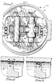
- Fig. 1 is a generally cross-sectional and partially elevational view of a butterfly-type check valve, taken along broken line 1-1 of Fig. 2.
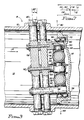
- Fig. 2 is a partially cross-sectional and partially elevational view taken along line 2-2 of Fig. 1.
- Fig. 3 is a partially cross-sectional and partially elevational view taken along line 3-3 of Fig. 1.
- Fig. 4 is a perspective view of a trunnion member and an operatively associated rod.
- Figs. 5 and 6 are partial cross-sectional views illustrating a circumferential sealing arrangement.
- Fig. 7 is a schematic view of a butterfly-type check valve, the view including vectors to illustrate the use of a biasing mechanism to effect initial opening of the valve.
- a mounting body or flow body 10 defines a flow path 12 extending therethrough.
- Arrow 14 indicates the direction of desired flow
- arrow 16 indicates the direction of checked pressure.
- a valve plate assembly is formed by a valve plate 18 and two guide rods 20, 22, which can be hollow rather than solid.
- the rods 20, 22 have flattened ends as indicated in Fig. 4, and are rigidly secured to the valve plate 18 by bolts 24 extending through each end and into tapped bores formed in the plate 18.
- the valve plate 18 has first recesses 26 providing lands for the rods 20, 22, a second recess 28 providing clearance for two trunnion members (hereinafter "trunnions") 30, 32, and two deeper recesses 34, 36 providing clearance for two link members 38, 40 (hereinafter, "links").
- trunnions two trunnion members
- links two link members 38, 40
- Each of the rods 20, 22 extends through an operatively associated one of the trunnions 30, 32.
- Cylindrical bearings 42 are provided to facilitate sliding movement of the rods relative to the trunnions.
- the trunnions (as at 30) have first and second transverse cylindrical portions 44, 46, and the first portion has a bore 48 (Fig. 4) formed therethrough to receive the associated bearing 42 and rod 20.
- Each end of each second cylindrical portion 46 (Fig. 4) is pressed into the inner race of an operatively associated bearing 50.
- each bearing 50 is pressed into an operatively associated one of three support members 52, 54, 56.
- the center support member 54 has a generally tubular portion 58 and a bent cylindrical portion 60, the tubular portion having an inner annular boss 62 (Fig. 2) which serves as a spacer for its operatively associated bearings 50 and trunnions 30, 32.
- the outer support members 52, 56 are bent cylinders having transverse bores 64, 66 formed therein to receive respective bearings 50 and trunnion portions 46 from the inward-facing side, and pins 68 from the outward-facing side.
- the longitudinal axes of the pins 68 are aligned with the pivot axis 90, as determined in the direction indicated by the arrow 86, which should be viewed as extending into the sheet of the drawing at an angle of about four degrees.
- the pins 68 extend from the links 38, 40.
- An additional pair of pins 70 extend from the links and are pressed into bores 72 formed in the valve plate 18.
- the bores 72 extend into a wall 74 formed incident to the formation of the second recess 28. Needle bearings (not shown) are provided between the links and pins.
- fourth and fifth support members 76, 78 (Fig. 3).
- the latter support members extend through bores formed through the flow body 10 and the remaining support members 52, 54, 56, as indicated.
- the ends of the fourth and fifth support members project from the flow body 10 and are threaded to receive nuts 80, or are otherwise rigidly secured to the flow body.
- These support members 76, 78, or their equivalent extend across the flow path 12 at an angle 82 of about four degrees from a line 84 perpendicular to the longitudinal direction 86 of the path.
- This offset geometry is a known expedient for preventing interference between the circumferential edge of the valve plate 18 and the inner, circular-cylindrical surface 88 (Fig. 1) of the flow body. It should also assist in permitting a limited range of translational movement of the plate relative to the pivot axis 90 (Fig. 4), although selective shaping of the inner surface 88 may still be needed to accommodate the required range of translational movement, especially in applications which demand a complete seal at the closed position of the plate 18.
- the support members 52, 54, 56, 76, 78 collectively form a support assembly, the purpose of which is to properly orient and support the valve plate 18 for pivotal movement in the flow path 12. Accordingly, the fourth and fifth support members 76, 78 are provided to secure the remainder of the support assembly to the flow body 10 while preventing movement of the support assembly. Rotational movement of the entire support assembly is prevented by providing both of the fourth and fifth members 76, 78. However, it is clear that only one such member is needed, provided that rotational movement of the same about its own longitudinal axis is prevented. For example, a single member of square cross-section would suffice.
- the support members 52, 54, 56, 76, 78 are suitably bored and tapped to accommodate intersecurement by bolts (as at 92).
- Figs. 5 and 6 illustrate the currently preferred sealing arrangement.
- the valve plate 18 has two annular recesses 94, 95 formed in its circumferential edge.
- An annular V-seal 96 (obtainable from such sources as Furon of Los Alamitos, California) is retained on the recess 94 by a seal 97 which in turn is retained on the angled second recess 95 by shrinkage.
- One leg 98 of the V-seal is entrapped.
- the other leg 100 is flexible about the apex of the seal, and is normally in the position illustrated in Fig. 5. Accordingly, the leg 100 has negative resistance to pressure exerted in the direction 14 of desired flow if the seal is positioned as illustrated in Fig. 6.
- the leg 100 is flexed in a radially outward direction, and is pressed against the inner surface 88 (Fig. 1) by the checked pressure 16.
- a piston housing member 102 having an arcuate bottom surface (not shown) conformal with the inner surface 88 of the flow body 10 is rigidly secured to the latter at a bottom-centered position.
- a piston 104 is slidably disposed in a bore 106 formed in the housing member, and a spring 108 is secured to and interposed in compression between the piston and the bottom of the bore. The spring 108 is maximally compressed when the valve plate 18 is at the illustrated closed position.
- arrows 110, 112, 114 are force vectors representing the center of unchecked pressure, the center of checked pressure, and the biasing force exerted by the piston 104, respectively, when the valve plate 18 is at the closed position.
- the pivot axis 90 is centered in the flow path, and at the closed position the valve plate 18 does not quite reach the zero angle. Accordingly, when the valve 8 is checking, the force 110 is absent and the force 112 is exerted at a point just below the pivot axis 90.
- this force 112 is relatively large compared to the biasing force 114, its associated moment arm is relatively small and the forces 112 and 114 balance or, with the presence of the seal 96, the sum of the associated friction force and the biasing force 114 balance the checking force 112.
- a rotationally-biased traction wheel mounted on and carried with the valve plate 18 should be workable, for example.
- the force exerted in the direction 86 also has a translational component that tends to move the valve plate 18 in a downward direction (as viewed in Fig. 1) parallel to the longitudinal axes of the rods 20, 22. Accordingly, as the plate 18 rotates, the links 38, 40 and pins 68, 70 cooperate with the plate and support members 52, 56 to translationally move the plate relative to the pivot axis 90, and the latter movement is guided by the trunnions 30, 32.
- the translational movement increases the fluid-exerted torque on the plate 18, and the latter continues to translate and rotate. This movement continues until the longitudinal axes of the links 38, 40 are substantially parallel to the rods 20, 22. The movement is reversed in response to pressure associated with transitory back-flow. Note that the range of translational movement is limited to some multiple of the distance between the longitudinal axes of the pins 68, 70.
Landscapes
- Engineering & Computer Science (AREA)
- General Engineering & Computer Science (AREA)
- Mechanical Engineering (AREA)
- Lift Valve (AREA)
Abstract
Claims (7)
- Vanne d'arrêt de type papillon (8) comportant un corps d'écoulement (10) définissant un passage d'écoulement (12); un élément formant support (76), fixé au corps d'écoulement, s'étendant en travers du passage d'écoulement; une plaque de vanne (18) associée à l'élément formant support (76) de sorte que la plaque (18) est susceptible de rotation autour d'un axe de pivotement et que la plaque (18) en position de fermeture ferme le passage d'écoulement (12), caractérisée en ce que la plaque de vanne (18) est susceptible de se déplacer en translation par rapport à l'axe de pivotement lorsque déplacée en rotation; la vanne (8) comportant de plus des moyens de sollicitation (102, 104, 108) pour appliquer une force de sollicitation sur la plaque (18) lorsque la plaque (18) occupe la position de fermeture, la force de sollicitation sollicitant ladite plaque (18) en rotation dans une direction.
- Vanne selon la revendication 1 dans laquelle les moyens de sollicitation comportent un piston (104) sollicité par un ressort.
- Vanne selon la revendication 1 dans laquelle les moyens de sollicitation comportent un piston (104) monté coulissant dans un élément formant boîtier et un ressort (108) associé de façon fonctionnelle au piston (104) et disposé dans l'élément formant boîtier (102).
- Vanne selon la revendication 1 comportant de plus des moyens (68, 70, 38) attachés à la fois à la plaque et à l'élément formant support pour déplacer en translation la plaque lors du mouvement de rotation.
- Vanne selon la revendication 4 dans laquelle les moyens de déplacement comportent deux liaisons mécaniques (38, 40) montées pivotantes sur la plaque et l'élément formant support.
- Vanne selon la revendication 4 dans laquelle les moyens de sollicitation comportent un élément formant boîtier (102) fixé de façon rigide au corps d'écoulement.
- Vanne selon la revendication 6 dans laquelle les moyens de sollicitation comportent de plus un piston (104) monté coulissant dans l'élément de boîtier (102) et un ressort (108) associé de façon fonctionnelle audit piston (104) et disposé dans l'élément formant boîtier (102).
Applications Claiming Priority (3)
| Application Number | Priority Date | Filing Date | Title |
|---|---|---|---|
| US665391 | 1991-03-06 | ||
| US07/665,391 US5056557A (en) | 1991-03-06 | 1991-03-06 | Butterfly-type check valve |
| PCT/US1992/001823 WO1992015808A1 (fr) | 1991-03-06 | 1992-03-04 | Vanne d'arret de type papillon |
Publications (2)
| Publication Number | Publication Date |
|---|---|
| EP0574526A1 EP0574526A1 (fr) | 1993-12-22 |
| EP0574526B1 true EP0574526B1 (fr) | 1994-08-31 |
Family
ID=24669930
Family Applications (1)
| Application Number | Title | Priority Date | Filing Date |
|---|---|---|---|
| EP92908585A Expired - Lifetime EP0574526B1 (fr) | 1991-03-06 | 1992-03-04 | Vanne d'arret de type papillon |
Country Status (4)
| Country | Link |
|---|---|
| US (1) | US5056557A (fr) |
| EP (1) | EP0574526B1 (fr) |
| DE (1) | DE69200368T2 (fr) |
| WO (1) | WO1992015808A1 (fr) |
Families Citing this family (4)
| Publication number | Priority date | Publication date | Assignee | Title |
|---|---|---|---|---|
| US5788220A (en) * | 1996-06-14 | 1998-08-04 | Meziere, Sr.; Gary C. | Linearly actuated gas flow control assembly |
| US6206612B1 (en) | 1999-03-18 | 2001-03-27 | Tim Meyer | Apparatus for preventing contamination of a fresh water source by grey water to be land applied |
| DE102004012507A1 (de) * | 2004-03-15 | 2005-10-06 | Siemens Ag | Drosselklappenstutzen |
| US7325569B2 (en) * | 2005-04-25 | 2008-02-05 | Honeywell International, Inc. | Butterfly valve with integral split flapper relief valve |
Family Cites Families (6)
| Publication number | Priority date | Publication date | Assignee | Title |
|---|---|---|---|---|
| US2641485A (en) * | 1949-07-26 | 1953-06-09 | Guillaume M Dupuy | Valved pipe fitting |
| GB1180305A (en) * | 1967-10-20 | 1970-02-04 | Kazuo Kitazawa | Improvements in and relating to Butterfly Valves |
| US4280681A (en) * | 1980-01-09 | 1981-07-28 | Koppers Company, Inc. | Center link disc valve |
| DE3508318C1 (de) * | 1985-03-08 | 1986-07-24 | Schertler, Siegfried, Haag | Absperrklappe |
| DE3677908D1 (de) * | 1985-05-30 | 1991-04-11 | Fritz Schmidt | Absperrorgan fuer rohrleitungen. |
| US4964422A (en) * | 1989-08-17 | 1990-10-23 | Allied-Signal Inc. | Butterfly-type check valve |
-
1991
- 1991-03-06 US US07/665,391 patent/US5056557A/en not_active Expired - Fee Related
-
1992
- 1992-03-04 EP EP92908585A patent/EP0574526B1/fr not_active Expired - Lifetime
- 1992-03-04 DE DE69200368T patent/DE69200368T2/de not_active Expired - Fee Related
- 1992-03-04 WO PCT/US1992/001823 patent/WO1992015808A1/fr not_active Ceased
Also Published As
| Publication number | Publication date |
|---|---|
| DE69200368T2 (de) | 1994-12-22 |
| DE69200368D1 (de) | 1994-10-06 |
| WO1992015808A1 (fr) | 1992-09-17 |
| EP0574526A1 (fr) | 1993-12-22 |
| US5056557A (en) | 1991-10-15 |
Similar Documents
| Publication | Publication Date | Title |
|---|---|---|
| US4330006A (en) | Damping device for check valves | |
| EP0409445B1 (fr) | Ferme-porte | |
| US4419786A (en) | Door closer assembly | |
| EP0555271B1 (fr) | Mecanisme d'arret automatique | |
| CA2002747C (fr) | Robinet-vanne muni d'un actionneur | |
| EP0574526B1 (fr) | Vanne d'arret de type papillon | |
| US9816632B2 (en) | Actuated valve system triggered by the failure of a collapsible pin under overpressure condition | |
| JPH10148265A (ja) | 回転弁組立体 | |
| US5000213A (en) | Butterfly valve method and apparatus | |
| US4073467A (en) | High pressure pinch valve | |
| US5005804A (en) | Balanced-torque butterfly valve | |
| US5046527A (en) | Butterfly-type check valve | |
| GB2105824A (en) | Hydraulic friction coupling with servo actuator | |
| US4586538A (en) | Spindle valve for a tube system for liquids | |
| US5029599A (en) | Butterfly valve method and apparatus | |
| US5029809A (en) | Valve-control device and valve having such a control device | |
| EP0297976B1 (fr) | Dispositif de transmission étanche à soufflet métallique notamment pour vannes à simple rotation quart de tour | |
| US4967997A (en) | Butterfly valve with intra-shaft actuator means | |
| EP0409485B1 (fr) | Ferme-porte | |
| EP1001201A2 (fr) | Mécanisme à levier verrouillable | |
| US4450732A (en) | Device for imposing the linear and angular movement to the valve stem | |
| US20040151599A1 (en) | Continuously blockable arresting device | |
| EP0994284A1 (fr) | Actionneur pneumatique avec des pistons à section transversale non-ronde | |
| EP0939242B1 (fr) | Dispositif commandant le mouvement | |
| EP0479941B1 (fr) | Robinet papillon a force de torsion equilibree |
Legal Events
| Date | Code | Title | Description |
|---|---|---|---|
| PUAI | Public reference made under article 153(3) epc to a published international application that has entered the european phase |
Free format text: ORIGINAL CODE: 0009012 |
|
| 17P | Request for examination filed |
Effective date: 19930820 |
|
| AK | Designated contracting states |
Kind code of ref document: A1 Designated state(s): DE FR GB |
|
| 17Q | First examination report despatched |
Effective date: 19931223 |
|
| RAP1 | Party data changed (applicant data changed or rights of an application transferred) |
Owner name: ALLIEDSIGNAL INC. |
|
| GRAA | (expected) grant |
Free format text: ORIGINAL CODE: 0009210 |
|
| AK | Designated contracting states |
Kind code of ref document: B1 Designated state(s): DE FR GB |
|
| PG25 | Lapsed in a contracting state [announced via postgrant information from national office to epo] |
Ref country code: FR Free format text: THE PATENT HAS BEEN ANNULLED BY A DECISION OF A NATIONAL AUTHORITY Effective date: 19940831 |
|
| REF | Corresponds to: |
Ref document number: 69200368 Country of ref document: DE Date of ref document: 19941006 |
|
| ET | Fr: translation filed | ||
| PLBE | No opposition filed within time limit |
Free format text: ORIGINAL CODE: 0009261 |
|
| 26N | No opposition filed | ||
| PG25 | Lapsed in a contracting state [announced via postgrant information from national office to epo] |
Ref country code: DE Effective date: 19951201 |
|
| PG25 | Lapsed in a contracting state [announced via postgrant information from national office to epo] |
Ref country code: GB Effective date: 19960304 |
|
| REG | Reference to a national code |
Ref country code: FR Ref legal event code: ST |
|
| GBPC | Gb: european patent ceased through non-payment of renewal fee |
Effective date: 19960304 |