EP0574736A1 - Outil de perçage et de meulage de matériaux osseux - Google Patents
Outil de perçage et de meulage de matériaux osseux Download PDFInfo
- Publication number
- EP0574736A1 EP0574736A1 EP93108384A EP93108384A EP0574736A1 EP 0574736 A1 EP0574736 A1 EP 0574736A1 EP 93108384 A EP93108384 A EP 93108384A EP 93108384 A EP93108384 A EP 93108384A EP 0574736 A1 EP0574736 A1 EP 0574736A1
- Authority
- EP
- European Patent Office
- Prior art keywords
- grinding
- grinding head
- face
- drilling tool
- tool according
- Prior art date
- Legal status (The legal status is an assumption and is not a legal conclusion. Google has not performed a legal analysis and makes no representation as to the accuracy of the status listed.)
- Granted
Links
Images


Classifications
-
- A—HUMAN NECESSITIES
- A61—MEDICAL OR VETERINARY SCIENCE; HYGIENE
- A61B—DIAGNOSIS; SURGERY; IDENTIFICATION
- A61B17/00—Surgical instruments, devices or methods
- A61B17/16—Instruments for performing osteoclasis; Drills or chisels for bones; Trepans
- A61B17/1637—Hollow drills or saws producing a curved cut, e.g. cylindrical
Definitions
- the invention relates to an abrasive drilling tool for bone material, consisting of a hollow cylindrical tool shaft, which carries at its front end an annular grinding head, which is coated with abrasive grain material on its surface.
- grinding drilling tools are used to prepare the removal of bone material and to prepare an implant bed.
- the tools working according to the grinding method have the advantage that they do not tear or similar when they come into contact with soft tissue Cause injury.
- the object of the invention is therefore to design a grinding / drilling tool of the type mentioned at the outset such that the grinding head guides itself laterally when penetrating relatively soft material, so that lateral migration of the grinding head is effectively prevented.
- This object is achieved in that the end face of the grinding head is connected at its inner and / or outer edge with sharp edges to the adjacent inner or outer cylindrical side wall of the grinding head.
- the end face of the grinding head is a circular ring surface running perpendicular to the longitudinal axis of the tool.
- This end face is preferably designed with sharp edges on its two edges. This will make it cleaner Separation process on both the outer and the inner edge of the end face of the grinding head, while the end face covered with abrasive grain material itself takes over the entire material removal.
- the end face of the grinding head can be an annular outer truncated cone surface, which forms a sharp-edged acute angle with the inner side wall of the grinding head on its inner edge, or it can be an inner annular hollow truncated cone surface, which is one on its outer edge forms a sharp-edged acute angle with the outer side wall of the grinding head.
- the conical shape of the end face ensures that one edge forms an acute angle with the adjacent side face and is therefore particularly well suited for a clean separation process even when penetrating cartilage and similar material.
- the grinding head is advantageously designed with an overhang of at least approximately 10% of the wall thickness of the tool shaft relative to the outer wall and the inner wall of the hollow cylindrical tool shaft.
- This rear overhang of the grinding head prevents the wall of the processed bone or cartilage material from coming into closer contact with the tool shank.
- the avoidance or reduction of the contact between the bone or cartilage and the hollow cylindrical tool shaft prevents the tool from being braked and the tissue in the contact area being heated by friction. Furthermore interruption of the flow of the coolant, which is usually supplied inside the tool shank, is prevented.
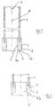
- the grinding and boring tool shown in FIG. 1 is used to process bone material in medical technology, in particular to prepare for the removal of Bone material and the preparation of bone implants.
- the grinding / drilling tool is intended to be held in a chuck (not shown) of a drill used in medical technology.
- a hollow cylindrical tool shank 1 has at its rear end a driver groove 2 into which a driver (not shown) of the chuck of the drilling machine engages. Coolant is usually supplied in the interior of the tool shank 1.
- the tool shaft 1 carries at its front end an annular grinding head 3, which is preferably also hollow cylindrical.
- the surface of the grinding head is coated with abrasive grain material, usually diamond grains or corundum grains.
- the coating formed in this way forms the abrasive material which removes the bone or cartilage into which the abrasive drilling tool penetrates.
- the grinding head 3 can consist of the abrasive grain material throughout.
- the grinding head 3 has a flat end face 4 which runs perpendicular to the longitudinal axis 2a of the tool and has sharp edges on its inner edge 4a and its outer edge 4b on the adjacent inner cylindrical side wall 5 or outer cylindrical side wall 6 of the grinding head 3 connects.
- This sharp-edged design of the end face 4 causes the grinding head 3 to penetrate into the bone or cartilage material to be removed with a cleanly limited cut. This ensures effective lateral guidance of the grinding / drilling tool at the machining point.
- the exemplary embodiment shown in FIG. 2 differs from the exemplary embodiment according to FIG. 1 only in that the end face 4 'of the grinding head 3 as an inner annular hollow truncated cone surface is executed, which forms a sharp-edged acute angle with the outer side wall 6 of the grinding head 3 at its outer edge 4'b.
- the end face 4 ′′ is designed as an outer annular truncated cone surface, which forms a sharp-edged acute angle with the inner side wall 5 of the grinding head 3 on its inner edge 4 ′′ a. It is understood that in the embodiments according to FIGS. 2 and 3 the sharp-edged edge 4'b or 4''a takes over the guidance of the grinding / drilling tool in the bone or cartilage material.
- the grinding head 3 has at its rear end facing away from the end face 4, 4 ′ or 4 ′′ relative to the inner wall 1a and the outer wall 1b of the hollow cylindrical tool shank 1, a protrusion 7 which is at least about 10% the wall thickness of the tool shank is 1.
- This protrusion 7 prevents a noticeable contact with the tool shaft 1 when the grinding head 3 penetrates into the material to be removed. This prevents the tool from decelerating and prevents undesirable heat generation due to friction.
- Fig. 4 shows an abrasive drilling tool similar to Fig. 1, but at least two opposing coolant slots 8 are provided, which extend from the end face 4 to the rear, which pass from the inner side wall 5 to the outer side wall 6 of the grinding head 3. Since the coolant is supplied in the interior of the tool shank 1 and since there is an extensive seal between the end face 4 and the surface to be machined, this enables Coolant slots 8 a coolant flow, so that a sufficient cooling effect in the processing area and in particular a removal of the removed material are ensured.
- radially continuous coolant bores 9 can also be provided in the grinding head 3, which are shown in FIG. 5.
- coolant grooves 10 and 11 are provided in the inner side wall 5 and the outer side wall 6 of the grinding head 3.
Landscapes
- Health & Medical Sciences (AREA)
- Surgery (AREA)
- Life Sciences & Earth Sciences (AREA)
- Medical Informatics (AREA)
- Animal Behavior & Ethology (AREA)
- Orthopedic Medicine & Surgery (AREA)
- Oral & Maxillofacial Surgery (AREA)
- Engineering & Computer Science (AREA)
- Biomedical Technology (AREA)
- Heart & Thoracic Surgery (AREA)
- Dentistry (AREA)
- Molecular Biology (AREA)
- Nuclear Medicine, Radiotherapy & Molecular Imaging (AREA)
- General Health & Medical Sciences (AREA)
- Public Health (AREA)
- Veterinary Medicine (AREA)
- Surgical Instruments (AREA)
- Polishing Bodies And Polishing Tools (AREA)
- Dental Tools And Instruments Or Auxiliary Dental Instruments (AREA)
- Materials For Medical Uses (AREA)
Applications Claiming Priority (2)
| Application Number | Priority Date | Filing Date | Title |
|---|---|---|---|
| DE4218722A DE4218722A1 (de) | 1992-06-06 | 1992-06-06 | Schleif-Bohrwerkzeug für Knochenmaterial |
| DE4218722 | 1992-06-06 |
Publications (2)
| Publication Number | Publication Date |
|---|---|
| EP0574736A1 true EP0574736A1 (fr) | 1993-12-22 |
| EP0574736B1 EP0574736B1 (fr) | 1996-07-17 |
Family
ID=6460541
Family Applications (1)
| Application Number | Title | Priority Date | Filing Date |
|---|---|---|---|
| EP93108384A Expired - Lifetime EP0574736B1 (fr) | 1992-06-06 | 1993-05-25 | Outil de perçage et de meulage de matériaux osseux |
Country Status (5)
| Country | Link |
|---|---|
| EP (1) | EP0574736B1 (fr) |
| AT (1) | ATE140374T1 (fr) |
| DE (2) | DE4218722A1 (fr) |
| DK (1) | DK0574736T3 (fr) |
| ES (1) | ES2090773T3 (fr) |
Cited By (5)
| Publication number | Priority date | Publication date | Assignee | Title |
|---|---|---|---|---|
| EP0990421A1 (fr) * | 1998-09-29 | 2000-04-05 | Sulzer Orthopädie AG | Fraise creuse pour tissus |
| EP1175870A1 (fr) * | 2000-07-26 | 2002-01-30 | Sulzer Orthopedics Ltd. | Mèches creuses pour l'obtention de matériau osseux |
| EP1226785A1 (fr) * | 2001-01-24 | 2002-07-31 | Draenert, Klaus, Prof.Dr.med. | Outil de rectification de forme |
| WO2004082484A1 (fr) * | 2003-03-18 | 2004-09-30 | Carlo Bianchini | Dispositif pour biopsie medullaire |
| DE102015208610A1 (de) * | 2015-05-08 | 2016-11-10 | Frank Zastrow | Chirurgisches Werkzeug |
Citations (4)
| Publication number | Priority date | Publication date | Assignee | Title |
|---|---|---|---|---|
| WO1983002553A1 (fr) * | 1982-01-25 | 1983-08-04 | Draenert, Klaus | Instrument chirurgical de prelevement de tissus osseux par abrasion |
| GB2140336A (en) * | 1983-05-25 | 1984-11-28 | Robert S Bray | Surgical methods and apparatus for bone removal |
| FR2625429A1 (fr) * | 1988-01-06 | 1989-07-07 | Loire Const Meca Precision | Trocard mecanise, pour la pratique d'operations chirurgicales |
| US5055105A (en) * | 1989-10-11 | 1991-10-08 | Bowen & Company, Ltd. | Bone drill bit |
-
1992
- 1992-06-06 DE DE4218722A patent/DE4218722A1/de not_active Withdrawn
-
1993
- 1993-05-25 DK DK93108384.4T patent/DK0574736T3/da active
- 1993-05-25 EP EP93108384A patent/EP0574736B1/fr not_active Expired - Lifetime
- 1993-05-25 ES ES93108384T patent/ES2090773T3/es not_active Expired - Lifetime
- 1993-05-25 DE DE59303236T patent/DE59303236D1/de not_active Expired - Fee Related
- 1993-05-25 AT AT93108384T patent/ATE140374T1/de active
Patent Citations (4)
| Publication number | Priority date | Publication date | Assignee | Title |
|---|---|---|---|---|
| WO1983002553A1 (fr) * | 1982-01-25 | 1983-08-04 | Draenert, Klaus | Instrument chirurgical de prelevement de tissus osseux par abrasion |
| GB2140336A (en) * | 1983-05-25 | 1984-11-28 | Robert S Bray | Surgical methods and apparatus for bone removal |
| FR2625429A1 (fr) * | 1988-01-06 | 1989-07-07 | Loire Const Meca Precision | Trocard mecanise, pour la pratique d'operations chirurgicales |
| US5055105A (en) * | 1989-10-11 | 1991-10-08 | Bowen & Company, Ltd. | Bone drill bit |
Cited By (5)
| Publication number | Priority date | Publication date | Assignee | Title |
|---|---|---|---|---|
| EP0990421A1 (fr) * | 1998-09-29 | 2000-04-05 | Sulzer Orthopädie AG | Fraise creuse pour tissus |
| EP1175870A1 (fr) * | 2000-07-26 | 2002-01-30 | Sulzer Orthopedics Ltd. | Mèches creuses pour l'obtention de matériau osseux |
| EP1226785A1 (fr) * | 2001-01-24 | 2002-07-31 | Draenert, Klaus, Prof.Dr.med. | Outil de rectification de forme |
| WO2004082484A1 (fr) * | 2003-03-18 | 2004-09-30 | Carlo Bianchini | Dispositif pour biopsie medullaire |
| DE102015208610A1 (de) * | 2015-05-08 | 2016-11-10 | Frank Zastrow | Chirurgisches Werkzeug |
Also Published As
| Publication number | Publication date |
|---|---|
| ES2090773T3 (es) | 1996-10-16 |
| EP0574736B1 (fr) | 1996-07-17 |
| DE4218722A1 (de) | 1993-12-09 |
| DE59303236D1 (de) | 1996-08-22 |
| DK0574736T3 (da) | 1996-10-07 |
| ATE140374T1 (de) | 1996-08-15 |
Similar Documents
| Publication | Publication Date | Title |
|---|---|---|
| DE3718731C2 (fr) | ||
| EP1066801B1 (fr) | Procédé et dispositif pour fabriquer des prothèses médicales en particulier dentaires | |
| DE102012110253A1 (de) | Medizinische Fräse mit Absaugung | |
| DE3024852C2 (fr) | ||
| DE102021105703B4 (de) | Bohrwerkzeug und Verfahren zum Erzeugen einer Bohrung | |
| EP0574736B1 (fr) | Outil de perçage et de meulage de matériaux osseux | |
| DE69724565T2 (de) | Eckenfräser mit Schneideinsätzen | |
| DE19728384A1 (de) | Rotierendes Schaftwerkzeug | |
| DE102020000882A1 (de) | Verfahren zum Herstellen eines Werkstücks, insbesondere einer Turbinenschaufel, mit einem Fräswerkzeug | |
| EP3093089A1 (fr) | Outil de rotation | |
| EP3031560A1 (fr) | Outil d'usinage et plaque de coupe pour l'outil d'usinage | |
| EP3436211B1 (fr) | Outil d'alésoir avec listel | |
| DE3119533A1 (de) | "vorrichtung zum mechanischen bearbeiten ringfoermiger werkstuecke" | |
| WO2006024536A1 (fr) | Procede et dispositif pour affuter un outil de coupe, notamment un couteau | |
| CH631379A5 (de) | Verfahren zum erreichen eines staubfreien schnittes bei mineralwollschichten und vorrichtung zur durchfuehrung des verfahrens. | |
| EP3507044B1 (fr) | Outil de fraisage à un seul tranchant | |
| DE10356731B3 (de) | Fräskopf für einen Hohl- oder Schaftfräser | |
| DE202019005299U1 (de) | Fräswerkzeug mit Zentrierwirkung | |
| DE102004040581B4 (de) | Knochenfräse | |
| DE2820810A1 (de) | Schaelmesser fuer schaelmaschinen mit umlaufendem messerkopf | |
| DE102010027496B4 (de) | Fräswerkzeug | |
| DE10022047C1 (de) | Knochenfräse | |
| EP1004414A2 (fr) | Outil de coupe de la pierre ayant des segments de coupe de pcd | |
| EP0512275B1 (fr) | Outil de fraisage rotatif | |
| EP1077121B1 (fr) | Fraise |
Legal Events
| Date | Code | Title | Description |
|---|---|---|---|
| PUAI | Public reference made under article 153(3) epc to a published international application that has entered the european phase |
Free format text: ORIGINAL CODE: 0009012 |
|
| AK | Designated contracting states |
Kind code of ref document: A1 Designated state(s): AT BE CH DE DK ES FR GB IE IT LI LU NL PT SE |
|
| 17P | Request for examination filed |
Effective date: 19940520 |
|
| 17Q | First examination report despatched |
Effective date: 19941006 |
|
| GRAH | Despatch of communication of intention to grant a patent |
Free format text: ORIGINAL CODE: EPIDOS IGRA |
|
| GRAA | (expected) grant |
Free format text: ORIGINAL CODE: 0009210 |
|
| AK | Designated contracting states |
Kind code of ref document: B1 Designated state(s): AT BE CH DE DK ES FR GB IE IT LI LU NL PT SE |
|
| REF | Corresponds to: |
Ref document number: 140374 Country of ref document: AT Date of ref document: 19960815 Kind code of ref document: T |
|
| REG | Reference to a national code |
Ref country code: IE Ref legal event code: FG4D Free format text: 69142 |
|
| REF | Corresponds to: |
Ref document number: 59303236 Country of ref document: DE Date of ref document: 19960822 |
|
| ITF | It: translation for a ep patent filed | ||
| GBT | Gb: translation of ep patent filed (gb section 77(6)(a)/1977) |
Effective date: 19960830 |
|
| REG | Reference to a national code |
Ref country code: DK Ref legal event code: T3 |
|
| REG | Reference to a national code |
Ref country code: ES Ref legal event code: FG2A Ref document number: 2090773 Country of ref document: ES Kind code of ref document: T3 |
|
| ET | Fr: translation filed | ||
| ET | Fr: translation filed | ||
| REG | Reference to a national code |
Ref country code: ES Ref legal event code: FG2A Ref document number: 2090773 Country of ref document: ES Kind code of ref document: T3 |
|
| SC4A | Pt: translation is available |
Free format text: 960911 AVAILABILITY OF NATIONAL TRANSLATION |
|
| PLBE | No opposition filed within time limit |
Free format text: ORIGINAL CODE: 0009261 |
|
| 26N | No opposition filed | ||
| PGFP | Annual fee paid to national office [announced via postgrant information from national office to epo] |
Ref country code: DK Payment date: 19980515 Year of fee payment: 6 |
|
| PGFP | Annual fee paid to national office [announced via postgrant information from national office to epo] |
Ref country code: PT Payment date: 19980520 Year of fee payment: 6 |
|
| PGFP | Annual fee paid to national office [announced via postgrant information from national office to epo] |
Ref country code: LU Payment date: 19980522 Year of fee payment: 6 |
|
| PGFP | Annual fee paid to national office [announced via postgrant information from national office to epo] |
Ref country code: IE Payment date: 19980528 Year of fee payment: 6 |
|
| PGFP | Annual fee paid to national office [announced via postgrant information from national office to epo] |
Ref country code: NL Payment date: 19980531 Year of fee payment: 6 |
|
| PGFP | Annual fee paid to national office [announced via postgrant information from national office to epo] |
Ref country code: BE Payment date: 19980714 Year of fee payment: 6 |
|
| PGFP | Annual fee paid to national office [announced via postgrant information from national office to epo] |
Ref country code: SE Payment date: 19990414 Year of fee payment: 7 |
|
| PGFP | Annual fee paid to national office [announced via postgrant information from national office to epo] |
Ref country code: FR Payment date: 19990511 Year of fee payment: 7 |
|
| PGFP | Annual fee paid to national office [announced via postgrant information from national office to epo] |
Ref country code: AT Payment date: 19990512 Year of fee payment: 7 |
|
| PGFP | Annual fee paid to national office [announced via postgrant information from national office to epo] |
Ref country code: GB Payment date: 19990519 Year of fee payment: 7 |
|
| PGFP | Annual fee paid to national office [announced via postgrant information from national office to epo] |
Ref country code: ES Payment date: 19990524 Year of fee payment: 7 |
|
| PG25 | Lapsed in a contracting state [announced via postgrant information from national office to epo] |
Ref country code: LU Free format text: LAPSE BECAUSE OF NON-PAYMENT OF DUE FEES Effective date: 19990525 Ref country code: IE Free format text: LAPSE BECAUSE OF NON-PAYMENT OF DUE FEES Effective date: 19990525 |
|
| PGFP | Annual fee paid to national office [announced via postgrant information from national office to epo] |
Ref country code: CH Payment date: 19990526 Year of fee payment: 7 |
|
| PGFP | Annual fee paid to national office [announced via postgrant information from national office to epo] |
Ref country code: DE Payment date: 19990528 Year of fee payment: 7 |
|
| PG25 | Lapsed in a contracting state [announced via postgrant information from national office to epo] |
Ref country code: DK Free format text: LAPSE BECAUSE OF NON-PAYMENT OF DUE FEES Effective date: 19990531 Ref country code: BE Free format text: LAPSE BECAUSE OF NON-PAYMENT OF DUE FEES Effective date: 19990531 |
|
| BERE | Be: lapsed |
Owner name: MERCK PATENT G.M.B.H. Effective date: 19990531 |
|
| PG25 | Lapsed in a contracting state [announced via postgrant information from national office to epo] |
Ref country code: PT Free format text: LAPSE BECAUSE OF NON-PAYMENT OF DUE FEES Effective date: 19991130 |
|
| PG25 | Lapsed in a contracting state [announced via postgrant information from national office to epo] |
Ref country code: NL Free format text: LAPSE BECAUSE OF NON-PAYMENT OF DUE FEES Effective date: 19991201 |
|
| NLV4 | Nl: lapsed or anulled due to non-payment of the annual fee |
Effective date: 19991201 |
|
| REG | Reference to a national code |
Ref country code: DK Ref legal event code: EBP |
|
| REG | Reference to a national code |
Ref country code: PT Ref legal event code: MM4A Free format text: LAPSE DUE TO NON-PAYMENT OF FEES Effective date: 19991130 |
|
| PG25 | Lapsed in a contracting state [announced via postgrant information from national office to epo] |
Ref country code: GB Free format text: LAPSE BECAUSE OF NON-PAYMENT OF DUE FEES Effective date: 20000525 Ref country code: AT Free format text: LAPSE BECAUSE OF NON-PAYMENT OF DUE FEES Effective date: 20000525 |
|
| PG25 | Lapsed in a contracting state [announced via postgrant information from national office to epo] |
Ref country code: SE Free format text: LAPSE BECAUSE OF NON-PAYMENT OF DUE FEES Effective date: 20000526 Ref country code: ES Free format text: THE PATENT HAS BEEN ANNULLED BY A DECISION OF A NATIONAL AUTHORITY Effective date: 20000526 |
|
| PG25 | Lapsed in a contracting state [announced via postgrant information from national office to epo] |
Ref country code: LI Free format text: LAPSE BECAUSE OF NON-PAYMENT OF DUE FEES Effective date: 20000531 Ref country code: CH Free format text: LAPSE BECAUSE OF NON-PAYMENT OF DUE FEES Effective date: 20000531 |
|
| REG | Reference to a national code |
Ref country code: CH Ref legal event code: PL |
|
| GBPC | Gb: european patent ceased through non-payment of renewal fee |
Effective date: 20000525 |
|
| EUG | Se: european patent has lapsed |
Ref document number: 93108384.4 |
|
| PG25 | Lapsed in a contracting state [announced via postgrant information from national office to epo] |
Ref country code: FR Free format text: LAPSE BECAUSE OF NON-PAYMENT OF DUE FEES Effective date: 20010131 |
|
| PG25 | Lapsed in a contracting state [announced via postgrant information from national office to epo] |
Ref country code: DE Free format text: LAPSE BECAUSE OF NON-PAYMENT OF DUE FEES Effective date: 20010301 |
|
| REG | Reference to a national code |
Ref country code: FR Ref legal event code: ST |
|
| REG | Reference to a national code |
Ref country code: ES Ref legal event code: FD2A Effective date: 20020304 |
|
| PG25 | Lapsed in a contracting state [announced via postgrant information from national office to epo] |
Ref country code: IT Free format text: LAPSE BECAUSE OF NON-PAYMENT OF DUE FEES;WARNING: LAPSES OF ITALIAN PATENTS WITH EFFECTIVE DATE BEFORE 2007 MAY HAVE OCCURRED AT ANY TIME BEFORE 2007. THE CORRECT EFFECTIVE DATE MAY BE DIFFERENT FROM THE ONE RECORDED. Effective date: 20050525 |