EP0574765A1 - Procédé et dispositif pour le soudage pour résistance en tôle de matière à haute conductibilité - Google Patents
Procédé et dispositif pour le soudage pour résistance en tôle de matière à haute conductibilité Download PDFInfo
- Publication number
- EP0574765A1 EP0574765A1 EP93108778A EP93108778A EP0574765A1 EP 0574765 A1 EP0574765 A1 EP 0574765A1 EP 93108778 A EP93108778 A EP 93108778A EP 93108778 A EP93108778 A EP 93108778A EP 0574765 A1 EP0574765 A1 EP 0574765A1
- Authority
- EP
- European Patent Office
- Prior art keywords
- electrode
- welding
- disk
- contact spring
- highly conductive
- Prior art date
- Legal status (The legal status is an assumption and is not a legal conclusion. Google has not performed a legal analysis and makes no representation as to the accuracy of the status listed.)
- Withdrawn
Links
- 238000003466 welding Methods 0.000 title claims abstract description 49
- 238000000034 method Methods 0.000 title claims description 16
- 239000000463 material Substances 0.000 title claims description 6
- 239000012876 carrier material Substances 0.000 abstract description 4
- 239000002184 metal Substances 0.000 abstract description 2
- 238000004519 manufacturing process Methods 0.000 description 5
- 210000002445 nipple Anatomy 0.000 description 5
- 239000004020 conductor Substances 0.000 description 2
- 230000002093 peripheral effect Effects 0.000 description 2
- 208000000260 Warts Diseases 0.000 description 1
- 230000001070 adhesive effect Effects 0.000 description 1
- 238000005452 bending Methods 0.000 description 1
- 238000003825 pressing Methods 0.000 description 1
- 201000010153 skin papilloma Diseases 0.000 description 1
Images
Classifications
-
- B—PERFORMING OPERATIONS; TRANSPORTING
- B23—MACHINE TOOLS; METAL-WORKING NOT OTHERWISE PROVIDED FOR
- B23K—SOLDERING OR UNSOLDERING; WELDING; CLADDING OR PLATING BY SOLDERING OR WELDING; CUTTING BY APPLYING HEAT LOCALLY, e.g. FLAME CUTTING; WORKING BY LASER BEAM
- B23K11/00—Resistance welding; Severing by resistance heating
- B23K11/10—Spot welding; Stitch welding
- B23K11/11—Spot welding
- B23K11/115—Spot welding by means of two electrodes placed opposite one another on both sides of the welded parts
-
- B—PERFORMING OPERATIONS; TRANSPORTING
- B23—MACHINE TOOLS; METAL-WORKING NOT OTHERWISE PROVIDED FOR
- B23K—SOLDERING OR UNSOLDERING; WELDING; CLADDING OR PLATING BY SOLDERING OR WELDING; CUTTING BY APPLYING HEAT LOCALLY, e.g. FLAME CUTTING; WORKING BY LASER BEAM
- B23K11/00—Resistance welding; Severing by resistance heating
- B23K11/30—Features relating to electrodes
- B23K11/3036—Roller electrodes
Definitions
- the invention relates to a method and a device for resistance welding of highly conductive sheet metal on a highly conductive carrier material, in particular of contact springs of a relay on a rigid carrier.
- contact springs must be electrically and mechanically connected to spring supports.
- highly conductive material has to be used and on the other hand that the spring material is subjected to high mechanical loads during operation.
- highly conductive material is generally not good for resistance welding.
- the tendency to stick to the welding electrodes leads to problems in automatic production processors.
- the welding point which is thermally and mechanically damaged by the welding, is also the clamping point, that is the most heavily loaded zone of the contact spring. Often it cannot be protected against overload by additional constructive measures.
- the welding current flows through the defined welding point in a concentrated manner.
- This can be achieved, for example, by a convexly curved, approximately conical or nose-shaped electrode, as is shown, for example, in EP-A-0 000 876.
- the smaller the radius at the tip of the electrode the faster it burns and the shorter its service life in automatic production.
- mass articles such as contact springs for relays, are welded between flat electrodes in automatic production, the welding point itself being defined by welding nipples which are previously embossed into the carrier material for the contact spring.
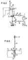
- FIG. 3 A contact spring 31 is to be welded onto a spring support 32. It is clamped between the flat ends of the welding electrodes 33 and 34. In order to obtain defined welding points, two welding nipples 35, on which the contact spring 31 rests, are embossed in the spring carrier 32. However, these welding nipples 35 generally do not melt down to the surface of the spring carrier 32, so that the contact spring hangs freely on an increase in the spring carrier after welding. This leads to additional transverse stresses. Since a gap 36 also remains between the spring support 32 and the contact spring 31, the contact spring cannot be supported on the spring support edge 38 when loaded in the direction of the arrow 37. The contact spring is loaded with the highest voltages at the welding point, i.e.
- the object of the invention is a method and an apparatus Specify for resistance welding of highly conductive sheet materials, in which the problems mentioned are solved or avoided, so that a reliable and resilient welding point is achieved, but at the same time a long service life of the electrodes is ensured in the production of large quantities.
- welding is therefore carried out without weld nipples.
- the current can flow through the materials in the shortest possible way, so that the welding power is optimally used and does not have to be dimensioned too high.
- the spring lies flat on the spring support and can be supported on the edge of the spring support. The welding point is therefore only slightly loaded during the operational spring movement. Adhesive effects during welding do not occur, nor are there any transverse stresses.
- the disk-shaped electrode used in the invention which is rotated by a certain angular step after a predetermined number of welds, a large number of welding processes can be carried out before the electrode has to be reworked or replaced.
- the service life of this electrode can therefore be considerably longer than that of a pin-shaped electrode with a curved surface.
- a disk-shaped electrode is used in which the radius of curvature on the circumference of the electrode in the planes perpendicular to the plane of the disk is smaller than the circumferential radius of the disk.
- a ratio of the order of 2: 1 can preferably be used. Due to the different radii of curvature of the pane itself and the circumference of the pane perpendicular to the plane of the pane, an elliptical welding spot is created.
- the electrode is placed on the sheet to be welded in such a way that the longer axis of the welding ellipse is parallel to the bending axis of the spring sheet in question when the welded spring sheet, for example in the form of a contact spring, is to be subjected to operational pivoting .
- An inventive device for resistance welding has an electrode holder in the form of an axial bearing for the disk-shaped electrode and a device for rotating the disk-shaped electrode in each case by a certain angular step.
- a suitable control for this furthermore has a device which counts the number of welds in a specific angular position of the disk-shaped electrode and rotates the electrode further by a specific angular step when a predetermined number of welds is reached.
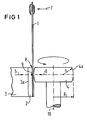
- the arrangement shown in FIG. 1 for welding a contact spring 1 onto a spring support 2 contains a first electrode 3 with a flat electrode surface 3a and a disk-shaped electrode 4 with a radius R, which has a convex curve with the radius r on its peripheral edge 4a.
- the contact spring 1 When carrying out this welding method, the contact spring 1 is placed flat on the spring support 2 and the contact spring 1 and the spring support 2 are welded by pressing the two electrodes 3 and 4 in the direction of the arrows 5 and 6 and by applying an appropriate welding current. Since the contact spring 1 lies flat, it can be supported during operation in the direction of arrow 7 on the edge 8 of the spring support 2, so that the weld 9 is relieved. After a predetermined number of welds, the electrode 4 is rotated further about its axis 10 by a certain angular step, so that a peripheral surface location which has not yet been worn rests on the contact spring during the further welds.
- a possible actuation arrangement for the disk-shaped electrode 4 is outlined schematically in FIG. Again, a flat counter electrode 3 can be seen, against which the spring support 2 and the contact spring 1 rest.
- the electrode 4 is mounted on a shaft 11 so that it can be rotated about its axis in the circular direction 12 and can be pivoted about its mounting 13 in the direction of the double arrow 14.
- a Clock generator 15 for the welding cycle actuates a piston rod 17 in the direction of the double arrow 18 in each cycle step via a cylinder 16, so that the electrode 4 with its shaft 11 is first pivoted away from the counter electrode 3 so that a new contact spring 1 with a spring carrier 2 in the welding position can be brought.
- the disc-shaped electrode 4 is then pivoted back and pressed onto the contact spring 1.
- the number of pulses from the clock generator 15 is counted in a divider 19. If a predetermined number of clock pulses corresponding to the same number of welding processes has been paid, the divider 19 sends a pulse to the cylinder 20 which, via a finger 21 in the direction of the double arrow 22, engages a gearwheel 23 fixedly connected to the shaft 11 by a predetermined angular step Continues to turn in the direction of arrow 24. A new circumferential location of the electrode 4 is thus used for the subsequent welding processes.
- FIG. 2 The structure shown in FIG. 2 is also only a schematic example. So it would also be conceivable to mount the electrode 4 only rotatable about an axis and not pivotable, while the electrode 3 for each Change of the workpiece can be pivoted back. Otherwise, the current supply to the electrodes and their control is not specifically shown in FIG. 2, since these are familiar to any person skilled in the art.
Landscapes
- Engineering & Computer Science (AREA)
- Mechanical Engineering (AREA)
- Resistance Welding (AREA)
Applications Claiming Priority (2)
| Application Number | Priority Date | Filing Date | Title |
|---|---|---|---|
| DE4219934 | 1992-06-17 | ||
| DE19924219934 DE4219934A1 (de) | 1992-06-17 | 1992-06-17 | Verfahren und Vorrichtung zum Widerstandsschweißen von hochleitfähigem Blechmaterial |
Publications (1)
| Publication Number | Publication Date |
|---|---|
| EP0574765A1 true EP0574765A1 (fr) | 1993-12-22 |
Family
ID=6461271
Family Applications (1)
| Application Number | Title | Priority Date | Filing Date |
|---|---|---|---|
| EP93108778A Withdrawn EP0574765A1 (fr) | 1992-06-17 | 1993-06-01 | Procédé et dispositif pour le soudage pour résistance en tôle de matière à haute conductibilité |
Country Status (2)
| Country | Link |
|---|---|
| EP (1) | EP0574765A1 (fr) |
| DE (1) | DE4219934A1 (fr) |
Families Citing this family (1)
| Publication number | Priority date | Publication date | Assignee | Title |
|---|---|---|---|---|
| DE19748288A1 (de) * | 1997-10-31 | 1999-05-06 | Kloeckner Moeller Gmbh | Schaltkontaktstück für Niederspannungs-Schaltgeräte |
Citations (4)
| Publication number | Priority date | Publication date | Assignee | Title |
|---|---|---|---|---|
| US1300603A (en) * | 1918-09-07 | 1919-04-15 | Thomson Electric Welding Co | Electric welding apparatus. |
| DE830231C (de) * | 1948-10-02 | 1952-02-04 | Wilfried Bottlaender Dipl Ing | Elektrode fuer Widerstandsschweissmaschine |
| EP0000876A1 (fr) * | 1977-08-29 | 1979-03-07 | Siemens Aktiengesellschaft | Appareil de soudage par points pour le soudage électrique par résistance, notamment pour le soudage de précision d'éléments miniatures |
| DE3337821A1 (de) * | 1983-10-14 | 1985-04-25 | Zschimmer, Gero, 8013 Haar | Schweisselektrode |
-
1992
- 1992-06-17 DE DE19924219934 patent/DE4219934A1/de not_active Withdrawn
-
1993
- 1993-06-01 EP EP93108778A patent/EP0574765A1/fr not_active Withdrawn
Patent Citations (4)
| Publication number | Priority date | Publication date | Assignee | Title |
|---|---|---|---|---|
| US1300603A (en) * | 1918-09-07 | 1919-04-15 | Thomson Electric Welding Co | Electric welding apparatus. |
| DE830231C (de) * | 1948-10-02 | 1952-02-04 | Wilfried Bottlaender Dipl Ing | Elektrode fuer Widerstandsschweissmaschine |
| EP0000876A1 (fr) * | 1977-08-29 | 1979-03-07 | Siemens Aktiengesellschaft | Appareil de soudage par points pour le soudage électrique par résistance, notamment pour le soudage de précision d'éléments miniatures |
| DE3337821A1 (de) * | 1983-10-14 | 1985-04-25 | Zschimmer, Gero, 8013 Haar | Schweisselektrode |
Also Published As
| Publication number | Publication date |
|---|---|
| DE4219934A1 (de) | 1993-12-23 |
Similar Documents
| Publication | Publication Date | Title |
|---|---|---|
| EP0266843B1 (fr) | Dispositif pour déposer des quantités de soudure en forme de gouttes sur des surfaces à mouiller | |
| DE102012102463B4 (de) | Punktschweißvorrichtung und Punktschweißverfahren | |
| DE2811458C2 (de) | Verfahren zum Herstellen von leitenden Verbindungen | |
| DE3515833C2 (fr) | ||
| DE2425101B2 (de) | Verfahren und Vorrichtung zum Herstellen elektrischer Kontaktelemente | |
| EP0088401B1 (fr) | Dispositif pour braser automatiquement des dents en métal dur | |
| EP0574765A1 (fr) | Procédé et dispositif pour le soudage pour résistance en tôle de matière à haute conductibilité | |
| DE2855041C2 (de) | Verfahren und Vorrichtung zum automatischen Nacharbeiten von Schweißelektroden | |
| EP1066912B1 (fr) | Procédé de soudage par résistance pour des pièces métalliques | |
| DE3605763A1 (de) | Pneumatisch betaetigbare punktschweisszange | |
| DE2512081B2 (de) | Drehmaschine | |
| EP0378113B1 (fr) | Dispositif à souder ayant au moins une électrode recourbée en arc | |
| DE2642040C3 (de) | Maschine zum automatischen Widerstandsschweißen von elektrische Kontakte bildenden Metallplättchen auf vorbestimmte Stellen eines Trägerbandes | |
| DE2263237C3 (de) | Einrichtung zur Befestigung und zur Stromversorgung mehrerer Elektroden | |
| DE2242758C3 (de) | Elektrische Kopiersteuerungsvorrichtung für eine Kopierfräsmaschine | |
| DE3436499A1 (de) | Verfahren zum ermitteln des verschleisses von widerstandspunktschweisselektroden | |
| DE2857072C3 (de) | Maschine zum automatischen Widerstandsschweißen | |
| DE2727239C2 (de) | Vorrichtung zur Prüfung der Heißrißanfälligkeit beim Schweißen | |
| DE4436366A1 (de) | Vorrichtung und Verfahren zum Buckelschweißen | |
| DE19523155C1 (de) | Werkzeugmaschine mit einer Vorrichtung zur Übertragung von elektrischer Leistung | |
| DE2324874A1 (de) | Baugruppe aus einer welle und zwei hebeln | |
| CH466451A (de) | Verfahren zum Widerstandspunkt- oder -nahtschweissen | |
| DE2419271A1 (de) | Schweissvorrichtung | |
| EP0087685A1 (fr) | Dispositif pour la remise en état des bouts d'électrodes disposées l'une vis-à-vis de l'autre et sélectivement ajustables | |
| DE102004003678B4 (de) | Vorrichtung zur Prüfung der Elektrodenspitzenform |
Legal Events
| Date | Code | Title | Description |
|---|---|---|---|
| PUAI | Public reference made under article 153(3) epc to a published international application that has entered the european phase |
Free format text: ORIGINAL CODE: 0009012 |
|
| AK | Designated contracting states |
Kind code of ref document: A1 Designated state(s): AT CH DE FR GB IT LI PT |
|
| 17P | Request for examination filed |
Effective date: 19940322 |
|
| 17Q | First examination report despatched |
Effective date: 19950209 |
|
| STAA | Information on the status of an ep patent application or granted ep patent |
Free format text: STATUS: THE APPLICATION IS DEEMED TO BE WITHDRAWN |
|
| 18D | Application deemed to be withdrawn |
Effective date: 19950620 |