EP0574773A2 - Verfahren und Vorrichtung für die quantitative Bestimmung der Dichtigkeit eines Spundbohlenaufbaus - Google Patents
Verfahren und Vorrichtung für die quantitative Bestimmung der Dichtigkeit eines Spundbohlenaufbaus Download PDFInfo
- Publication number
- EP0574773A2 EP0574773A2 EP93108992A EP93108992A EP0574773A2 EP 0574773 A2 EP0574773 A2 EP 0574773A2 EP 93108992 A EP93108992 A EP 93108992A EP 93108992 A EP93108992 A EP 93108992A EP 0574773 A2 EP0574773 A2 EP 0574773A2
- Authority
- EP
- European Patent Office
- Prior art keywords
- sheet pile
- chamber
- joint
- liquid
- longitudinal
- Prior art date
- Legal status (The legal status is an assumption and is not a legal conclusion. Google has not performed a legal analysis and makes no representation as to the accuracy of the status listed.)
- Granted
Links
Images

Classifications
-
- G—PHYSICS
- G01—MEASURING; TESTING
- G01M—TESTING STATIC OR DYNAMIC BALANCE OF MACHINES OR STRUCTURES; TESTING OF STRUCTURES OR APPARATUS, NOT OTHERWISE PROVIDED FOR
- G01M3/00—Investigating fluid-tightness of structures
- G01M3/02—Investigating fluid-tightness of structures by using fluid or vacuum
- G01M3/26—Investigating fluid-tightness of structures by using fluid or vacuum by measuring rate of loss or gain of fluid, e.g. by pressure-responsive devices, by flow detectors
- G01M3/28—Investigating fluid-tightness of structures by using fluid or vacuum by measuring rate of loss or gain of fluid, e.g. by pressure-responsive devices, by flow detectors for pipes, cables or tubes; for pipe joints or seals; for valves ; for welds
- G01M3/2853—Investigating fluid-tightness of structures by using fluid or vacuum by measuring rate of loss or gain of fluid, e.g. by pressure-responsive devices, by flow detectors for pipes, cables or tubes; for pipe joints or seals; for valves ; for welds for pipe joints or seals
- G01M3/2869—Investigating fluid-tightness of structures by using fluid or vacuum by measuring rate of loss or gain of fluid, e.g. by pressure-responsive devices, by flow detectors for pipes, cables or tubes; for pipe joints or seals; for valves ; for welds for pipe joints or seals for seals not incorporated in a pipe joint
-
- G—PHYSICS
- G01—MEASURING; TESTING
- G01M—TESTING STATIC OR DYNAMIC BALANCE OF MACHINES OR STRUCTURES; TESTING OF STRUCTURES OR APPARATUS, NOT OTHERWISE PROVIDED FOR
- G01M3/00—Investigating fluid-tightness of structures
- G01M3/02—Investigating fluid-tightness of structures by using fluid or vacuum
- G01M3/26—Investigating fluid-tightness of structures by using fluid or vacuum by measuring rate of loss or gain of fluid, e.g. by pressure-responsive devices, by flow detectors
Definitions
- the present invention relates to a method and a device for quantitatively determining the degree of tightness of a sheet pile assembly.
- Sheet piles are metal beams, having more or less complex cross sections (for example in Z, in U, straight sections or in box), which are assembled to constitute continuous walls. Sheet pile assemblies are used more especially during excavation work, dam construction, water retention basins, etc., to retain the soil and to a certain extent also the water.
- the sheet piles which are most often assembled two by two by winches in the workshops, are driven into the ground by threshing, by vibration, or by presses to form a metal wall composed of sheet piles which engage each other. by their claws.
- a certain clearance at the level of the claws should allow the sheet piles to be engaged without problems during their assembly. This play is naturally a source of leakage for the water that the sheet pile assembly is supposed to retain. If better sealing of the assembly is required, plastic, or elastic or water-swellable materials are introduced at the claws which are supposed to seal plastically resp. elastically said seal. These sealing materials allow, depending on their quality and their implementation, to reduce more or less water leakage between the claws.
- the degree of tightness of a sheet pile assembly depends on many factors, including, for example, the shape of the claws, the manufacturing tolerances, the type of joint or the sealing mass used, the method of implementation. of the sheet pile of the process fitting of the seal or sealing compound. Until now it has not been possible to determine quantitatively by a simple means a degree of tightness of a sheet pile assembly. However, the quantitative determination of the degree of tightness is of certain interest, both in the workshop and on site.
- the sheet pile producer who wishes to optimize, control and certify the effectiveness of the sealing measures taken at the level of the claws and who wishes to provide controllable data to the user with regard to foreseeable water leaks d '' an assembly must be able to quantify and compare the degree of tightness of sheet pile assemblies both in the workshop and on site.
- the public works contractor and the owner must be able to check on the site that the sheet pile assembly actually achieves the required seal in the specifications.
- the engineer must be able to have reliable basic data for the calculation of the quantities of water which pass per unit time over a sheet pile assembly subjected to hydrostatic pressure.
- the object of the present invention is to provide a method for quantitatively determining, in a simple and perfectly reproducible manner, the degree of tightness of a sheet pile assembly, both on site and in the workshop.
- a method for quantitatively determining the degree of tightness of a sheet pile assembly which comprises at least one longitudinal joint formed by a claw integral with a first sheet pile which engages with a claw integral with a second sheet pile, characterized in that, on one side of the assembly, a tight chamber L of length is delimited longitudinally above the joint, in that this chamber is supplied with a liquid, in that one keeps the supply pressure of this liquid constant, equal to the minus a determined pressure p during a time interval t, and in that the quantity of water Q supplying said chamber is measured during this time interval t.
- the present invention also provides a device for implementing this method which is characterized by an oblong body provided with first and second support surfaces which are elastically deformable and extend parallel in the longitudinal direction of said body. oblong, by fixing means arranged so as to press said oblong body located astride said longitudinal joint on the two sheet piles, said oblong body defining, above this joint, at least one chamber for measuring a length L, the first bearing surface providing the longitudinal seal between the first sheet pile and the oblong body and the second bearing surface providing the longitudinal seal between the second sheet pile and the oblong body, by means of axial sealing of said chamber at the two ends of the oblong body, by means of supplying said chamber with a liquid at a determined pressure, and by means for measuring the quantity of feed water during a time interval t.
- a tight chamber L of length is defined longitudinally above the joint, which is supplied with a pressurized liquid.
- the only sources of leakage from this chamber can be located at the joint, more precisely along the segment of length L of this joint included in the sealed chamber.
- p 0.5 bar, which corresponds to a hydrostatic pressure of 5 m of water column, that is to say the hydrostatic pressure to which the sheet piles are normally exposed.
- the observation time is for example 2 hours.
- a plastically deformable sealing material has been introduced into the joint between the claws. Indeed if, in this plastically deformable material, a local leak appears, that is to say if a passage forms in the plastically deformable material, the latter will only close with difficulty on its own. It is therefore necessary to check for such a plastic seal if there is a tendency to form localized passages of liquid.
- a measurement cycle is preferably adopted in which the joint is successively subjected to increasing pressures P1, P2, P3, ... during time intervals t1, t2, t3, ... and which measures the quantities of water Q1, Q2, Q3, ... supplying the chamber during the moments t1, t2, t3 ....
- Such a cycle can for example be as follows: 0.5 bar for 2 hours 1.0 bar for 2 hours 1.5 bar for 2 hours 2.0 bar for 2 hours 2.5 bar for 2 hours 3.0 bar for 2 hours.
- the sheet piles must be accessible only from one side for the application of the method according to the invention. It is even possible to take measurements underwater. In working at pressures higher than the hydrostatic pressure at the place of measurement.
- the device according to the invention is easy to use, while allowing reliable measurements in the workshop and on the site.
- the sealed chamber is obtained by pressing, by suitable fixing means, an oblong body located astride said longitudinal joint on the two sheet piles.
- the sealing between the oblong body and the first and second sheet pile is carried out using elastically deformable bearing surfaces which extend parallel in the longitudinal direction of the oblong body.
- the axial seal at the ends of the oblong body is obtained by separate means, for example by injection of a sealing mass. Use is preferably made of a water-swellable injection mass which increases the volume under the influence of humidity.
- any device which makes it possible to firmly press said oblong body against the two sheet piles can be used.
- the equipment is supplemented according to the invention, by means for supplying the chamber with a liquid at a determined pressure and by means for measuring the quantity of liquid supplying the sealed chamber during a time interval t.
- said oblong body consists of a body of elastomeric material, which is fixed on a metal support and which is provided with at least one longitudinal groove extending over a length L between the two longitudinal bearing surfaces. .
- the latter therefore form an integral part of the body of elastomeric material.
- This execution has the advantage of being particularly simple to produce. In addition it guarantees a perfect fit between said oblong body and the two sheet piles, on which it is pressed astride the longitudinal joint between the claws.
- the groove in the elastomer body guarantees the longitudinal continuity of the chamber over a length L above the joint, even when the longitudinal body is pressed firmly against the two sheet piles.
- the metal support imparts longitudinal rigidity and transforms the local forces exerted by the fixing means into a contact pressure, which is almost uniform along the two longitudinal bearing surfaces.
- the body of elastomeric material is preferably bonded with a surface opposite the two bearing surfaces on the outer face of the core of a metal profile which has a "U" section.
- an axial distribution pipe for the pressurized liquid is housed in the groove.
- This pipe is advantageously provided with perforations along a generator which is oriented towards said longitudinal joint.
- Said fixing means advantageously comprise props with adjustable length, bearing with one end on a support structure and with the other end on the oblong body.
- this support structure comprises stirrups which are fixed, for example by welding, straddling the two sheet piles.
- a second embodiment of this support structure is applicable to sheet piles with a "U” section or to sheet pile assemblies with a “Z” section, of which two successive sheet piles form a "U” section. This execution is characterized by hardened points which allow the support structure to be fixed in a removable manner between two opposite surfaces of said "U" section.
- the body of elastomeric material is glued, with a surface opposite to the two bearing surfaces, on a central sole which is connected to one or more fixing means.
- These fixing means comprise a main compression screw connected at one end to the central sole.
- the central sole is connected to the two secondary compression screws by means of a T-shaped profile.
- the other end of the compression screws is connected to a stirrup fixed to the sheet piles. Pressure can then be exerted on the body of elastomeric material by tightening the main compression screw and / or by tightening the two secondary compression screws.
- the pressure exerted on the body of elastomeric material by the two secondary compression screws is not only transmitted via the central sole on the central part of the elastomeric body but also via the two lateral flanges on the longitudinal edges of the body of elastomeric material. This procedure makes it possible to exert a strong pressure on the elastomer body, while ensuring that the edges of said body remain in contact with the sheet piles.
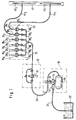
- Figure 1 shows an overall diagram of a device used to quantitatively determine the degree of tightness of a sheet pile assembly.
- a water pressurization group 10 which comprises a pump 12 provided with a drive motor 14, a pressurization tank 16, a pressure switch 18 for switching on the pump 12.
- This group pressurizing valve 10 can be purchased commercially as an assembled unit, either with an electric motor or with a combustion engine. The use of a combustion engine is particularly advantageous on a site.
- the pressurizing group 10 is connected by a suction pipe 20 to a water tank 22. It is however also possible to connect the pressurizing group 10 directly to a water distribution pipe.
- a discharge line 24 connects the pressurizing group 10 to a distributor 26 provided with several outlets 281, 282, 283, ... for measuring circuits.
- a pressure regulator 32 is installed, which reduces the pressure supplied by the pressurizing unit 10 to a determined value. This value can be read on a pressure gauge 34. If there is however a water distribution pipe which has a sufficient supply pressure, it is however also possible to connect the pressure regulator 32 directly to said distribution pipe of water. For each departure 281, 282, 283, ...
- the distributor 26 includes a conventional water meter 361, 362, 363, ..., which is for example of the type where the flow of water turns a turbine which drives needles via toothed wheels indicating the water consumption in l or m3.
- a conventional water meter 361, 362, 363, ... is for example of the type where the flow of water turns a turbine which drives needles via toothed wheels indicating the water consumption in l or m3.
- an isolation valve 381, 382, 383, ... which makes it possible to isolate outgoing circuits (283 - 286) from the distributor which are not connected to a pressurizing body 40 of a joint.
- the reference 40 marks a schematic representation of such a pressurizing body.
- said body 40 comprises two measurement sectors 421, 422 which are respectively connected to a first water meter 361 by a first pipe 441, and to a second water meter 362 by a second pipe 442.
- This body 40 for pressurizing a joint and mounting it on sheet piles will be studied with the aid of FIGS. 2, 3 and 4.
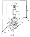
- Figures 2 and 6 show a cross section made at a joint 50 between two sheet piles 52, 54.
- This joint 50 is formed by a claw 56 secured to the first sheet pile 52 which engages with a claw 58 secured to the second sheet pile 54.
- the body 40, respectively 140 for pressurizing the joint in cross section bearing on the two sheet piles 52 and 54.
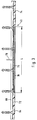
- Figure 3 shows a longitudinal section through the body 40 for pressurizing the joint of Figure 2, this time without the sheet piles.
- it is an oblong body, which has substantially the shape of a prismatic bar. It comprises a metal profile 60 having a "U" section, on the outer face of the core 62 from which is fixed, for example by gluing, an elastomer body 64.
- This elastomer body which extends over the entire length of the profile 60, has a rectangular cross section.
- the free longitudinal edges are however chamfered to form two bearing surfaces 66 and 68. Between these two bearing surfaces 66, 68 the elastomer body 64 is provided with a groove 70 over a length L. This groove 70 is centered by relative to the total length of said elastomer body 64, that is to say that there remains at each end of the elastomer body a sector 72, 74 devoid of groove (see Figure 3).
- said elastomer body will naturally have to be adapted to the shape of the claws respectively to the section of the sheet piles. It follows that said elastomeric body need not necessarily have a section as described above by way of example only.
- this groove 70 is preferably housed a tube 76 for axial water distribution.
- This tube 76 is provided in the middle with a connection sleeve 78 to which a distribution pipe 44 i is connected.
- the purpose of this tube 76 is to axially balance the distribution of water in the groove 70.
- the tube is provided with perforations 80 along a generator.
- Figure 2 shows how this body 40 for pressurizing the joint is mounted on the two sheet piles to define a sealed chamber 82 above a length L of the joint.
- the first bearing surface 66 is supported on the first sheet pile 52 along parallel said seal 50.
- the second bearing surface 68 is supported on the second sheet pile 54 along parallel said seal 50.
- the elastomer body 64 is accordingly located astride above said joint 50.
- props 84 with adjustable length press said elastomer body 64 firmly against the two sheet piles 52, 54, so that the bearing surfaces 66, 68 of the elastomer body 64 provide a longitudinal seal between the latter and the two sheet piles 52, 54.
- the props 84 are supported with one end on stirrups 85 which are welded astride the first sheet pile 52 and the second sheet pile 54, and with the other end on the "U" profile 60 between the two flanges of the last. It has been shown that in practice it most often suffices to provide three of these props 84 per running meter of the body 40 for pressurizing the joint.
- These props 84 with adjustable length preferably comprise a tensioning nut 86 in the first end of which is screwed a threaded rod 88 provided with a straight thread and in the second end of which is screwed a threaded rod 90 provided with a left thread.
- the free ends of these threaded rods are provided with heads 92, 94 each comprising a bearing surface in which is made perpendicular to the axis of the prop a groove 96, 98 which cooperates with the stirrup 85, respectively with a part 99 welded longitudinally on the "U" profile, to avoid rotation or lateral sliding of these heads 92, 94 when the tensioning nut 86 is turned to press the body 40 for pressurizing the joint firmly against the sheet piles 52, 54.
- the lateral tightness between said body 40 for pressurizing the joint and the two sheet piles 52, 54 is therefore guaranteed by pressing the two bearing surfaces 66, 68 of the elastomer body firmly against the two sheet piles.
- the tensioning nut 86 is preferably tightened using a torque wrench, so as to be able to control the contact pressure between the bearing surfaces 66, 68 and the sheet piles 52, 54.
- the axial sealing problem is solved by injecting a sealing mass in the seal 50 between the two claws 56, 58.
- a sealing mass in the seal 50 between the two claws 56, 58.
- the shutter mass used is advantageously a water-swellable mass, that is to say one whose volume increases under the effect of humidity.
- FIG. 4 shows a tubular support structure on which the props 84 come to bear.
- This tubular support structure 100 is intended to be embedded between two opposite surfaces 102, 104 of a sheet pile 106 having a "U" section. It comprises several parallel tubes 108 which are fitted like the steps of a ladder, in the "U" section of the sheet pile 106. To this end each of these tubes 108 or parallel steps is provided at its two ends with a tip 110, 112 made of hardened steel. At least one of these points 110 is each supported axially by a threaded rod 114 which is screwed into the tube 108. Said steps 108 support a tube 116 which is approximately parallel to the joint and which stands at a certain distance from that -this. On this tube 116 bear the props 84 with one of their heads 92, 94 to press the body 40 for pressurizing the joint against the two sheet piles.
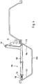
- Figure 5 shows an overall diagram of another advantageous embodiment of the device which makes it possible to measure very small leaks through joints in a sheet pile assembly.
- a calibrated piston 210 which allows flow measurements up to approximately 0.1 cm3 / 24 h, is filled with water and a constant pressure P is applied.
- the piston 210 is connected to a pressurizing body 40 located astride a joint 50 by means of a conduit 212.
- the water supply to the body 40 can be interrupted by means of a valve 214 placed in the conduit 212.
- the body 40 is equipped with a pressure sensor 216 which is connected to a pressure indicator 218 and to a recorder 220.
- the pressure indicator 218 and the recorder 220 allow direct reading respectively a recording, in diagram form, pressure drops resulting from leaks through the joint 40 of a sheet pile.
- the body 40 can also be equipped with a conventional pressure gauge 222 allowing the analogous reading of the instantaneous pressure in the body 40.
- the body 40 is also equipped with a valve 224 which makes it possible to purge and drain the system.
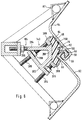
- Figure 6 shows another preferred embodiment of a pressurizing body 140.
- This preferred embodiment is specially adapted for measuring relatively low leakage rates.
- the shape and tightness of the elastomer body 64 as well as the compression system of the elastomer body against the sheet piling have been adapted to meet the more stringent requirements imposed by the low leakage rates to be measured.
- the struts 84 of the device of FIG. 2 have also been adapted so as to guarantee that a pressure exerted on the elastomer body 64 is distributed uniformly over the two bearing surfaces.
- the props 84 of Figure 2 have been replaced by one or more fixing systems 184 which each include a main compression screw 284 and two secondary compression screws 384, 385.
- the screws 284, 384, 385 are supported with one end on stirrups 85 which are fixed to the sheet piles 52, 54 by means of fixings 87 integral with the sheet piles 52, 54.
- the other end of the main screw 284 forms a flange 288 bearing on the elastomer body 64.
- the other end of the first secondary compression screw 384 and the second secondary compression screw each form a secondary sole 388, 389 resting on the longitudinal edges of the elastomer body 64.
- the central sole 288 connects the two main compression screws 284 by means of a T-shaped profile 392.
- the three screws 284, 384, 385 comprise a threaded rod and a tensioning nut 295, 395, 396. By tightening the tensioning nuts 295, 395, 396, the elastomer body 64 is pressed firmly against the two sheet piles 52, 54.
- the three screws 284, 384, 385 thus exert pressure on the central flange 288 while the two secondary screws 384, 385 in addition exert a pressure which is distributed over the longitudinal edges of the elastomer body 64 via the secondary soles 388, 389. It is important to note that the central sole 288 is not directly connected to the two lateral soles 388, 389 . It is thus ensured that the lateral edges of the elastomer body 64 do not deviate from the sheet piles 52, 54 when a strong pressure is exerted on the central flange. This results in a better seal between the elastomer body 64 and the sheet piles 52, 54.
- the present invention describes a method for quantitatively determining, in a simple and perfectly reproducible manner, the degree of tightness of a sheet pile assembly, both on site and in the workshop.
- the device for implementing this process is simple to use and is particularly suitable for the harsh conditions to which it is subjected on the site.
Landscapes
- Physics & Mathematics (AREA)
- General Physics & Mathematics (AREA)
- Bulkheads Adapted To Foundation Construction (AREA)
- Examining Or Testing Airtightness (AREA)
Applications Claiming Priority (4)
| Application Number | Priority Date | Filing Date | Title |
|---|---|---|---|
| LU88134 | 1992-06-17 | ||
| LU88134A LU88134A1 (fr) | 1992-06-17 | 1992-06-17 | Procede et dispositif pour determiner quantitativement le degre d'etancheite d'un assemblage de palplanches |
| LU88254 | 1993-05-05 | ||
| LU88254A LU88254A1 (fr) | 1993-05-05 | 1993-05-05 | Procede et dispositif pour determiner quantitativement le degre d'etancheite d'un assemblage de palplanches |
Publications (3)
| Publication Number | Publication Date |
|---|---|
| EP0574773A2 true EP0574773A2 (de) | 1993-12-22 |
| EP0574773A3 EP0574773A3 (de) | 1994-02-16 |
| EP0574773B1 EP0574773B1 (de) | 1997-01-08 |
Family
ID=26640345
Family Applications (1)
| Application Number | Title | Priority Date | Filing Date |
|---|---|---|---|
| EP19930108992 Expired - Lifetime EP0574773B1 (de) | 1992-06-17 | 1993-06-04 | Verfahren und Vorrichtung für die quantitative Bestimmung der Dichtigkeit eines Spundbohlenaufbaus |
Country Status (4)
| Country | Link |
|---|---|
| EP (1) | EP0574773B1 (de) |
| DE (1) | DE69307193T2 (de) |
| DK (1) | DK0574773T3 (de) |
| ES (1) | ES2097945T3 (de) |
Family Cites Families (1)
| Publication number | Priority date | Publication date | Assignee | Title |
|---|---|---|---|---|
| JPS5313423Y2 (de) * | 1972-09-21 | 1978-04-11 |
-
1993
- 1993-06-04 EP EP19930108992 patent/EP0574773B1/de not_active Expired - Lifetime
- 1993-06-04 DK DK93108992T patent/DK0574773T3/da active
- 1993-06-04 DE DE1993607193 patent/DE69307193T2/de not_active Expired - Lifetime
- 1993-06-04 ES ES93108992T patent/ES2097945T3/es not_active Expired - Lifetime
Also Published As
| Publication number | Publication date |
|---|---|
| DE69307193T2 (de) | 1997-06-26 |
| ES2097945T3 (es) | 1997-04-16 |
| DE69307193D1 (de) | 1997-02-20 |
| EP0574773A3 (de) | 1994-02-16 |
| DK0574773T3 (da) | 1997-06-30 |
| EP0574773B1 (de) | 1997-01-08 |
Similar Documents
| Publication | Publication Date | Title |
|---|---|---|
| FR2552230A1 (fr) | Procede et appareil de detection de parametres physiques d'une canalisation, notamment pour l'indication de troncons non supportes | |
| EP0574773B1 (de) | Verfahren und Vorrichtung für die quantitative Bestimmung der Dichtigkeit eines Spundbohlenaufbaus | |
| EP0032648A1 (de) | Statische Penetrometervorrichtung | |
| FR2528522A1 (fr) | Soupape de decompression de securite | |
| LU88254A1 (fr) | Procede et dispositif pour determiner quantitativement le degre d'etancheite d'un assemblage de palplanches | |
| LU88134A1 (fr) | Procede et dispositif pour determiner quantitativement le degre d'etancheite d'un assemblage de palplanches | |
| CH463821A (fr) | Procédé et appareil pour déterminer la pression interstitielle du sol | |
| FR2708347A1 (fr) | Chambre de mesure, notamment pour le contrôle de l'eau d'une piscine. | |
| CA2959939A1 (fr) | Couplemetre hydraulique | |
| EP0720006A1 (de) | Verfahren und Vorrichtung zur nicht intrusiven Messung der Druckschwankungen einer Flüssigkeit innerhalb einer Kanalisation | |
| FR2500623A1 (fr) | Debitmetre a vortex a detection exterieure | |
| EP0705941B1 (de) | Pressiometer mit zwei Piezometer | |
| FR2586808A1 (fr) | Procede et dispositif pour la detection et la localisation de fuites au niveau des parois d'un bassin tel qu'une piscine de desactivation de centrale nucleaire | |
| FR2509008A1 (fr) | Joint elastique etanche notamment pour dispositif de commande du debit d'un fluide | |
| FR2576415A1 (fr) | Appareil de mesure de la permeabilite de terrains et plus particulierement de formations tres faiblement permeables, du type a test impulsionnel | |
| FR2466695A1 (fr) | Systeme de controle des conditions de forage d'un sondage horizontal et dispositif d'etancheite pour ce systeme | |
| JP2003056286A (ja) | 裏込注入圧計測装置 | |
| FR2941975A1 (fr) | Dispositif permettant de mettre en pression une partie de la paroi d'un puits | |
| FR2482302A1 (fr) | Viscosimetre a mesure continue | |
| JPH0660860B2 (ja) | 開水路継目部の漏水検査装置 | |
| CA2345820C (en) | Differential pressure gauge assembly | |
| KR100958384B1 (ko) | 유압을 이용한 관로 수밀 검사 시스템 및 sod 공법 | |
| FR3019296A1 (fr) | Machine d'essai pour appliquer une pression interne a un tube de petit diametre | |
| FR2649753A1 (fr) | Procede d'essai de forage | |
| JP2006241861A (ja) | 河川構造物のゲート開閉操作方法およびその装置 |
Legal Events
| Date | Code | Title | Description |
|---|---|---|---|
| PUAI | Public reference made under article 153(3) epc to a published international application that has entered the european phase |
Free format text: ORIGINAL CODE: 0009012 |
|
| AK | Designated contracting states |
Kind code of ref document: A2 Designated state(s): BE CH DE DK ES FR IT LI NL SE |
|
| PUAL | Search report despatched |
Free format text: ORIGINAL CODE: 0009013 |
|
| AK | Designated contracting states |
Kind code of ref document: A3 Designated state(s): BE CH DE DK ES FR IT LI NL SE |
|
| 17P | Request for examination filed |
Effective date: 19940623 |
|
| GRAG | Despatch of communication of intention to grant |
Free format text: ORIGINAL CODE: EPIDOS AGRA |
|
| 17Q | First examination report despatched |
Effective date: 19960328 |
|
| GRAH | Despatch of communication of intention to grant a patent |
Free format text: ORIGINAL CODE: EPIDOS IGRA |
|
| GRAH | Despatch of communication of intention to grant a patent |
Free format text: ORIGINAL CODE: EPIDOS IGRA |
|
| GRAA | (expected) grant |
Free format text: ORIGINAL CODE: 0009210 |
|
| AK | Designated contracting states |
Kind code of ref document: B1 Designated state(s): BE CH DE DK ES FR IT LI NL SE |
|
| REG | Reference to a national code |
Ref country code: CH Ref legal event code: EP |
|
| REF | Corresponds to: |
Ref document number: 69307193 Country of ref document: DE Date of ref document: 19970220 |
|
| ITF | It: translation for a ep patent filed | ||
| REG | Reference to a national code |
Ref country code: CH Ref legal event code: NV Representative=s name: MICHELI & CIE INGENIEURS-CONSEILS |
|
| REG | Reference to a national code |
Ref country code: ES Ref legal event code: FG2A Ref document number: 2097945 Country of ref document: ES Kind code of ref document: T3 |
|
| REG | Reference to a national code |
Ref country code: DK Ref legal event code: T3 |
|
| PLBE | No opposition filed within time limit |
Free format text: ORIGINAL CODE: 0009261 |
|
| STAA | Information on the status of an ep patent application or granted ep patent |
Free format text: STATUS: NO OPPOSITION FILED WITHIN TIME LIMIT |
|
| 26N | No opposition filed | ||
| REG | Reference to a national code |
Ref country code: CH Ref legal event code: PUE Owner name: ARCELOR PROFIL LUXEMBOURG SA Free format text: ARCELOR LUXEMBOURG S.A.#AVENUE DE LA LIBERTE 19#2930 LUXEMBOURG (LU) -TRANSFER TO- ARCELOR PROFIL LUXEMBOURG SA#AVENUE DE LA LIBERTE 19#2930 LUXEMBOURG (LU) Ref country code: CH Ref legal event code: PFA Owner name: ARCELOR LUXEMBOURG S.A. Free format text: ARBED S.A.#AVENUE DE LA LIBERTE 19#L-2930 LUXEMBOURG (LU) -TRANSFER TO- ARCELOR LUXEMBOURG S.A.#AVENUE DE LA LIBERTE 19#2930 LUXEMBOURG (LU) |
|
| NLS | Nl: assignments of ep-patents |
Owner name: ARCELOR PROFIL LUXEMBOURG S.A. Effective date: 20070115 |
|
| NLT1 | Nl: modifications of names registered in virtue of documents presented to the patent office pursuant to art. 16 a, paragraph 1 |
Owner name: ARCELOR LUXEMBOURG S.A. |
|
| REG | Reference to a national code |
Ref country code: FR Ref legal event code: TP Ref country code: FR Ref legal event code: CD |
|
| REG | Reference to a national code |
Ref country code: ES Ref legal event code: PC2A |
|
| BECH | Be: change of holder |
Owner name: S.A. *ARCELOR PROFIL LUXEMBOURG Effective date: 20061213 |
|
| REG | Reference to a national code |
Ref country code: CH Ref legal event code: PFA Owner name: ARCELORMITTAL BELVAL & DIFFERDANGE Free format text: ARCELOR PROFIL LUXEMBOURG SA#AVENUE DE LA LIBERTE 19#2930 LUXEMBOURG (LU) -TRANSFER TO- ARCELORMITTAL BELVAL & DIFFERDANGE#66, ROUTE DE LUXEMBOURG#4221 ESCH SUR ALZETTE (LU) |
|
| REG | Reference to a national code |
Ref country code: ES Ref legal event code: PC2A |
|
| REG | Reference to a national code |
Ref country code: FR Ref legal event code: CD |
|
| PGFP | Annual fee paid to national office [announced via postgrant information from national office to epo] |
Ref country code: SE Payment date: 20110629 Year of fee payment: 19 Ref country code: CH Payment date: 20110516 Year of fee payment: 19 Ref country code: FR Payment date: 20110523 Year of fee payment: 19 Ref country code: ES Payment date: 20110519 Year of fee payment: 19 |
|
| PGFP | Annual fee paid to national office [announced via postgrant information from national office to epo] |
Ref country code: NL Payment date: 20110526 Year of fee payment: 19 Ref country code: BE Payment date: 20110516 Year of fee payment: 19 Ref country code: DK Payment date: 20110627 Year of fee payment: 19 |
|
| PGFP | Annual fee paid to national office [announced via postgrant information from national office to epo] |
Ref country code: DE Payment date: 20110516 Year of fee payment: 19 Ref country code: IT Payment date: 20110624 Year of fee payment: 19 |
|
| REG | Reference to a national code |
Ref country code: DE Ref legal event code: R082 Ref document number: 69307193 Country of ref document: DE Representative=s name: PATENTANWALTSKANZLEI VIEL & WIESKE, DE |
|
| BERE | Be: lapsed |
Owner name: ARCELORMITTAL BELVAL 1 DIFFERDANGE Effective date: 20120630 |
|
| REG | Reference to a national code |
Ref country code: NL Ref legal event code: V1 Effective date: 20130101 |
|
| REG | Reference to a national code |
Ref country code: DK Ref legal event code: EBP |
|
| REG | Reference to a national code |
Ref country code: SE Ref legal event code: EUG |
|
| REG | Reference to a national code |
Ref country code: CH Ref legal event code: PL |
|
| REG | Reference to a national code |
Ref country code: CH Ref legal event code: PL |
|
| PG25 | Lapsed in a contracting state [announced via postgrant information from national office to epo] |
Ref country code: IT Free format text: LAPSE BECAUSE OF NON-PAYMENT OF DUE FEES Effective date: 20120604 Ref country code: SE Free format text: LAPSE BECAUSE OF NON-PAYMENT OF DUE FEES Effective date: 20120605 |
|
| REG | Reference to a national code |
Ref country code: FR Ref legal event code: ST Effective date: 20130228 |
|
| REG | Reference to a national code |
Ref country code: DE Ref legal event code: R119 Ref document number: 69307193 Country of ref document: DE Effective date: 20130101 |
|
| PG25 | Lapsed in a contracting state [announced via postgrant information from national office to epo] |
Ref country code: NL Free format text: LAPSE BECAUSE OF NON-PAYMENT OF DUE FEES Effective date: 20130101 Ref country code: DE Free format text: LAPSE BECAUSE OF NON-PAYMENT OF DUE FEES Effective date: 20130101 Ref country code: BE Free format text: LAPSE BECAUSE OF NON-PAYMENT OF DUE FEES Effective date: 20120630 Ref country code: FR Free format text: LAPSE BECAUSE OF NON-PAYMENT OF DUE FEES Effective date: 20120702 Ref country code: LI Free format text: LAPSE BECAUSE OF NON-PAYMENT OF DUE FEES Effective date: 20120630 Ref country code: CH Free format text: LAPSE BECAUSE OF NON-PAYMENT OF DUE FEES Effective date: 20120630 |
|
| PG25 | Lapsed in a contracting state [announced via postgrant information from national office to epo] |
Ref country code: DK Free format text: LAPSE BECAUSE OF NON-PAYMENT OF DUE FEES Effective date: 20120702 |
|
| REG | Reference to a national code |
Ref country code: ES Ref legal event code: FD2A Effective date: 20131021 |
|
| PG25 | Lapsed in a contracting state [announced via postgrant information from national office to epo] |
Ref country code: ES Free format text: LAPSE BECAUSE OF NON-PAYMENT OF DUE FEES Effective date: 20120605 |