EP0574818B1 - Brandschutzverglasung - Google Patents
Brandschutzverglasung Download PDFInfo
- Publication number
- EP0574818B1 EP0574818B1 EP93109268A EP93109268A EP0574818B1 EP 0574818 B1 EP0574818 B1 EP 0574818B1 EP 93109268 A EP93109268 A EP 93109268A EP 93109268 A EP93109268 A EP 93109268A EP 0574818 B1 EP0574818 B1 EP 0574818B1
- Authority
- EP
- European Patent Office
- Prior art keywords
- glass
- pane
- pressure medium
- limb
- fire
- Prior art date
- Legal status (The legal status is an assumption and is not a legal conclusion. Google has not performed a legal analysis and makes no representation as to the accuracy of the status listed.)
- Expired - Lifetime
Links
Images


Classifications
-
- E—FIXED CONSTRUCTIONS
- E06—DOORS, WINDOWS, SHUTTERS, OR ROLLER BLINDS IN GENERAL; LADDERS
- E06B—FIXED OR MOVABLE CLOSURES FOR OPENINGS IN BUILDINGS, VEHICLES, FENCES OR LIKE ENCLOSURES IN GENERAL, e.g. DOORS, WINDOWS, BLINDS, GATES
- E06B5/00—Doors, windows, or like closures for special purposes; Border constructions therefor
- E06B5/10—Doors, windows, or like closures for special purposes; Border constructions therefor for protection against air-raid or other war-like action; for other protective purposes
- E06B5/16—Fireproof doors or similar closures; Adaptations of fixed constructions therefor
- E06B5/165—Fireproof windows
Definitions
- the invention relates to fire protection glazing with a frame or facade profiles acting as a frame with a fold optionally formed by glass retaining strips, in which at least one pane with associated seals and / or covering strips made of organic or inorganic material is installed, at least on the side facing the fire
- a shading device is provided in the area of the rebate, which can be activated and moved in the event of a fire independently of a window pressure and which completely pushes in front of the area of the window to be shaded when a predetermined temperature is exceeded.
- the laminated glass which is also used in fire protection glazing, breaks, but is replaced by a wire insert or an intermediate layer, e.g. made of alkali silicate or water-containing gels, and can still fulfill their fire protection function. However, they also soften and can then slip out of the frame.
- the fire protection function can only be fulfilled if the aforementioned panes are held securely in the frame.
- fire protection glazing was therefore developed, whose frame systems prevent the panes from slipping out of the frame.
- DE-OS 34 23 298, DE-OS 34 36 236 and DE-OS 36 21 943 known to generate an additional contact pressure only in the event of fire by using springs or intumescent materials activated by heat, which are used between the pane and frame are arranged.
- Springs have the disadvantage already described above that they can burn out.
- Intumescent materials are inexpensive and easy to use. They foam up with the formation of gas, but the gases which produce the pressure tend to evaporate, so that the contact pressure drops again after a short time or is even completely ineffective.
- a shading device is known from GB-A-2171136, which consists of intumescent material.
- intumescent material In the event of a fire, the material swells and pushes in front of the edge of the pane without exerting pressure on the pane.
- the disadvantage is that a lot of material is required to shade a correspondingly large edge area.
- a hard intumescent material is therefore used, in which an attempt is made to direct the expansion of the material in one direction only by means of laminar construction and the incorporation of reinforcing fibers or wire mesh.
- such laminates are expensive to manufacture and their effect is not reliable.
- the object of the invention is therefore to provide fire protection glazing which is simple and inexpensive to manufacture and assemble, and with which a predetermined edge region of the pane is reliably protected against the effects of heat only in the event of a fire.
- the shading device has two components, namely a slide and a pressure medium which expands under the action of heat and acts on the slide.
- the shading device according to the invention of the pane has the advantage that it can be activated and moved in the event of a fire independently of a pane pressure. This means that shading and contact pressure on the pane are decoupled and do not influence each other. This decoupling also has the advantage that the shading device immediately fulfills its full protective effect for the edge region when a predetermined temperature is exceeded and thereby keeps the edge of the pane cool over a long period of time.
- the pane is an inexpensive part of the sheet that is moved in front of the pane edge in the event of a fire and remains there, thus reliably shading the pane edge in a simple manner.
- Permanent shading for example due to a high edge protrusion, would have disadvantages, particularly for toughened soda-lime glasses.
- a high edge incidence in the heating phase of the fire causes too high a thermally induced voltage due to the temperature difference and thus a high risk of breakage of the soda-lime glass.
- toughened soda-lime glasses are only installed in fire protection glazing with a small edge gap of approx. 10 mm. Since, according to the invention, the shading device is not yet active in the heating phase of a fire but only when a predetermined temperature is exceeded, the shading device according to the invention is preferably used in soda-lime glasses.
- the shading is primarily to be arranged on the side of the window facing the fire, since an arrangement on the side facing away from the fire may be necessary. can have a shortening effect on the fire resistance time.
- the extended service life of the shading is due to a wide, cool edge of the pane, which does not soften as quickly and keeps the pane stable over a long period of time.
- the shading device can also be used not only for soda-lime glasses but also for wire glass or laminated glasses to extend their service life. If such panes are not protected from the fire chamber radiation, they heat up considerably in the course of the fire and soften accordingly. The softened pane slumps in itself, slips out of the fold, so that the fire protection effect is no longer guaranteed.
- the shading can effectively delay this process by the wide, cool edge of the pane maintaining the softened central surface of the glass and the pane accordingly slumping later. The time saved in these applications can be up to 15 minutes.
- the slide consists of an angle profile element, preferably an angle plate, which, together with the pressure medium, is accommodated in an intermediate space between the pane and the frame part or the glass retaining strip.
- the angle profile element lies on the pressure medium and covers the free surface of the pressure medium with its first leg.
- the second leg is aligned parallel to the disc and arranged in front of it.
- the dimensions of the angle profile element are chosen so that the angle profile element together with the pressure medium completely in the space between the disc or the sealing element of the disc and the frame part or glass holding bar is housed and does not protrude from the frame part or glass holding bar.
- a limiting flange is provided on the frame part or glass retaining strip, which covers the intermediate space except for a gap for the passage of the second leg of the angle profile element.
- the angle profile element is guided with its second leg between this limiting flange and the glass pane or a sealing element assigned to the pane.
- the limiting flange serves as a stop for the first leg when the angle profile element is completely extended to cover the desired edge area.
- the slide is designed as a rectangular profile, which is accommodated together with the pressure medium between the pane or a sealing element of the pane and the frame part or the glass retaining strip, the rectangular profile covering the free surface of the pressure medium similar to the angle profile element.
- the dimensions of the rectangular profile are such that it is essentially flush with the frame part or the glass retaining strip.
- an angle bar formed from two legs.
- This angle bar partially encompasses the glass holding bar and is attached with its first leg to the frame part or the glass holding bar.
- the second leg is essentially perpendicular to the disc and extends from the first leg towards the disc.
- the second leg is spaced from the frame part or the glass retaining strip, so that an intermediate space is created in which the pressure medium is accommodated.
- the second leg preferably extends close to the glass pane. If the pressure medium expands in the event of a fire, the second leg is bent up or raised under the pressure that occurs. The second leg remains in its end position after the expansion of the pressure medium. The bent second leg also prevents premature release of the pressure medium.
- pressure mediums which expand, foam or inflate under the action of heat can be used as pressure mediums.
- Pyrolytic materials, intumescent material, expandable graphite, vermiculite, zeolite, pearlite, mica or borax are preferred.
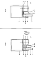
- Figures 1 and 2 show a frame made of a stop profile 4, with the associated stop 5, against which the glass pane 1 rests with its sealing strip 2b.
- a sealing strip 2a is also provided on the opposite side of the glass pane 1.
- the glass pane 1 rests on the stop profile 4 with a block 3.
- a glass holding strip 6 is mounted on the stop profile 4, so that an intermediate space 8 is formed between the glass holding strip 6 and the pane 1 or the sealing strip 2a, in which the shading device 10 is accommodated.
- This shading device 10 consists of the pressure medium resting on the stop profile 4 in the form of intumescent material 11 and an angle profile element 13 resting on this pressure medium 11 and forming the slide 12.
- the first leg 14 of the angle profile element 13 covers the free surface of the intumescent material 11 during the second leg 15 is erected parallel to the disc 1 and abuts the sealing strip 2a. This prevents that when the intumescent material expands under the influence of heat, it can escape without exerting pressure on the slide 12.
- the length of the second leg 15 is chosen so that it does not protrude upwards relative to the glass retaining strip 6.
- a gap 16 is left free between the limiting flange 7 and the sealing strip 2a, through which the second leg 15 can pass.
- the angle profile element 13 is formed by the expansion of the Pushed pressure medium 11 so far up that the first leg 14 rests with its upper side on the underside of the limiting flange 7.
- the end position of the slide 12 is reached and this covers with its second leg 15 the predetermined edge area 24 of the disc 1, so that it is protected from the effects of fire and kept cool for a certain time.
- the gap 16 is formed in such a way that the angle profile element 13 is guided without jamming when pushed up.
- FIGS. 3 and 4 A further embodiment is shown in FIGS. 3 and 4.
- a pressure medium 11 in the form of an intumescent material is also provided in the space 8 on the stop profile 4.
- the slider in this embodiment consists of a rectangular profile 17 which completely fills the remaining free space of the intermediate space 8 and is essentially flush with the upper edge of the glass holding strip 6. Characterized in that the rectangular profile 17 fills the space 8, this is guided between the sealing strip 2a and the glass retaining strip 6 when the pressure medium 11 is expanded. This is shown in FIG. 4. After the intumescent material 11 has expanded to the maximum, the slide 12 has reached its end position and effectively shades the predetermined edge area 24 of the glass pane 1.
- FIGS. Another embodiment is shown in FIGS.
- the space between the sealing strip 2a and the glass retaining strip 6 has been omitted in this embodiment. Instead is the intumescent material applied to the glass holding bar 6 and is covered by an angle bar 18.
- the first leg 19 of the angle bar 18 is attached to a side wall of the glass retaining bar 6.
- the second leg 20, which extends perpendicular to the glass pane 1 up to close to the glass pane 1, is arranged at a distance from the glass holding strip 6, so that the pressure medium 11 is completely enclosed in the intermediate space formed thereby.
- the sealing strip 2a is preferably pulled up so far that the second leg 20 rests on the sealing strip 2a, so that the intermediate space 21 is closed on all sides.
- the pressure medium 11 expands and in doing so bends the second leg upwards.
- the fact that the second leg 20 extends close to the glass pane 1 prevents undesired escape in the case of intumescent material between the leg 20 and the glass pane 1.
- corresponding precautions are taken at the junction of the two legs 19 and 20. After the pressure medium 11 has reached its maximum extent, the second leg 20 remains in its end position and thus covers the predetermined edge area 24.
Landscapes
- Engineering & Computer Science (AREA)
- Civil Engineering (AREA)
- Structural Engineering (AREA)
- Joining Of Glass To Other Materials (AREA)
- Special Wing (AREA)
- Glass Compositions (AREA)
- Securing Of Glass Panes Or The Like (AREA)
- Window Of Vehicle (AREA)
- Ceramic Products (AREA)
- Inorganic Insulating Materials (AREA)
- Aiming, Guidance, Guns With A Light Source, Armor, Camouflage, And Targets (AREA)
Description
- Die Erfindung betrifft eine Brandschutzverglasung mit einem Rahmen oder als Rahmen wirkenden Fassadenprofilen mit einem gegebenenfalls durch Glashalteleisten gebildeteten Falz, in welchem wenigstens eine Scheibe mit zugehörigen Dichtungen und/oder Vorlegebändern aus organischem oder anorganischem Material eingebaut ist, wobei Zumindest auf der feuer zu gewandten Seite der Scheibe im Bereich des Falzes eine Abschattungseinrichtung vorgesehen ist, die im Brandfall unabhängig von einer Scheibenpressung aktivierbar und bewegbar ist und die sich bei Überschreiten einer vorgegebenen Temperatur vollständig vor den abzuschattenden Bereich der Scheibe schiebt.
- Herkömmliche, in Brandschutzverglasungen eingesetzte Spezialglasscheiben, z.B. vorgespannte Borosilikatgläser, zerbrechen im Falle eines Brandes nicht, sondern werden weich und können infolge ihres Gewichtes als verformte Masse aus der Halterung oder dem Rahmen rutschen.
- Die ebenfalls in Brandschutzverglasungen eingesetzten Verbundgläser zerbrechen zwar, werden jedoch durch eine Drahteinlage oder eine Zwischenschicht, z.B. aus Alkalisilikat oder wasserhaltigen Gelen, zusammengehalten und können dadurch ihre Brandschutzfunktion noch erfüllen. Sie erweichen jedoch ebenfalls und können dann aus dem Rahmen rutschen. Die Brandschutzfunktion kann aber nur dann erfüllt werden, wenn die vorgenannten Scheiben sicher im Rahmen gehalten werden.
- Um hier Abhilfe zu schaffen und höhere Feuerwiderstandszeiten zu erreichen, wurden daher Brandschutzverglasungen entwickelt, deren Rahmensysteme das Herausrutschen der Scheiben aus dem Rahmen verhindern.
- Aus der DE-OS 38 26 260 ist es bekannt, die Ränder der Scheiben mittels Klemmleisten, die unter Federvorspannung stehen, einzuspannen. Die Federvorspannung wird durch Blatt-, Teller- oder Schraubenfedern erzeugt. Diese Konstruktion ist verhältnismäßig aufwendig, muß sehr sorgfältig montiert werden, um Glasbruch zu verhindern und die gewünschte Brandschutzfunktion zu erzielen, und besitzt darüber hinaus den Nachteil, daß Federn unter dem Einfluß von Hitze ihre Spannkraft verlieren können, indem sie ausglühen. Dadurch geht die Federwirkung verloren.
- Es ist auch z.B. aus der DE-OS 34 23 298, der DE-OS 34 36 236 und der DE-OS 36 21 943 bekannt, einen zusätzlichen Anpreßdruck erst im Brandfalle zu erzeugen, indem durch Wärme aktivierte Federn oder Intumeszenzmassen verwendet werden, die zwischen Scheibe und Rahmen angeordnet sind. Federn haben den bereits oben beschriebenen Nachteil, daß sie ausglühen können. Intumeszenzmaterialien sind preiswert und einfach in der Anwendung. Sie schäumen unter Gasbildung auf, wobei die den Druck erzeugenden Gase aber die Tendenz haben, sich zu verflüchtigen, so daß der Anpreßdruck bereits nach kurzer Zeit wieder nachläßt oder sogar vollkommen unwirksam wird.
- Aus der DE-PS 39 39 149 ist eine Brandschutzverglasung bekannt, bei der die Einspannmittel als bewegliche Keile ausgebildet sind. Der Falz ist mit mit den Keilen zusammenwirkenden Anlaufschrägen versehen, durch die bei Ausübung eines Druckes auf die Treibflächen der Keile diese auf die Scheibe gepreßt werden. Als Druckmittel wird eine unter Wärmeeinwirkung sich ausdehnendes oder aufblähbares Material verwendet. Wenn sich die Keile aufgrund der Ausdehnung des Druckmittels längs der Anlaufschrägen bewegen, stehen sie auch gegenüber der Glashalteleiste geringfügig vor. Zwar wird in diesem Zusammenhang eine gewisse Abschattung des Randbereiches der Scheibe erwähnt, jedoch wird diese für einige Glasscheiben als nachteiliger Nebeneffekt angesehen. Da die Anpressung im Randbereich im Vordergrund steht, wird auch keine gezielte Abschattung über einen vorgegebenen Randbereich angestrebt. Nachteilig bei dieser Anordnung ist, daß die Abschattung - falls sie überhaupt eintritt - langsam erfolgt, vom Anpreßdruck abhängig ist und die Keile nur geringfügig ausgefahren werden, so daß eine wirksame Abschattung eines vorgegebenen Randbereiches nicht erzielbar ist.
- Aus der GB-A-2171136 ist eine Abschattungseinrichtung bekannt, die aus Intumeszenzmaterial besteht. Im Brandfall quillt das Material auf und schiebt sich, ohne Druck auf die Scheibe auszuüben, vor den Scheibenrand. Der Nachteil besteht darin, daß sehr viel Material benötigt wird, um einen entsprechend großen Randbereich abzuschatten. Es wird daher ein hartes Intumeszenzmaterial verwendet, bei dem durch laminaren Aufbau und den Einbau von Verstärkungsfasern oder Drahtgewebe versucht wird, die Ausdehnung des Materials nur in eine Richtung zu lenken. Solche Laminate sind jedoch teuer in der Herstellung und ihre Wirkung ist nicht zuverlässig.
- Aufgabe der Erfindung ist es daher, eine Brandschutzverglasung bereitzustellen, die einfach und preiswert herstellbar und montierbar ist, und mit der erst im Brandfalle ein vorgegebener Randbereich der Scheibe Zuverlässig vor Wärmeeinwirkung geschützt wird.
- Diese Aufgabe wird mit einer Brandschutzverglasung gemäß Anspruch 1 gelöst.
- Die Abschattungseinrichtung weist zwei Komponenten auf und zwar einen Schieber und ein sich unter Wärmeeinwirkung ausdehnendes, auf den Schieber einwirkendes Druckmittel.
- Die erfindungsgemäße Abschattungseinrichtung der Scheibe hat den Vorteil, daß sie im Brandfall unabhängig von einer Scheibenpressung aktivierbar und bewegbar ist. Abschattung und Anpressung der Scheibe sind dadurch entkoppelt und beeinflussen sich nicht gegenseitig. Diese Entkopplung bietet weiterhin den Vorteil, daß die Abschattungseinrichtung bei Überschreiten einer vorgegebenen Temperatur sofort ihre volle Schutzwirkung für den Randbereich erfüllt und den Scheibenrand dadurch über längere Zeit kühl hält.
- Der Scheiber ist ein preiswertes Banteil, das im Brandfall vor den Scheibenrand bewegt wird und dort verbleibt und somit auf einfache Weise den Scheibenrand zuverlässig abschattet.
- Eine permanent vorhandene Abschattung, beispielsweise durch einen hohen Randeinstand, würde Nachteile, insbesondere für vorgespannte Kalk-Natron-Gläser mit sich bringen. Ein hoher Randeinstand verursacht in der Aufheizphase des Brandes eine zu hohe thermisch induzierte Spannung aufgrund des Temperaturunterschieds und damit ein großes Bruchrisiko des Kalk-Natron-Glases. Aus diesem Grund werden vorgespannte Kalk-Natron-Gläser nur mit einem geringen Randeinstand von ca. 10 mm in Brandschutzverglasungen eingebaut. Da erfindungsgemäß in der Aufheizphase eines Brandes die Abschattungseinrichtung noch nicht aktiv ist sondern erst bei Überschreiten einer vorgegebenen Temperatur, wird die erfindungsgemäße Abschattungseinrichtung bevorzugt bei Kalk-Natron-Gläsern eingesetzt.
- Die Abschattung ist vornehmlich auf der dem Feuer zugewandten Seite der Scheibe anzuordnen, da eine Anordnung auf der feuerabgekehrten Seite u.U. auf die Feuderwiderstandszeit verkürzend wirken kann. Die Standzeitverlängerung der Abschattung beruht auf einem breiten, kühlen Rand der Scheibe, welche nicht so schnell erweicht und die Scheibe über längere Zeit stabil hält.
- Versuche habe gezeigt, daß mit einer etwa 10 mm breiten Abschattung entlang des Scheibenrandes die Standzeit von vorgespanntem Borosilikatglas in einem Rahmen ohne Anpressung auf über 60 Minuten gegenüber etwa 50 Minuten mit der gleichen Scheibe und ansonsten gleichem Rahmen verlängert werden kann.
- Die Abschattungseinrichtung kann auch nicht nur für Kalk-Natron-Gläser sondern auch für Drahtglas oder Verbundgläser zur Verlängerung ihrer Standzeit eingesetzt werden. Werden solche Scheiben nicht vor der Brandraumstrahlung geschützt, erwärmen sie sich im Verlauf des Brandes stark und erweichen dementsprechend. Die so erweichte Scheibe sackt in sich zusammen, rutscht aus dem Falz heraus, so daß die Brandschutzwirkung nicht mehr gewährleistet ist. Die Abschattung kann diesen Prozeß wirkungsvoll verzögern, indem der breite, kühle Rand der Scheibe die erweichte Mittelfäche des Glases aufrechterhält und die Scheibe sackt dementsprechend später zusammen. Der Zeitgewinn kann in diesen Anwendungsfällen bis zu 15 Minuten betragen.
- Gemäß einer ersten Ausführungsform besteht der Schieber aus einem Winkelprofilelement, vorzugsweise einem Winkelblech, das zusammen mit dem Druckmittel in einem Zwischenraum zwischen der Scheibe und dem Rahmenteil bzw. der Glashalteleiste untergebracht ist. Das Winkelprofilelement liegt auf dem Druckmittel auf und deckt mit seinem ersten Schenkel die freie Oberfläche des Druckmittels ab. Der zweite Schenkel ist parallel zu Scheibe ausgerichtet und vor dieser angeordnet. Die Abmessungen des Winkelprofilelementes sind so gewählt, daß das Winkelprofilelement zusammen mit dem Druckmittel vollständig in dem Zwischenraum zwischen der Scheibe bzw. dem Dichtelement der Scheibe und dem Rahmenteil bzw. Glashalteleiste untergebracht ist und nicht gegenüber dem Rahmenteil bzw. Glashalteleiste vorsteht.
- Um das Winkelprofilelement bei Ausdehnung des Druckmittels im Brandfall zu führen, ist an dem Rahmenteil bzw. Glashalteleiste ein Begrenzungsflansch vorgesehen, der den Zwischenraum bis auf einen Spalt für den Durchtritt des zweiten Schenkels des Winkelprofilelementes überdeckt. Somit wird das Winkelprofilelement mit seinem zweiten Schenkel zwischen diesem Begrenzungsflansch und der Glasscheibe bzw. einem der Scheibe zugeordneten Dichtelement geführt. Gleichzeitig dient der Begrenzungsflansch als Anschlag für den ersten Schenkel, wenn das Winkelprofilelement zur Abdeckung des gewünschten Randbereiches vollständig ausgefahren ist.
- Gemäß einer weiteren Ausführungsform ist der Schieber als Rechteckprofil ausgebildet, das zusammen mit dem Druckmittel zwischen der Scheibe bzw. einem Dichtelement der Scheibe und dem Rahmenteil bzw. der Glashalteleiste untergebracht ist, wobei das Rechteckprofil ähnlich wie das Winkelprofilelement die freie Oberfläche des Druckmittels abdeckt. Das Rechteckprofil ist in seinen Abmessungen so ausgebildet, daß es mit dem Rahmenteil oder der Glashalteleiste im wesentlichen bündig abschließt. Bei der Ausdehnung des Druckmittels im Brandfalle ist bei dieser Ausführungsform kein Begrenzungsmittel vorgesehen, wobei jedoch die maximale Ausdehnung durch die Menge und die Art des Druckmittels eingestellt werden kann.
- Gemäß einer weiteren Ausführungsform ist am Rahmenteil bzw. der Glashalteleiste seitlich eine aus zwei Schenkeln gebildete Winkelleiste angebracht. Diese Winkelleiste umgreift teilweise die Glashalteleiste und ist mit ihrem ersten Schenkel am Rahmenteil bzw. der Glashalteleiste befestigt. Der zweite Schenkel ist im wesetlichen senkrecht zur Scheibe ausgerichtet und erstreckt sich vom ersten Schenkel auf die Scheibe zu. Hierbei ist der zweite Schenkel beabstandet zum Rahmenteil bzw. der Glashalteleiste angeordnet, so daß ein Zwischenraum entsteht, in dem das Druckmittel untergebracht ist. Vorzugsweise erstreckt sich der zweite Schenkel bis nahe an die Glasscheibe heran. Wenn im Brandfalle sich das Druckmittel ausdehnt, wird unter dem auftretenden Druck der zweite Schenkel hochgebogen oder aufgerichtet. Der zweite Schenkel verbleibt nach der Ausdehnung des Druckmittels in seiner Endstellung. Der abgebogene zweite Schenkel verhindert auch ein vorzeitiges Herauslösen des Druckmittels.
- Als Druckmittel können solche Druckmittel eingesetzt werden, die sich unter Wärmeeinwirkung ausdehnen, aufschäumen oder aufblähen. Bevorzugt sind pyrolytische Materialien, Intumeszenzmaterial, Blähgraphit, Vermikulit, Zeolith, Perlit, Glimmer oder Borax.
- Beispielhafte Ausführungsformen werden nachfolgend anhand der Zeichnungen näher erläutert.
- Es zeigen:
- Figur 1 und 2
- einen Vertikalschnitt durch den Rahmen der Brandschutzverglasung gemäß einer ersten Ausführungsform im Normalzustand und im Brandfall,
- Figur 3 und 4
- einen Vertikalschnitt durch eine Brandschutzverglasung gemäß einer weiteren Ausführungform im Normalzustand und im Brandfall, und
- Figur 5 und 6
- den Vertikalschnitt durch eine Brandschutzverglasung einer weiteren Ausführungsform im Normalfall und im Brandfall.
- Die Figuren 1 und 2 zeigen einen Rahmen aus einem Anschlagprofil 4, mit dem dazugehörigen Anschlag 5, an dem die Glasscheibe 1 mit ihrem Dichtungsstreifen 2b anliegt. Auf der gegenüberliegenden Seite der Glasscheibe 1 ist ebenfalls ein Dichtungsstreifen 2a vorgesehen. Die Glasscheibe 1 liegt mit einer Verklotzung 3 auf dem Anschlagprofil 4 auf. Beabstandet zur Glasscheibe 1 ist eine Glashalteleiste 6 auf dem Anschlagprofil 4 montiert, so daß sich zwischen der Glashalteleiste 6 und der Scheibe 1 bzw. dem Dichtungsstreifen 2a ein Zwischenraum 8 ausbildet, in dem die Abschattungseinrichtung 10 untergebracht ist.
- Diese Abschattungseinrichtung 10 besteht aus dem auf dem Anschlagprofil 4 aufliegenden Druckmittel in Form von Intumeszenzmaterial 11 und einem auf diesem Druckmittel 11 aufliegenden, den Schieber 12 bildenden Winkelprofilelement 13. Der erste Schenkel 14 des Winkelprofilelementes 13 deckt die freie Oberfläche des Intumeszenzmaterials 11 ab, während der zweite Schenkel 15 parallel zur Scheibe 1 aufgerichtet ist und am Dichtungsstreifen 2a anliegt. Dadurch wird verhindert, daß beim Ausdehnen des Intumeszenzmaterials unter Wärmeeinwirkung dieses ohne Druckausübung auf den Schieber 12 entweichen kann. Die Länge des zweiten Schenkels 15 ist so gewählt, daß dieser nicht gegenüber der Glashalteleiste 6 nach oben vorsteht. Zwischen dem Begrenzungsflansch 7 und dem Dichtungsstreifen 2a ist ein Spalt 16 freigelassen, durch den der zweite Schenkel 15 hindurchtreten kann.
- Wie in der Figur 2 zu sehen ist, wird das Winkelprofilelement 13 durch die Ausdehnung des Druckmittels 11 so weit nach oben geschoben, daß der erste Schenkel 14 mit seiner Oberseite an der Unterseite des Begrenzungsflansches 7 anliegt. Damit ist die Endstellung des Schiebers 12 erreicht und dieser deckt mit seinem zweiten Schenkel 15 den vorgegebenen Randbereich 24 der Scheibe 1 ab, so daß dieser vor der Brandeinwirkung geschützt und über eine bestimmte Zeit kühl gehalten wird. Der Spalt 16 ist in der Weise ausgebildet, daß das Winkelprofilelement 13 ohne beim Hochschieben zu verklemmen, geführt wird.
- In den Figuren 3 und 4 ist eine weitere Ausführungsform dargestellt. In dem Zwischenraum 8 ist ebenfalls auf dem Anschlagprofil 4 ein Druckmittel 11 in Form eines Intumeszenzmateriales vorgesehen. Anstelle des Winkelprofilelementes 13 besteht der Schieber in dieser Ausführungsform aus einem Rechteckprofil 17, das den übrigen Freiraum des Zwischenraums 8 vollständig ausfüllt und mit der Oberkante der Glashalteleiste 6 im wesentlichen bündig abschließt. Dadurch, daß das Rechteckprofil 17 den Zwischenraum 8 ausfüllt, wird dieses beim Ausdehnen des Druckmittels 11 zwischen dem Dichtungsstreifen 2a und der Glashalteleiste 6 geführt. Dies ist in der Figur 4 dargestellt. Nachdem sich das Intumeszenzmaterial 11 maximal ausgedehnt hat, hat der Schieber 12 seine Endstellung erreicht und schattet den vorgegebenen Randbereich 24 der Glasscheibe 1 wirksam ab.
- In der Figur 5 und 6 ist eine weitere Ausführungsform dargestellt. Auf den Zwischenraum zwischen dem Dichtungsstreifen 2a und der Glashalteleiste 6 wurde in dieser Ausführungsform verzichtet. Stattdessen ist das Intumeszenzmaterial auf der Glashalteleiste 6 aufgebracht und wird von einer Winkelleiste 18 abgedeckt. Der erste Schenkel 19 der Winkelleiste 18 ist an einer Seitenwand der Glashalteleiste 6 befestigt. Der zweite Schenkel 20, der sich senkrecht zur Glasscheibe 1 bis nahe an die Glasscheibe 1 heran erstreckt, ist im Abstand zur Glashalteleiste 6 angeordnet, so daß das Druckmittel 11 in dem dadurch gebildeten Zwischenraum vollständig eingeschlossen ist. Vorzugsweise ist der Dichtungsstreifen 2a so weit hochgezogen, daß der zweite Schenkel 20 auf dem Dichtungsstreifen 2a aufliegt, so daß der Zwischenraum 21 allseitig abgeschlossen ist.
- Im Brandfall, der in der Figur 6 dargestellt ist, dehnt sich das Druckmittel 11 aus und biegt hierbei den zweiten Schenkel nach oben. Dadurch, daß der zweite Schenkel 20 sich bis dicht an die Glasscheibe 1 erstreckt, wird ein ungewünschtes Entweichen im Falle von Intumeszenzmaterial zwischen Schenkel 20 und Glasscheibe 1 verhindert. Um ein leichtes Hochbiegen des zweiten Schenkels 20 zu ermöglichen, sind an der Verbindungsstelle der beiden Schenkel 19 und 20 entsprechene Vorkehrungen getroffen. Nachdem das Druckmittel 11 seine maximale Ausdehnung erreicht hat, verbleibt der zweite Schenkel 20 in seiner Endposition und deckt damit den vorgegebenen Randbereich 24 ab.
-
- 1
- Glasscheibe
- 2a, 2b
- Dichtungsstreifen
- 3
- Verklotzung
- 4
- Anschlagprofil
- 5
- Anschlag
- 6
- Glashalteleiste
- 7
- Begrenzungsflansch
- 8
- Zwischenraum
- 9
- feuerzugewandte Seite
- 10
- Abschattungseinrichtung
- 11
- Druckmittel, Intumeszenzmaterial
- 12
- Schieber
- 13
- Winkelprofilelement
- 14
- erster Schenkel des Winkelprofilelementes
- 15
- zweiter Schenkel des Winkelprofilelementes
- 16
- Spalt
- 17
- Rechteckprofil
- 18
- Winkelleiste
- 19
- erster Schenkel der Winkelleiste
- 20
- zweiter Schenkel der Winkelleiste
- 21
- Zwischenraum
- 22
- Zwischenraum
- 23
- quellendes Material
- 24
- Randbereich
Claims (9)
- Brandschutzverglasung mit einem Rahmen oder als Rahmen wirkenden Fassadenprofilen mit einem gegebenenfalls durch Glashalteleisten (6) gebildeten Falz, in welchem wenigstens eine Scheibe (1) mit zugehörigen Dichtungen (2a,b) und/oder Vorlegebändern aus organischem oder anorganischem Material eingebaut ist, wobei
zumindest auf der feuerzugewandten Seite (9) der Scheibe (1) im Bereich des Falzes eine Abschattungseinrichtung (10) vorgesehen ist, die im Brandfall unabhängig von einer Scheibenpressung aktivierbar und bewegbar ist und die sich bei Überschreiten einer vorgegebenen Temperatur vollständig vor den abzuschattenden Randbereich (24) der Scheibe (1) schiebt,
dadurch gekennzeichnet, daß die Abschattungseinrichtung (10) einen Schieber (12) und ein sich unter Wärmeeinwirkung ausdehnendes, auf den Schieber einwirkendes Druckmittel (11) aufweist. - Brandschutzverglasung nach Anspruch 1, dadurch gekennzeichnet, daß die Abschattungseinrichtung (10) zur Abdeckung eines Randbereiches (24) von 10 bis 15 mm ausgebildet ist.
- Brandschutzverglasung nach Anspruch 1 oder 2, dadurch gekennzeichnet, daß der Schieber (12) aus einem Winkelprofilelement (13) besteht, das zusammen mit dem Druckmittel (11) in einem Zwischenraum (8) zwischen Scheibe (1) und Rahmenteil bzw. Glashalteleiste (6) untergebracht ist, wobei der erste Schenkel (14) des Winkelprofilelementes (13) die freie Oberfläche des Druckmittels (11) abdeckt und der zweite Schenkel (15) parallel zur Scheibe (1) ausgerichtet und vor dieser angeordnet ist.
- Brandschutzverglasung nach Anspruch 3, dadurch gekennzeichnet, daß das Rahmenteil bzw. die Glashalteleiste (6) einen Begrenzungsflansch (7) aufweist, der den Zwischenraum (8) bis auf einen Spalt (16) für den Durchtritt des zweiten Schenkels (15) des Winkelprofilelementes (13) überdeckt und der als Anschlag für den ersten Schenkel (14) dient.
- Brandschutzverglasung nach einem der Ansprüche 3 oder 4, dadurch gekennzeichnet, daß das Winkelprofilelement (13) ein Winkelblech ist.
- Brandschutzverglasung nach einem der Ansprüche 1 oder 2, dadurch gekennzeichnet, daß der Schieber (12) aus einem Rechteckprofil (17) besteht, das zusammen mit dem Druckmittel (11) zwischen Scheibe (1) und Rahmenteil bzw. Glashalteleiste (6) untergebracht ist, wobei das Rechteckprofil (17) die freie Oberfläche des Druckmittels (11) abdeckt und mit dem Rahmenteil oder der Glashalteleiste (6) im wesentlichen bündig abschließt.
- Brandschutzverglasung nach einem der Ansprüche 1 oder 2, dadurch gekennzeichnet, daß am Rahmenteil bzw. der Glashalteleiste (6) eine aus zwei Schenkeln (19, 20) gebildete Winkelleiste (18) untergebracht ist, wobei der erste Schenkel (19) am Rahmenteil bzw. der Glashalteleiste (6) befestigt und der zweite Schenkel (20) unter Ausbildung eines das Druckmittel (11) aufweisenden Zwischenraumes (21) beabstandet zum Rahmenteil bzw. Glashalteleiste (6) angeordnet ist und
daß sich der zweite Schenkel (20) bei Ausdehnung des Druckmittels (11) unter Abschattung des vorgegebenen Randbereiches (24) der Scheibe (1) aufrichtet. - Brandschutzverglasung nach Anspruch 7, dadurch gekennzeichnet, daß sich der zweite Schenkel (20) bis zur Scheibe (1) erstreckt.
- Brandschutzverglasung nach einem der Ansprüche 1 bis 8, dadurch gekennzeichnet, daß das Druckmittel (11) ein Intumeszenzmaterial, ein pyrolytisches Material, Blähgraphit, Vermikulit, Zeolith, Perlit, Glimmer oder Borax ist.
Applications Claiming Priority (2)
| Application Number | Priority Date | Filing Date | Title |
|---|---|---|---|
| DE4219838A DE4219838A1 (de) | 1992-06-17 | 1992-06-17 | Brandschutzverglasung |
| DE4219838 | 1992-06-17 |
Publications (3)
| Publication Number | Publication Date |
|---|---|
| EP0574818A2 EP0574818A2 (de) | 1993-12-22 |
| EP0574818A3 EP0574818A3 (en) | 1994-06-29 |
| EP0574818B1 true EP0574818B1 (de) | 1997-12-03 |
Family
ID=6461224
Family Applications (1)
| Application Number | Title | Priority Date | Filing Date |
|---|---|---|---|
| EP93109268A Expired - Lifetime EP0574818B1 (de) | 1992-06-17 | 1993-06-09 | Brandschutzverglasung |
Country Status (5)
| Country | Link |
|---|---|
| EP (1) | EP0574818B1 (de) |
| AT (1) | ATE160846T1 (de) |
| DE (2) | DE4219838A1 (de) |
| DK (1) | DK0574818T3 (de) |
| ES (1) | ES2110028T3 (de) |
Families Citing this family (2)
| Publication number | Priority date | Publication date | Assignee | Title |
|---|---|---|---|---|
| DE29500148U1 (de) * | 1995-01-05 | 1996-05-09 | Niemann, Hans Dieter, 50169 Kerpen | Rahmenprofil für Fenster oder Türen |
| CN106363914B (zh) * | 2016-08-26 | 2018-07-03 | 苏州金刚防火钢型材系统有限公司 | 一种密封胶条与膨胀胶条合成装置及其合成方法 |
Family Cites Families (3)
| Publication number | Priority date | Publication date | Assignee | Title |
|---|---|---|---|---|
| FR2346548A1 (fr) * | 1976-03-30 | 1977-10-28 | Saint Gobain | Vitrage multiple anti-feu, comportant une couche intercalaire de gel |
| GB8504339D0 (en) * | 1985-02-20 | 1985-03-20 | Lorient Polyprod Ltd | Fire resistant glazing system |
| DE3939149C1 (de) * | 1989-11-27 | 1991-01-03 | Schott Glaswerke, 6500 Mainz, De |
-
1992
- 1992-06-17 DE DE4219838A patent/DE4219838A1/de not_active Withdrawn
-
1993
- 1993-06-09 EP EP93109268A patent/EP0574818B1/de not_active Expired - Lifetime
- 1993-06-09 DK DK93109268.8T patent/DK0574818T3/da active
- 1993-06-09 DE DE59307760T patent/DE59307760D1/de not_active Expired - Fee Related
- 1993-06-09 AT AT93109268T patent/ATE160846T1/de not_active IP Right Cessation
- 1993-06-09 ES ES93109268T patent/ES2110028T3/es not_active Expired - Lifetime
Also Published As
| Publication number | Publication date |
|---|---|
| EP0574818A3 (en) | 1994-06-29 |
| DK0574818T3 (da) | 1998-04-06 |
| ATE160846T1 (de) | 1997-12-15 |
| EP0574818A2 (de) | 1993-12-22 |
| ES2110028T3 (es) | 1998-02-01 |
| DE4219838A1 (de) | 1993-12-23 |
| DE59307760D1 (de) | 1998-01-15 |
Similar Documents
| Publication | Publication Date | Title |
|---|---|---|
| EP0429764B1 (de) | Brandschutzverglasung | |
| DE2645259A1 (de) | Feuerwiderstandsfaehige verglasung | |
| DE2439034C3 (de) | Gegen hitzeeinwirkung widerstandsfaehige verglasung | |
| EP0574818B1 (de) | Brandschutzverglasung | |
| EP0166330A2 (de) | Brandschutzverglasung mit im Brandfalle aktivierter Anpressung der Scheibe(n) im Randbereich | |
| DE2507244C2 (de) | Lichtdurchlässige Brandschutz-Verbundscheibe, bestehend aus mindestens zwei Glasplatten und einer Zwischenschicht aus einem bei Hitzeeinwirkung expandierenden Ma terial | |
| DE9101452U1 (de) | Brandschutzverglasung | |
| EP0505934A1 (de) | Glastür für Brandschutzzwecke | |
| DE3041385C2 (de) | Brandschutz-Bauelement | |
| DE2948039A1 (de) | Schutztuer gegen feuer und rauch mit einer verglasung | |
| EP0219801B1 (de) | Feuerwiderstandsfähige Verglasungseinheit | |
| DE2527134B2 (de) | Fenster mit erhöhter Feuerwiderstandsfähigkeit | |
| DE4303573C2 (de) | Rahmen mit einem Dichtungssystem mit Brandschutzwirkung | |
| DE2451890B2 (de) | Feuerhemmende verglasung in form einer in einem rahmen angeordneten glasscheibe | |
| DE9400536U1 (de) | Glastür für Brandschutzzwecke | |
| DE4340690A1 (de) | Brandschutzverglasung | |
| DE19957026C2 (de) | Brandsichere Verglasung mit Glashalteleistenbefestigung | |
| DE102007002922A1 (de) | Rahmen mit Brandschutzeinrichtung für Isolierverglasungen | |
| DE3325630C2 (de) | Feuerschutztür oder dergleichen feuerhemmender Abschluß von Gebäudeöffnungen | |
| DE69410175T2 (de) | Durchsichtiger, flammwehrendes Paneel | |
| DE3826260A1 (de) | Verglasung | |
| DE9106478U1 (de) | Brandschutzverglasung | |
| EP1789647A1 (de) | Brandschutz-bauelement für tür- oder fensterflügel | |
| DE2344459C3 (de) | Fenster mit erhöhter Feuerwiderstandsfähigkeit | |
| DE3436236A1 (de) | Brandschutzverglasung mit im brandfalle aktivierter anpressung der scheibe(n) im randbereich |
Legal Events
| Date | Code | Title | Description |
|---|---|---|---|
| PUAI | Public reference made under article 153(3) epc to a published international application that has entered the european phase |
Free format text: ORIGINAL CODE: 0009012 |
|
| AK | Designated contracting states |
Kind code of ref document: A2 Designated state(s): AT BE CH DE DK ES FR GB IT LI LU NL SE |
|
| PUAL | Search report despatched |
Free format text: ORIGINAL CODE: 0009013 |
|
| AK | Designated contracting states |
Kind code of ref document: A3 Designated state(s): AT BE CH DE DK ES FR GB IT LI LU NL SE |
|
| 17P | Request for examination filed |
Effective date: 19940714 |
|
| 17Q | First examination report despatched |
Effective date: 19960411 |
|
| GRAG | Despatch of communication of intention to grant |
Free format text: ORIGINAL CODE: EPIDOS AGRA |
|
| GRAH | Despatch of communication of intention to grant a patent |
Free format text: ORIGINAL CODE: EPIDOS IGRA |
|
| GRAH | Despatch of communication of intention to grant a patent |
Free format text: ORIGINAL CODE: EPIDOS IGRA |
|
| GRAA | (expected) grant |
Free format text: ORIGINAL CODE: 0009210 |
|
| AK | Designated contracting states |
Kind code of ref document: B1 Designated state(s): AT BE CH DE DK ES FR GB IT LI LU NL SE |
|
| REF | Corresponds to: |
Ref document number: 160846 Country of ref document: AT Date of ref document: 19971215 Kind code of ref document: T |
|
| ITF | It: translation for a ep patent filed | ||
| REG | Reference to a national code |
Ref country code: CH Ref legal event code: EP |
|
| REF | Corresponds to: |
Ref document number: 59307760 Country of ref document: DE Date of ref document: 19980115 |
|
| ET | Fr: translation filed | ||
| GBT | Gb: translation of ep patent filed (gb section 77(6)(a)/1977) |
Effective date: 19980102 |
|
| REG | Reference to a national code |
Ref country code: ES Ref legal event code: FG2A Ref document number: 2110028 Country of ref document: ES Kind code of ref document: T3 |
|
| REG | Reference to a national code |
Ref country code: DK Ref legal event code: T3 |
|
| RAP2 | Party data changed (patent owner data changed or rights of a patent transferred) |
Owner name: CARL-ZEISS-STIFTUNG TRADING AS SCHOTT GLASWERKE Owner name: SCHOTT GLAS |
|
| NLT2 | Nl: modifications (of names), taken from the european patent patent bulletin |
Owner name: SCHOTT GLAS |
|
| RAP2 | Party data changed (patent owner data changed or rights of a patent transferred) |
Owner name: CARL-ZEISS-STIFTUNG TRADING AS SCHOTT GLAS Owner name: SCHOTT GLAS |
|
| NLT2 | Nl: modifications (of names), taken from the european patent patent bulletin |
Owner name: SCHOTT GLAS |
|
| PLBE | No opposition filed within time limit |
Free format text: ORIGINAL CODE: 0009261 |
|
| STAA | Information on the status of an ep patent application or granted ep patent |
Free format text: STATUS: NO OPPOSITION FILED WITHIN TIME LIMIT |
|
| 26N | No opposition filed | ||
| REG | Reference to a national code |
Ref country code: GB Ref legal event code: IF02 |
|
| PGFP | Annual fee paid to national office [announced via postgrant information from national office to epo] |
Ref country code: GB Payment date: 20040528 Year of fee payment: 12 |
|
| PGFP | Annual fee paid to national office [announced via postgrant information from national office to epo] |
Ref country code: NL Payment date: 20040530 Year of fee payment: 12 |
|
| PGFP | Annual fee paid to national office [announced via postgrant information from national office to epo] |
Ref country code: LU Payment date: 20040602 Year of fee payment: 12 Ref country code: CH Payment date: 20040602 Year of fee payment: 12 |
|
| PGFP | Annual fee paid to national office [announced via postgrant information from national office to epo] |
Ref country code: SE Payment date: 20040603 Year of fee payment: 12 Ref country code: AT Payment date: 20040603 Year of fee payment: 12 |
|
| PGFP | Annual fee paid to national office [announced via postgrant information from national office to epo] |
Ref country code: DK Payment date: 20040604 Year of fee payment: 12 Ref country code: DE Payment date: 20040604 Year of fee payment: 12 |
|
| PGFP | Annual fee paid to national office [announced via postgrant information from national office to epo] |
Ref country code: FR Payment date: 20040609 Year of fee payment: 12 |
|
| PGFP | Annual fee paid to national office [announced via postgrant information from national office to epo] |
Ref country code: ES Payment date: 20040615 Year of fee payment: 12 |
|
| PGFP | Annual fee paid to national office [announced via postgrant information from national office to epo] |
Ref country code: BE Payment date: 20040709 Year of fee payment: 12 |
|
| PG25 | Lapsed in a contracting state [announced via postgrant information from national office to epo] |
Ref country code: LU Free format text: LAPSE BECAUSE OF NON-PAYMENT OF DUE FEES Effective date: 20050609 Ref country code: IT Free format text: LAPSE BECAUSE OF NON-PAYMENT OF DUE FEES;WARNING: LAPSES OF ITALIAN PATENTS WITH EFFECTIVE DATE BEFORE 2007 MAY HAVE OCCURRED AT ANY TIME BEFORE 2007. THE CORRECT EFFECTIVE DATE MAY BE DIFFERENT FROM THE ONE RECORDED. Effective date: 20050609 Ref country code: GB Free format text: LAPSE BECAUSE OF NON-PAYMENT OF DUE FEES Effective date: 20050609 Ref country code: AT Free format text: LAPSE BECAUSE OF NON-PAYMENT OF DUE FEES Effective date: 20050609 |
|
| PG25 | Lapsed in a contracting state [announced via postgrant information from national office to epo] |
Ref country code: SE Free format text: LAPSE BECAUSE OF NON-PAYMENT OF DUE FEES Effective date: 20050610 Ref country code: ES Free format text: LAPSE BECAUSE OF NON-PAYMENT OF DUE FEES Effective date: 20050610 |
|
| PG25 | Lapsed in a contracting state [announced via postgrant information from national office to epo] |
Ref country code: LI Free format text: LAPSE BECAUSE OF NON-PAYMENT OF DUE FEES Effective date: 20050630 Ref country code: DK Free format text: LAPSE BECAUSE OF NON-PAYMENT OF DUE FEES Effective date: 20050630 Ref country code: CH Free format text: LAPSE BECAUSE OF NON-PAYMENT OF DUE FEES Effective date: 20050630 Ref country code: BE Free format text: LAPSE BECAUSE OF NON-PAYMENT OF DUE FEES Effective date: 20050630 |
|
| PG25 | Lapsed in a contracting state [announced via postgrant information from national office to epo] |
Ref country code: NL Free format text: LAPSE BECAUSE OF NON-PAYMENT OF DUE FEES Effective date: 20060101 |
|
| PG25 | Lapsed in a contracting state [announced via postgrant information from national office to epo] |
Ref country code: DE Free format text: LAPSE BECAUSE OF NON-PAYMENT OF DUE FEES Effective date: 20060103 |
|
| REG | Reference to a national code |
Ref country code: CH Ref legal event code: PL |
|
| EUG | Se: european patent has lapsed | ||
| PG25 | Lapsed in a contracting state [announced via postgrant information from national office to epo] |
Ref country code: FR Free format text: LAPSE BECAUSE OF NON-PAYMENT OF DUE FEES Effective date: 20060228 |
|
| GBPC | Gb: european patent ceased through non-payment of renewal fee |
Effective date: 20050609 |
|
| NLV4 | Nl: lapsed or anulled due to non-payment of the annual fee |
Effective date: 20060101 |
|
| REG | Reference to a national code |
Ref country code: DK Ref legal event code: EBP |
|
| REG | Reference to a national code |
Ref country code: FR Ref legal event code: ST Effective date: 20060228 |
|
| REG | Reference to a national code |
Ref country code: ES Ref legal event code: FD2A Effective date: 20050610 |
|
| BERE | Be: lapsed |
Owner name: *SCHOTT GLASWERKE Effective date: 20050630 |