EP0574875A1 - Tür für die einseitige Station einer Wellpappen-Herstellungsmaschine - Google Patents
Tür für die einseitige Station einer Wellpappen-Herstellungsmaschine Download PDFInfo
- Publication number
- EP0574875A1 EP0574875A1 EP19930109522 EP93109522A EP0574875A1 EP 0574875 A1 EP0574875 A1 EP 0574875A1 EP 19930109522 EP19930109522 EP 19930109522 EP 93109522 A EP93109522 A EP 93109522A EP 0574875 A1 EP0574875 A1 EP 0574875A1
- Authority
- EP
- European Patent Office
- Prior art keywords
- door
- hook
- panel
- frame
- station
- Prior art date
- Legal status (The legal status is an assumption and is not a legal conclusion. Google has not performed a legal analysis and makes no representation as to the accuracy of the status listed.)
- Granted
Links
Images

Classifications
-
- B—PERFORMING OPERATIONS; TRANSPORTING
- B31—MAKING ARTICLES OF PAPER, CARDBOARD OR MATERIAL WORKED IN A MANNER ANALOGOUS TO PAPER; WORKING PAPER, CARDBOARD OR MATERIAL WORKED IN A MANNER ANALOGOUS TO PAPER
- B31F—MECHANICAL WORKING OR DEFORMATION OF PAPER, CARDBOARD OR MATERIAL WORKED IN A MANNER ANALOGOUS TO PAPER
- B31F1/00—Mechanical deformation without removing material, e.g. in combination with laminating
- B31F1/20—Corrugating; Corrugating combined with laminating to other layers
- B31F1/24—Making webs in which the channel of each corrugation is transverse to the web feed
- B31F1/26—Making webs in which the channel of each corrugation is transverse to the web feed by interengaging toothed cylinders cylinder constructions
- B31F1/28—Making webs in which the channel of each corrugation is transverse to the web feed by interengaging toothed cylinders cylinder constructions combined with uniting the corrugated webs to flat webs ; Making double-faced corrugated cardboard
- B31F1/2845—Details, e.g. provisions for drying, moistening, pressing
-
- B—PERFORMING OPERATIONS; TRANSPORTING
- B65—CONVEYING; PACKING; STORING; HANDLING THIN OR FILAMENTARY MATERIAL
- B65D—CONTAINERS FOR STORAGE OR TRANSPORT OF ARTICLES OR MATERIALS, e.g. BAGS, BARRELS, BOTTLES, BOXES, CANS, CARTONS, CRATES, DRUMS, JARS, TANKS, HOPPERS, FORWARDING CONTAINERS; ACCESSORIES, CLOSURES, OR FITTINGS THEREFOR; PACKAGING ELEMENTS; PACKAGES
- B65D90/00—Component parts, details or accessories for large containers
- B65D90/22—Safety features
- B65D90/32—Arrangements for preventing, or minimising the effect of, excessive or insufficient pressure
-
- Y—GENERAL TAGGING OF NEW TECHNOLOGICAL DEVELOPMENTS; GENERAL TAGGING OF CROSS-SECTIONAL TECHNOLOGIES SPANNING OVER SEVERAL SECTIONS OF THE IPC; TECHNICAL SUBJECTS COVERED BY FORMER USPC CROSS-REFERENCE ART COLLECTIONS [XRACs] AND DIGESTS
- Y10—TECHNICAL SUBJECTS COVERED BY FORMER USPC
- Y10T—TECHNICAL SUBJECTS COVERED BY FORMER US CLASSIFICATION
- Y10T292/00—Closure fasteners
- Y10T292/08—Bolts
- Y10T292/0801—Multiple
- Y10T292/0825—Hooked end
- Y10T292/0826—Operating means
- Y10T292/0828—Link and lever
Definitions
- the present invention relates to a door for the "single-sided station" of a machine for manufacturing corrugated cardboard, in particular a rear door mounted on rails and closing the internal volume of the "single-sided” station so that this volume can be put under pneumatic pressure.
- a first paper is corrugated by passing between two fluted rolls, then receives from a gluing unit, before application of a second paper facing from a third lower pressing cylinder, a thread of adhesive deposited on the crests of the corrugations thus formed.
- the frame of such a station comprises a base flanked by two side walls, the front edges of which support the two grooved cylinders and the lower pressure cylinder which constitute, as it were, a front wall. Between the two side walls is located the gluing unit whose front gluing roller is brought with a very precise gap close to the lower rear part of the second lower grooved roller.
- This gluing unit is usually mounted on rails in order to be able to take it out from the rear of the station for cleaning, maintenance and repair, and also to allow access to the cylinders, from the rear, for identical operations.
- a recent technique for correctly maintaining the corrugated paper in the grooves in the rear part of the second cylinder, where gluing takes place consists in closing the upper part of the station with a plate, the rear face with a door, and in pressurizing the internal volume thus defined at a pneumatic pressure of in the range of 50 to 60 millibars. Obviously, this door must always be able to be reopened in order to allow the gluing unit to exit when necessary, which poses a double locking and sealing problem for this door.
- the object of the present invention is a door for a "single-sided" station which, by design, incorporates an opening safety device in the event of residual pressure in the internal volume.
- the locking system must be easier to handle, both when opening and closing.
- the sealing device which should in fact only support a slight pneumatic overpressure, to be of a more reliable design and in particular insensitive to the final position of the door in the frame.
- a door consisting of a panel of external dimensions slightly smaller than the internal dimensions of a frame in which this panel must engage, the periphery of the edge of this panel having a thickness different from the thickness. of the frame and being lined with a peripheral seal coming to bear against the internal periphery of the frame, the door comprising rails, integral with the panel, on the internal face of which they are fixed by means of brackets, the rails being arranged so as to be able to slide in slides arranged in a base of a station frame and provided, at one of their ends with a stop piece intended to limit the rear stroke of the door when they arrive in contact with stops, said rails supporting a gluing unit, from the station, being able to move thereon by means of rollers, the door also comprising means of v interlocking comprising at least one fixed hook perpendicularly against the internal face of the door panel, this hook being able to be lifted, when desired, in a vertical plane by a device to engage the hook on a locking pin secured
- the door can somewhat couple, over a distance of three to four centimeters, inside the frame like a piston in a cylinder without losing its tightness.
- the curvature, directed in the direction of the face of the panel, of the front part of the internal notch of the hook means that, when the internal volume is pressurized, the door is brought to start slightly behind making it impossible any lifting of the hook until this overpressure has not completely disappeared. The release of the hooks is therefore only possible after reinserting the front of this door.
- the seal may consist of a more or less hollow bead of elastomer or flexible plastic, or of a series of longitudinal rollers pushed back by internal return means or any other type of seal which will crush enough to allow inserting the panel into the frame without difficulty.
- a particularly advantageous solution consists in mounting brushes along the periphery of the door, so that their bristles emerge from the edge.
- the lower front part of the hook can be oriented obliquely downwards to be lifted automatically by the axis of integral locking of the frame, this before the fall of the hook and its engagement on the locking pin, when the door is closed.
- the door comprises a hook on each side for a better distribution of the holding forces, the hook lifting device then comprising a horizontal axis mounted, movably in rotation, against the internal face of the door by bearings, this horizontal axis being connected by each of its ends to one of the hooks thus making it possible to impart to them simultaneously a movement in rotation upwards or downwards.
- the door may include a vertical pair of hooks on each side, the lower and upper hooks of a side pair being connected by a vertical bar and the horizontal axis of the hook lifter being supplemented at each end by a substantially horizontal arm whose end is connected to the corresponding vertical bar so that the partial rotational movement of the horizontal axis is transmitted to each of the hooks.
- a better device comprises a substantially vertical central arm secured to the horizontal axis of this hook lifting device, the other end of this central arm being connected, movable in rotation, to a horizontal control lever passing through the door.
- This control lever performing only a longitudinal translation movement, it can therefore pass through this door through a simple orifice, which greatly limits pressure losses.
- FIG. 1 is illustrated, in section, a "single-sided" station 10 of which we recognize in the front part, that is to say in the left part of FIG. 1, the two upper fluted cylinders 1 and lower 3 with, at the bottom, the pressing cylinder 5.
- the frame 11 of this station comprises a horizontal base flanked by two side walls 4 closed at the top by a cover.
- the rear frame 18 is delimited at the top by a cross-member 6, on each side by the rear edges of the side walls 4, and at the bottom by a horizontal plate 6 ', these various elements delimiting an internal volume V of the single-sided station 10.
- a gluing unit 20, of which the front gluing roller 7, almost in contact with the rear part of the lower grooved cylinder 5, is housed in this internal volume V.
- the gluing unit 20 rests, via rollers 2, on rails 8.
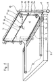
- the rear closing door 15 essentially consists of a panel 16 supported by a spacer 17 at the ends of which are mounted rollers 19.
- the panel 16 is equipped with brackets 14 fixed on the rails 8 which are arranged so as to be able to slide in slides arranged in the base of the frame 11 of the station 10
- the external dimensions of the panel 16 of the door 15 are very slightly smaller, of the order of 5 to 10 millimeters, than the internal dimensions of the rear frame 18 of the frame 11 described above.
- the seal between the pneumatic overpressure prevailing inside the internal volume V of the single-sided station 10 and the outside atmospheric air is produced here by upper horizontal brushes 72, lower 74 and by side brushes 76 reported by screwing or riveting along the outer periphery of the frame 16 of the door 15, the bristles of these upper 72, lower 74 and lateral brushes being oriented towards the outside.
- these brushes are made of nylon wire having sufficient rigidity even after long periods of use.
- the door locking device 15 comprises four hooks 30, distributed in pairs in the height of the panel 16, each of the hooks 30 being mounted substantially in the vicinity of each of the four corners of the panel 16 of the door 15.
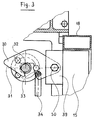
- each hook 30 is mounted on a support 39 while being oriented perpendicular to the door 15 and this is movable in rotation, in a vertical plane, around a pivot 50.
- the hooks 30 of a lateral pair, as shown in FIG. 2 are interconnected by a pull tab vertical 34 each end of which is connected to its respective hook 30 by a pivot.
- the two pairs of hooks 30, connected by the vertical pulls 34 are also coupled by a horizontal axis 40 mounted, on the internal face of the panel 16 of the door 15, in bearings 38, constituted in this case of simple perforated and welded plates against the panel 16.
- a horizontal axis 40 mounted, on the internal face of the panel 16 of the door 15, in bearings 38, constituted in this case of simple perforated and welded plates against the panel 16.
- Each end of this axis 40 is completed by an arm 36, substantially horizontal, the ends of these arms 36 being connected by a pivot to the corresponding vertical bar 34.
- This horizontal axis 40 is also completed with a central arm 42, preferably oriented downwards, the end of which is connected, also by a pivot, to a control lever 44 horizontally passing through the panel 16 of the door 15 through an orifice whose dimensions are just sufficient to allow translation of this lever without loss of pneumatic pressure.
- each hook 30 has an internal notch 33 provided to engage on a locking pin 32 located, in correspondence, in the side wall 4 of the frame 11 of the station 10. More in particular, the front part of this internal notch 33 has a strong forward curvature so that, once these hooks 30 engage on the axes 32 and the door 15 being pushed back by the overpressure prevailing in the station 10, these hooks 30 completely surround the locking pin 32 and can no longer be lifted directly, thus preventing any untimely movement towards the rear of the door 15.
- each hook 30 is obliquely oriented downward with the upper part higher than the locking pin 32.
- the closing of this door 15 is particularly easy because, once the gluing unit 20 is rolled inside the station 10, just push this door 15, the rails 8 sliding inside their slides located in the frame 11, until the hooks 30 meet the locking pins 32. Thanks to the oblique front portion of these hooks 30 ' , these will be lifted automatically until the internal notches 33 arrive at these axes, the hooks 30 immediately falling by their weight onto the locking axes 32.
- the relatively simple design of the locking and sealing system of this door 15 ensures better safety in the use of the machine, in the event of residual overpressure in station 10, by preventing the untimely opening of the latter, and by authorizing an easy and safe closing of the station 10 by a simple push on the door 10.
Landscapes
- Engineering & Computer Science (AREA)
- Mechanical Engineering (AREA)
- Specific Sealing Or Ventilating Devices For Doors And Windows (AREA)
- Machines For Manufacturing Corrugated Board In Mechanical Paper-Making Processes (AREA)
Applications Claiming Priority (2)
| Application Number | Priority Date | Filing Date | Title |
|---|---|---|---|
| CH193792 | 1992-06-19 | ||
| CH1937/92 | 1992-06-19 |
Publications (2)
| Publication Number | Publication Date |
|---|---|
| EP0574875A1 true EP0574875A1 (de) | 1993-12-22 |
| EP0574875B1 EP0574875B1 (de) | 1996-03-13 |
Family
ID=4222094
Family Applications (1)
| Application Number | Title | Priority Date | Filing Date |
|---|---|---|---|
| EP19930109522 Expired - Lifetime EP0574875B1 (de) | 1992-06-19 | 1993-06-15 | Tür für die einseitige Station einer Wellpappen-Herstellungsmaschine |
Country Status (4)
| Country | Link |
|---|---|
| US (1) | US5360505A (de) |
| EP (1) | EP0574875B1 (de) |
| JP (1) | JPH0818388B2 (de) |
| DE (1) | DE69301777T2 (de) |
Cited By (1)
| Publication number | Priority date | Publication date | Assignee | Title |
|---|---|---|---|---|
| CN106003844A (zh) * | 2016-05-26 | 2016-10-12 | 佛山市富利包装机械有限公司 | 一种瓦楞机一体式墙板及其换辊机构 |
Families Citing this family (3)
| Publication number | Priority date | Publication date | Assignee | Title |
|---|---|---|---|---|
| US9580946B2 (en) * | 2015-07-22 | 2017-02-28 | Provisur Technologies, Inc. | Screw conveyor having linked latch closure |
| CN109051394B (zh) * | 2018-08-15 | 2024-09-06 | 四川宏华石油设备有限公司 | 一种柔性水罐锁紧装置 |
| CN109051393B (zh) * | 2018-08-15 | 2024-09-06 | 四川宏华石油设备有限公司 | 一种柔性水罐锁紧装置 |
Citations (5)
| Publication number | Priority date | Publication date | Assignee | Title |
|---|---|---|---|---|
| US3844597A (en) * | 1973-08-29 | 1974-10-29 | D Elrod | Safety latch |
| GB1459411A (en) * | 1973-02-28 | 1976-12-22 | Hillier C N | Pressure vessels |
| EP0179395A1 (de) * | 1984-10-26 | 1986-04-30 | PETERS MASCHINENFABRIK GmbH | Auftragswerk für eine Wellpappenanlage |
| US4941695A (en) * | 1989-05-18 | 1990-07-17 | Pullman Leasing Company | Hatch cover assembly |
| GB2247032A (en) * | 1990-07-13 | 1992-02-19 | Simon Container Mach Ltd | Apparatus for manufacturing single-faced corrugated board |
Family Cites Families (4)
| Publication number | Priority date | Publication date | Assignee | Title |
|---|---|---|---|---|
| US2970718A (en) * | 1959-09-28 | 1961-02-07 | Everest & Jennings | Sterilizer door |
| US5160400A (en) * | 1990-05-24 | 1992-11-03 | United Container Machinery Group, Inc. | Corrugating apparatus having a liquid filled seal roll |
| US5110396A (en) * | 1990-06-14 | 1992-05-05 | The Langston Corporation | Floating air seal for an apparatus for manufacturing single faced corrugated board |
| US5145549A (en) * | 1991-08-19 | 1992-09-08 | Bhs-Bayerische Berg-, Hutten-Und Salzwerke Ag | Apparatus for producing one-sided corrugated paperboard |
-
1993
- 1993-06-15 EP EP19930109522 patent/EP0574875B1/de not_active Expired - Lifetime
- 1993-06-15 DE DE69301777T patent/DE69301777T2/de not_active Expired - Fee Related
- 1993-06-18 US US08/078,047 patent/US5360505A/en not_active Expired - Fee Related
- 1993-06-21 JP JP14925993A patent/JPH0818388B2/ja not_active Expired - Lifetime
Patent Citations (5)
| Publication number | Priority date | Publication date | Assignee | Title |
|---|---|---|---|---|
| GB1459411A (en) * | 1973-02-28 | 1976-12-22 | Hillier C N | Pressure vessels |
| US3844597A (en) * | 1973-08-29 | 1974-10-29 | D Elrod | Safety latch |
| EP0179395A1 (de) * | 1984-10-26 | 1986-04-30 | PETERS MASCHINENFABRIK GmbH | Auftragswerk für eine Wellpappenanlage |
| US4941695A (en) * | 1989-05-18 | 1990-07-17 | Pullman Leasing Company | Hatch cover assembly |
| GB2247032A (en) * | 1990-07-13 | 1992-02-19 | Simon Container Mach Ltd | Apparatus for manufacturing single-faced corrugated board |
Cited By (2)
| Publication number | Priority date | Publication date | Assignee | Title |
|---|---|---|---|---|
| CN106003844A (zh) * | 2016-05-26 | 2016-10-12 | 佛山市富利包装机械有限公司 | 一种瓦楞机一体式墙板及其换辊机构 |
| CN106003844B (zh) * | 2016-05-26 | 2018-06-26 | 佛山市富利包装机械有限公司 | 一种瓦楞机一体式墙板及其换辊机构 |
Also Published As
| Publication number | Publication date |
|---|---|
| JPH0818388B2 (ja) | 1996-02-28 |
| DE69301777D1 (de) | 1996-04-18 |
| US5360505A (en) | 1994-11-01 |
| DE69301777T2 (de) | 1996-08-08 |
| EP0574875B1 (de) | 1996-03-13 |
| JPH06340012A (ja) | 1994-12-13 |
Similar Documents
| Publication | Publication Date | Title |
|---|---|---|
| CA2286577C (fr) | Dispositif de guidage d'une porte a rideau souple | |
| EP1334255B2 (de) | Verschlussvorrichtung für das schliessen einer öffnung | |
| CH639045A5 (fr) | Dispositif pour introduire des paquets de feuilles dans une machine les travaillant. | |
| EP0421850A1 (de) | Verfahren und Vorrichtung zur Herstellung, zum Verschliessen und Verbinden der Klappen einer Kiste, insbesondere einer amerikanischen Kiste aus Pappe | |
| CH373688A (fr) | Procédé pour insérer une ébauche de séparation pliable entre des rangées de récipients à emballer et machine pour la mise en oeuvre de ce procédé | |
| EP0669274A1 (de) | Vorrichtung zum seitlichen Ausrichten von flachen Gegenständen auf einem Tisch | |
| EP0788990B1 (de) | Antriebsvorrichtung für Postgut | |
| FR2963322A1 (fr) | Dispositif d'operculage avec plaques support interchangeables pour supporter des contenants de formats differents | |
| EP0574875B1 (de) | Tür für die einseitige Station einer Wellpappen-Herstellungsmaschine | |
| FR2543513A1 (fr) | Machine a palettiser pour recipients | |
| FR2765191A1 (fr) | Procede et machine de collage automatique d'un film plastique thermoretractable sur le fond d'une caisse ouverte | |
| EP3526025B1 (de) | Vorrichtung und verfahren zur entfernung einer schachtel von einem dorn | |
| EP3526024B1 (de) | Verfahren und vorrichtung zum formen eines rohlings um eine spindel | |
| EP4460463B1 (de) | Übergabebehälter zum übergeben von artikeln in einen karton | |
| FR2464190A1 (fr) | Dispositif d'obturation de recipients au moyen d'un couvercle en un materiau en feuille plastiquement deformable | |
| EP4326639B1 (de) | Verpackung mit mitteln zum halten eines gegenstandes | |
| EP1074393B1 (de) | Papierstaubeseitigungsvorrichtung für einen Zuführer einer Frankiermaschine | |
| FR3148010A1 (fr) | Procédé et machine d’emballage pour la fermeture par une coiffe d'une caisse de forme parallélépipédique rectangle ouverte sur le dessus | |
| EP2143359A1 (de) | Kessel zur Wärmebehandlung | |
| FR2654066A1 (fr) | Appareil pour positionner des alveoles receptrices de fruits et legumes dans des caisses en carton selon le principe de fermeture des caisses dites "caisses americaines" et le procede de positionnement des alveoles dans les caisses. | |
| EP0175999A1 (de) | Vorrichtung zum Einschieben von Blättern in einen Briefumschlag | |
| FR2639611A1 (fr) | Dispositif de pose de coiffe sur une charge emballee par banderolage | |
| FR2705953A1 (fr) | Dispositif de transfert de liasses de feuilles d'une machine imprimante ou copieuse vers une machine de finition. | |
| EP0609164B1 (de) | Automatische Verschiebevorrichtung für Filterpresse | |
| FR2755665A1 (fr) | Machine encartonneuse verticale et procede de fermeture d'etui |
Legal Events
| Date | Code | Title | Description |
|---|---|---|---|
| PUAI | Public reference made under article 153(3) epc to a published international application that has entered the european phase |
Free format text: ORIGINAL CODE: 0009012 |
|
| 17P | Request for examination filed |
Effective date: 19930621 |
|
| AK | Designated contracting states |
Kind code of ref document: A1 Designated state(s): DE GB IT |
|
| 17Q | First examination report despatched |
Effective date: 19950731 |
|
| GRAA | (expected) grant |
Free format text: ORIGINAL CODE: 0009210 |
|
| AK | Designated contracting states |
Kind code of ref document: B1 Designated state(s): DE GB IT |
|
| ITF | It: translation for a ep patent filed | ||
| REF | Corresponds to: |
Ref document number: 69301777 Country of ref document: DE Date of ref document: 19960418 |
|
| GBT | Gb: translation of ep patent filed (gb section 77(6)(a)/1977) |
Effective date: 19960530 |
|
| PLBE | No opposition filed within time limit |
Free format text: ORIGINAL CODE: 0009261 |
|
| STAA | Information on the status of an ep patent application or granted ep patent |
Free format text: STATUS: NO OPPOSITION FILED WITHIN TIME LIMIT |
|
| 26N | No opposition filed | ||
| REG | Reference to a national code |
Ref country code: GB Ref legal event code: IF02 |
|
| PGFP | Annual fee paid to national office [announced via postgrant information from national office to epo] |
Ref country code: DE Payment date: 20020430 Year of fee payment: 10 |
|
| PGFP | Annual fee paid to national office [announced via postgrant information from national office to epo] |
Ref country code: GB Payment date: 20020605 Year of fee payment: 10 |
|
| PG25 | Lapsed in a contracting state [announced via postgrant information from national office to epo] |
Ref country code: GB Free format text: LAPSE BECAUSE OF NON-PAYMENT OF DUE FEES Effective date: 20030615 |
|
| PG25 | Lapsed in a contracting state [announced via postgrant information from national office to epo] |
Ref country code: DE Free format text: LAPSE BECAUSE OF NON-PAYMENT OF DUE FEES Effective date: 20040101 |
|
| GBPC | Gb: european patent ceased through non-payment of renewal fee |
Effective date: 20030615 |
|
| PG25 | Lapsed in a contracting state [announced via postgrant information from national office to epo] |
Ref country code: IT Free format text: LAPSE BECAUSE OF NON-PAYMENT OF DUE FEES Effective date: 20050615 |