EP0574926A2 - Procédé et dispositif de fabrication de céramique en nitrure de silicium - Google Patents
Procédé et dispositif de fabrication de céramique en nitrure de silicium Download PDFInfo
- Publication number
- EP0574926A2 EP0574926A2 EP93109718A EP93109718A EP0574926A2 EP 0574926 A2 EP0574926 A2 EP 0574926A2 EP 93109718 A EP93109718 A EP 93109718A EP 93109718 A EP93109718 A EP 93109718A EP 0574926 A2 EP0574926 A2 EP 0574926A2
- Authority
- EP
- European Patent Office
- Prior art keywords
- sintering
- silicon nitride
- furnace
- gas
- atmosphere
- Prior art date
- Legal status (The legal status is an assumption and is not a legal conclusion. Google has not performed a legal analysis and makes no representation as to the accuracy of the status listed.)
- Granted
Links
- 229910052581 Si3N4 Inorganic materials 0.000 title claims abstract description 69
- HQVNEWCFYHHQES-UHFFFAOYSA-N silicon nitride Chemical compound N12[Si]34N5[Si]62N3[Si]51N64 HQVNEWCFYHHQES-UHFFFAOYSA-N 0.000 title claims abstract description 69
- 238000000034 method Methods 0.000 title claims abstract description 39
- 230000008569 process Effects 0.000 title claims abstract description 37
- 239000000919 ceramic Substances 0.000 title 1
- 238000005245 sintering Methods 0.000 claims abstract description 186
- 239000000463 material Substances 0.000 claims abstract description 62
- 239000000843 powder Substances 0.000 claims abstract description 27
- 239000000203 mixture Substances 0.000 claims abstract description 14
- 238000005192 partition Methods 0.000 claims abstract description 10
- 238000010438 heat treatment Methods 0.000 claims abstract description 6
- UGFAIRIUMAVXCW-UHFFFAOYSA-N Carbon monoxide Chemical compound [O+]#[C-] UGFAIRIUMAVXCW-UHFFFAOYSA-N 0.000 claims description 5
- 230000015572 biosynthetic process Effects 0.000 claims description 4
- 238000007493 shaping process Methods 0.000 claims description 4
- 230000007850 degeneration Effects 0.000 abstract description 14
- 239000003795 chemical substances by application Substances 0.000 abstract description 5
- 239000007789 gas Substances 0.000 description 64
- VYPSYNLAJGMNEJ-UHFFFAOYSA-N Silicium dioxide Chemical compound O=[Si]=O VYPSYNLAJGMNEJ-UHFFFAOYSA-N 0.000 description 28
- OKTJSMMVPCPJKN-UHFFFAOYSA-N Carbon Chemical compound [C] OKTJSMMVPCPJKN-UHFFFAOYSA-N 0.000 description 23
- 229910052799 carbon Inorganic materials 0.000 description 21
- 239000010410 layer Substances 0.000 description 18
- 229910052681 coesite Inorganic materials 0.000 description 14
- 229910052906 cristobalite Inorganic materials 0.000 description 14
- 239000000377 silicon dioxide Substances 0.000 description 14
- 235000012239 silicon dioxide Nutrition 0.000 description 14
- 229910052682 stishovite Inorganic materials 0.000 description 14
- 229910052905 tridymite Inorganic materials 0.000 description 14
- 238000013001 point bending Methods 0.000 description 8
- 229910052582 BN Inorganic materials 0.000 description 5
- PZNSFCLAULLKQX-UHFFFAOYSA-N Boron nitride Chemical compound N#B PZNSFCLAULLKQX-UHFFFAOYSA-N 0.000 description 5
- PNEYBMLMFCGWSK-UHFFFAOYSA-N aluminium oxide Inorganic materials [O-2].[O-2].[O-2].[Al+3].[Al+3] PNEYBMLMFCGWSK-UHFFFAOYSA-N 0.000 description 5
- 230000000052 comparative effect Effects 0.000 description 5
- 238000000227 grinding Methods 0.000 description 5
- HBMJWWWQQXIZIP-UHFFFAOYSA-N silicon carbide Chemical compound [Si+]#[C-] HBMJWWWQQXIZIP-UHFFFAOYSA-N 0.000 description 5
- 229910010271 silicon carbide Inorganic materials 0.000 description 5
- LFQSCWFLJHTTHZ-UHFFFAOYSA-N Ethanol Chemical compound CCO LFQSCWFLJHTTHZ-UHFFFAOYSA-N 0.000 description 4
- 238000006243 chemical reaction Methods 0.000 description 4
- 238000009770 conventional sintering Methods 0.000 description 4
- 229910052593 corundum Inorganic materials 0.000 description 4
- 230000008020 evaporation Effects 0.000 description 4
- 238000001704 evaporation Methods 0.000 description 4
- 229910002804 graphite Inorganic materials 0.000 description 4
- 239000010439 graphite Substances 0.000 description 4
- 238000004519 manufacturing process Methods 0.000 description 4
- 239000002344 surface layer Substances 0.000 description 4
- 229910001845 yogo sapphire Inorganic materials 0.000 description 4
- 230000000694 effects Effects 0.000 description 3
- 230000003993 interaction Effects 0.000 description 3
- 239000004677 Nylon Substances 0.000 description 2
- QVGXLLKOCUKJST-UHFFFAOYSA-N atomic oxygen Chemical compound [O] QVGXLLKOCUKJST-UHFFFAOYSA-N 0.000 description 2
- 230000008859 change Effects 0.000 description 2
- 239000007791 liquid phase Substances 0.000 description 2
- 208000020442 loss of weight Diseases 0.000 description 2
- 238000005259 measurement Methods 0.000 description 2
- 238000006396 nitration reaction Methods 0.000 description 2
- 229920001778 nylon Polymers 0.000 description 2
- 229910052760 oxygen Inorganic materials 0.000 description 2
- 239000001301 oxygen Substances 0.000 description 2
- 239000012071 phase Substances 0.000 description 2
- 230000009467 reduction Effects 0.000 description 2
- 238000005979 thermal decomposition reaction Methods 0.000 description 2
- 229920000049 Carbon (fiber) Polymers 0.000 description 1
- 238000010521 absorption reaction Methods 0.000 description 1
- 230000033228 biological regulation Effects 0.000 description 1
- 239000004917 carbon fiber Substances 0.000 description 1
- 238000007796 conventional method Methods 0.000 description 1
- 239000013078 crystal Substances 0.000 description 1
- 238000002425 crystallisation Methods 0.000 description 1
- 230000008025 crystallization Effects 0.000 description 1
- 238000005520 cutting process Methods 0.000 description 1
- 238000000354 decomposition reaction Methods 0.000 description 1
- 230000003247 decreasing effect Effects 0.000 description 1
- 229910003460 diamond Inorganic materials 0.000 description 1
- 239000010432 diamond Substances 0.000 description 1
- 238000009826 distribution Methods 0.000 description 1
- 230000006872 improvement Effects 0.000 description 1
- 238000012986 modification Methods 0.000 description 1
- 230000004048 modification Effects 0.000 description 1
- 229910003465 moissanite Inorganic materials 0.000 description 1
- 238000007789 sealing Methods 0.000 description 1
- WFKWXMTUELFFGS-UHFFFAOYSA-N tungsten Chemical compound [W] WFKWXMTUELFFGS-UHFFFAOYSA-N 0.000 description 1
- 229910052721 tungsten Inorganic materials 0.000 description 1
- 239000010937 tungsten Substances 0.000 description 1
- 238000009423 ventilation Methods 0.000 description 1
- 208000016261 weight loss Diseases 0.000 description 1
- 230000004580 weight loss Effects 0.000 description 1
Images

Classifications
-
- F—MECHANICAL ENGINEERING; LIGHTING; HEATING; WEAPONS; BLASTING
- F27—FURNACES; KILNS; OVENS; RETORTS
- F27B—FURNACES, KILNS, OVENS OR RETORTS IN GENERAL; OPEN SINTERING OR LIKE APPARATUS
- F27B5/00—Muffle furnaces; Retort furnaces; Other furnaces in which the charge is held completely isolated
- F27B5/04—Muffle furnaces; Retort furnaces; Other furnaces in which the charge is held completely isolated adapted for treating the charge in vacuum or special atmosphere
-
- C—CHEMISTRY; METALLURGY
- C04—CEMENTS; CONCRETE; ARTIFICIAL STONE; CERAMICS; REFRACTORIES
- C04B—LIME, MAGNESIA; SLAG; CEMENTS; COMPOSITIONS THEREOF, e.g. MORTARS, CONCRETE OR LIKE BUILDING MATERIALS; ARTIFICIAL STONE; CERAMICS; REFRACTORIES; TREATMENT OF NATURAL STONE
- C04B35/00—Shaped ceramic products characterised by their composition; Ceramics compositions; Processing powders of inorganic compounds preparatory to the manufacturing of ceramic products
- C04B35/515—Shaped ceramic products characterised by their composition; Ceramics compositions; Processing powders of inorganic compounds preparatory to the manufacturing of ceramic products based on non-oxide ceramics
- C04B35/58—Shaped ceramic products characterised by their composition; Ceramics compositions; Processing powders of inorganic compounds preparatory to the manufacturing of ceramic products based on non-oxide ceramics based on borides, nitrides, i.e. nitrides, oxynitrides, carbonitrides or oxycarbonitrides or silicides
- C04B35/584—Shaped ceramic products characterised by their composition; Ceramics compositions; Processing powders of inorganic compounds preparatory to the manufacturing of ceramic products based on non-oxide ceramics based on borides, nitrides, i.e. nitrides, oxynitrides, carbonitrides or oxycarbonitrides or silicides based on silicon nitride
- C04B35/593—Shaped ceramic products characterised by their composition; Ceramics compositions; Processing powders of inorganic compounds preparatory to the manufacturing of ceramic products based on non-oxide ceramics based on borides, nitrides, i.e. nitrides, oxynitrides, carbonitrides or oxycarbonitrides or silicides based on silicon nitride obtained by pressure sintering
- C04B35/5935—Shaped ceramic products characterised by their composition; Ceramics compositions; Processing powders of inorganic compounds preparatory to the manufacturing of ceramic products based on non-oxide ceramics based on borides, nitrides, i.e. nitrides, oxynitrides, carbonitrides or oxycarbonitrides or silicides based on silicon nitride obtained by pressure sintering obtained by gas pressure sintering
-
- C—CHEMISTRY; METALLURGY
- C04—CEMENTS; CONCRETE; ARTIFICIAL STONE; CERAMICS; REFRACTORIES
- C04B—LIME, MAGNESIA; SLAG; CEMENTS; COMPOSITIONS THEREOF, e.g. MORTARS, CONCRETE OR LIKE BUILDING MATERIALS; ARTIFICIAL STONE; CERAMICS; REFRACTORIES; TREATMENT OF NATURAL STONE
- C04B35/00—Shaped ceramic products characterised by their composition; Ceramics compositions; Processing powders of inorganic compounds preparatory to the manufacturing of ceramic products
- C04B35/622—Forming processes; Processing powders of inorganic compounds preparatory to the manufacturing of ceramic products
- C04B35/64—Burning or sintering processes
-
- F—MECHANICAL ENGINEERING; LIGHTING; HEATING; WEAPONS; BLASTING
- F27—FURNACES; KILNS; OVENS; RETORTS
- F27B—FURNACES, KILNS, OVENS OR RETORTS IN GENERAL; OPEN SINTERING OR LIKE APPARATUS
- F27B21/00—Open or uncovered sintering apparatus; Other heat-treatment apparatus of like construction
Definitions
- the present invention relates to a process of producing a silicon nitride (Si3N4) sintered body, and an apparatus for producing the same.
- a sintering aid such as Y203, Al203, MgO, or the like, is mixed with silicon nitride powder and the mixture is formed into a shaped body.
- the shaped body is then sintered at a high temperature, about 1800 °C, in an atmosphere of a N2 gas or an inactive gas including the N2 gas to produce a shaped silicon nitride sintered body.
- FIG. 1 A conventional furnace for sintering a shaped body is shown in Fig. 1 (PRIOR ART).
- the conventional furnace has an adiabatic material 4, a heating source such as a heater 5, and a jig 2 for supporting the shaped body.
- Conventional furnace materials typically comprise carbon-containing materials.
- JP '1270 discloses a process in which a CO2 gas or a CO2 gas and a CO gas are mixed with an N2 gas atmosphere, and an O2 is generated by decomposition of the CO2 gas to increase the oxygen partial pressure to thereby reduce evaporation or nitration of SiO2 contained in the surface of the silicon nitride powder.
- the surface of the shaped silicon nitride body is degenerated during sintering in the furnace by contact with the sintering gas atmosphere.
- the mechanical properties of the sintered body are degraded. Therefore, the degenerated layer must be removed by grinding or the like.
- the degree of degeneration or the thickness of the degenerated layer varies depending on the sintering batches.
- the sintered body is diffucult to be ground, and when the degenerated layer becomes thicker, its thickness varies more largely among the respective sintered bodies, so that portions to be processed must be made larger. Accordingly, the cost of producing a sintered shaped body is significantly increased and the productivity is significantly decreased.
- An object of the present invention is to provide a satisfactory process to be capable of solving the above problems, for producing a shaped silicon nitride sintered body having a high density and a superior strength wherein the degeneration of its surface during sintering is reduced.
- Another object of the present invention is to provide an economical furnace for sintering a shaped silicon nitride body which solves the problems associated with conventional processes.
- a first embodiment is a process for producing a shaped silicon nitride sintered body comprising the steps of shaping a mixture of silicon nitride powder and a sintering aid to prepare a shaped body, and sintering the shaped body in an atmosphere of an N2 gas or an inactive gas including an N2 gas, characterized in that a CO (carbon monooxide gas) concentration in the atmosphere contacting the shaped body during sintering is not higher than about 30 ppm.
- a CO carbon monooxide gas
- a second embodiment comprises a process for producing a silicon nitride sinter comprising the steps of shaping a mixture of silicon nitride powder and a sintering aid to prepare a shaped body, sintering the shaped body in a sintering case at least the inner surface of which comprises carbon-free heat-proof materials, when required, supporting the shaped body by a jig comprising carbon-free heat-proof materials, replacing the atmosphere in the sintering case with an N2 gas or an inactive gas including an N2 gas, and sintering the shaped body in the sintering case under conditions such that the atmosphere in a furnace cannot come in contact with the shaped body.
- a third embodiment is an apparatus for sintering the shaped body comprising a furnace core chamber defined by providing partitions inside the furnace and a heating source, and an atmospheric gas supplying pipe for supplying an N2 gas or an inactive gas including an N2 gas into the furnace core chamber, wherein at least the inner surface of the furnace core chamber comprises carbon-free heat-proof materials.
- the shaped body is disposed in the furnace core chamber directly and, when required, the shaped body is supported by a jig comprising carbon-free heat-proof materials.
- Fig. 1 is a sectional view illustrating a conventional furnace for producing a conventional silicon nitride sintered body.
- Fig. 2 is a sectional view illustrating an example of a furnace for producing a silicon nitride sintered body according to the present invention.
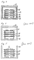
- Fig. 3 is a sectional view illustrating a sintering case used in a process according to the present invention.
- Fig. 4 is a sectional view illustrating a conventional sintering case used for comparison in the examples.
- Fig. 5 is a sectional view illustrating a conventional sintering case used for comparison in the examples.
- the inventors analyzed conventional sintering processes and furnaces including, for example, the components of the sintering gas atmosphere during sintering, the materials comprising the furnace, the loss in weight of a sinter, and therefrom, the inventors surprisingly discovered that CO in the sintering gas atmosphere has a strong relationship to the formation of the degenerated layer on the surface of a shaped silicon nitride sintered body.
- SiO2 contained in the surface of the Si3N4 powder reacts with CO in the sintering atmosphere by the reaction shown in the following Formula 1, and is gasified as SiO, which is reduced by carbon-containing materials in the furnace by the reaction of Formula 2 to thereby produce CO again:
- Formula 2 SiO + 2C ⁇ SiC + CO ⁇ CO2 produced in the above Formula 1 is also reduced by carbon-containing materials to thereby produce CO again as shown in the following Formula 3.
- the concentration of CO produced in the furnace is affected by, for example, the quantity of moisture or residual air in the furnace, the flow rate of the atmospheric gas, and the quantity of a formed body, so that the thickness or degree of the degenerated layer on the surface varies in accordance with each sintered lot.
- the concentration of CO in the atmosphere contacting the shaped body during sintering is reduced in order to cut off the chain reactions shown in the above Formulae 1 to 4. If the concentration of CO in an N2 gas or an inactive gas including an N2 gas used as a sintering atmosphere is not higher than about 30 ppm, the evaporation of SiO2 or the sintering aid from the shaped body is prevented which significantly reduces the production of a degenerated layer in the surface of an obtained sinter.
- the concentration of CO in the sintering gas atmosphere is greater than about 30 ppm, the degeneration of the sintered surface advances rapidly and the thickness of the degenerated layer is significantly increased.
- concentration of CO the more the sintering aid or SiO2 evaporates from the shaped silicon nitride body during sintering.
- the sintering aid evaporates from the inside as well as from the surface of the shaped body during sintering so that a composition of the liquid phase consisting of the sintering aids formed thereof is changed which significantly deteriorates the properties of sintered body and makes it impossible to obtain a sintered body with adequate strength.
- a high sintering temperature in a range of from about 1,700 to about 1,900 °C is conventional in order to compensate for the lower sinterability described above.
- the sintering temperature can be within a range of from about 1,300 to about 1,800 °C and preferably within a range of from 1,400 to 1,750 °C.
- the adequate sintering temperature should be set to obtain the relative density within above temperature range is not lower than about 96%.
- the sintering temperature is lower than about 1,300 °C, no liquid phase is formed by the sintering aid and sintering will not occur.
- sintering is performed at a temperature not higher than about the temperature where thermal decomposition of silicon nitride starts, which is typically about 1,800 °C. Therefore, the pressure of the N2 gas or the sintering atmosphere including the N2 gas can be set at about atmospheric pressure, such as for example, within a region of from about 1.0 to about 1.1 atmospheric pressure. Therefore, according to this invention, sintering can be performed under atmospheric pressure of N2 gas. Thus an equipment or operation for pressurizing the atmosphere is not necessary.
- the shaped silicon nitride sintered body obtained in the first embodiment is secondarily sintered at a temperature within a range of from about 1,300 to about 1,800 °C in an N2 gas atmosphere not lower than about 10 atmospheric pressure, it is possible to make the sintered body dense and to increase the strength thereof. If the temperature is lower than about 1,300 °C or the N2 gas atmosphere is lower than about 10 atmospheric pressure, the effect of making the sintered body dense cannot be obtained. If the temperature is greater than about 1,800 °C, uneven growth of crystal grains occurs while the sintered body is made dense, so that the minute structure is changed, which is not preferable. It is not necessary to control the concentration of CO in the atmosphere during secondary sintering.
- the production of a degenerated layer in the surface of an obtained sintered body is reduced by cutting off the contact between the sintering atmosphere including CO and the shaped body during sintering.
- a sintering case surrounding the shaped body, and when necessary a jig for supporting the shaped body in the sintering case can be used which comprise carbon-free heat-proof materials. Because there is no contact between a sintering atmosphere gas containing CO and the shaped body during sintering, SiO2 and the sintering aid are not altered or evaporated from the shaped body. A shaped silicon nitride sintered body having extremely little degenerated layer on its surface is thereby obtained.
- the sintering case used in the second embodiment is formed of materials being heat-proof at sintering temperatures and at least the inner surface of the sintering case comprises carbon-free heat-proof materials.
- carbon-free heat-proof material Any conventional carbon-free heat-proof material can be used.
- Preferred examples of carbon-free heat-proof materials include silicon carbide, silicon nitride and boron nitride.
- the sintering case comprises a vessel 12 having an opening portion through which a formed body is inserted and a cap 13 for stopping up the opening portion so that atmospheric ventilation can be forced through the gap between the vessel and the cap, but atmospheres inside and outside of the sintering case are not mixed with each other if there is not a large difference of pressure between the inside and the outside the sintering case.
- the sintering case further includes an inside panel 14 of carbon free material such as boron nitride, which is 3 mm thick and is disposed on the inside of the vessel.
- One or plurality of shaped bodies 11 are set in the sintering case directly or by using the support of a jig 15 and 16 formed of carbon-free heat-proof materials.
- the atmosphere in the sintering case is replaced by an N2 gas or an inactive gas including an N2 gas.
- the replacement of the atmosphere inside the sintering case can be performed, for example, through the gap between the cap and the sintering case after the cap is closed, or the cap may be closed after replacing the atmosphere in the sintering case.
- the shaped body in the sintering case can be put in a conventional furnace, and sintered.
- the second embodiment has many advantages in view of the cost and productivity because equipment or procedures for providing pressure to the furnace are not necessary and it is possible to use an open type continuously sintering furnace such as a tray-pusher type, belt-conveyor type, roller-hearth type, or the like, which is superior in evenness of heating, in sintering rate, and in sintering efficiency. Further, according to the second embodiment, even if the concentration of CO is larger than 30 ppm contrary to the first embodiment, since the shaped body is protected by the case, the same effect as that of the first embodiment can be obtained. Further, in this embodiment, the carbon-free heat-proof material is only disposed inside the sintering case, which is easily performed. Also, many variations in practice are conceived so that the embodiment is practical.
- the cap of the sintering case is preferably sealed so that gas cannot flow into the sintering case from the furnace.
- the atmosphere in the furnace does not flow into the sintering case if the pressure in the sintering case is almost the same as or higher than the pressure in the furnace, so that the shaped body does not contact the atmosphere in the furnace.
- the furnace atmospheric gas supplied into the furnace is the same as the atmospheric gas charged into the sintering case, and the pressure in the sintering case is made higher than the pressure of the furnace atmosphere during sintering.
- a shaped silicon nitride sintered body made according to the second embodiment can be subjected to a second sintering step as defined above in the first embodiment.
- a conventional furnace is shown in Fig. 1.
- the furnace materials such as an adiabatic material 4, a heater 5, and a jig 2 used for supporting a shaped body 1 are typically carbon-containing materials.
- the conventional furnace also includes an outer wall 3, a gas supplying pipe 6, an atmosphere exhaust pipe 7, and an atmosphere measuring hole 8.
- a furnace according to the third embodiment is shown in Fig. 2.
- the furnace materials such as an adiabatic material 24 and a heater 25 comprise carbon-free heat-proof materials, or if they comprise carbon-containing materials, CO produced by the interaction of residual moisture or air and the carbon-containing materials is prevented from contacting the shaped body 1) during sintering, so that the concentration of CO in the atmosphere contacting the shaped body is not higher than about 30 ppm.
- a partition 29 is disposed between a shaped body 1 to be sintered and furnace materials such as an adiabatic material 24 provided inside an outer wall 23 of a furnace, and between the shaped body 1 and a heating source such as a heater 25, and the whole of the partition 29 or only the side of the partition 29 facing to a furnace core chamber 30 comprises carbon-free heat-proof materials.
- any conventional carbon-free heat-proof material can be used.
- Preferred examples of the carbon-free heat-proof materials include silicon carbide, silicon nitride, boron nitride.
- the jig 22 also comprises carbon-free heat-proof materials.
- an N2 gas or an inactive gas including an N2 gas is led into the furnace core chamber 30 through an atmospheric gas supplying pipe 26.
- the atmospheric gas passes through gaps of the partitions 29, and is exhausted through an atmospheric gas exhaust pipe 27.
- the pressure in the furnace core chamber 30 is set to be higher than the pressure in the furnace, so that a CO gas produced outside the furnace core chamber 30 by the interaction of carbon-containing materials and air or the like is prevented from intruding into the furnace core chamber 30.
- the atmospheric gas can be sampled from a measuring hole 28 so that the concentration of CO in the atmosphere contacting the shaped body 1 in the furnace core chamber 30 can be analyzed and measured continuously.
- all the furnace materials, such as the adiabatic material 24, the heater 25, and the jig 22 used for supporting a shaped body 1 comprise carbon-free heat-proof materials, so that the production of CO from carbon-containing heat-proof materials is prevented and the concentration of CO in the atmosphere contacting the shaped body is not higher than about 30 ppm.
- a high-alumina adiabatic material and a heater of SiC, tungsten or the like can be used, and in such a case, preferably, the sintering temperature is not higher than about 1,500 °C so that the durability and life of the heater in the sintering atmosphere is not reduced.
- Examples 1-3 represent embodiments 1 and 3.
- Examples 4-6 represent embodiment 2.
- the thus prepared shaped bodies were sintered for 4 hours at 1,450 °C in 1.0 atmospheric pressure and then 2 hours at 1,580 °C using a jig comprising the materials shown in the following Table 1, while an N2 gas of initial CO concentration shown in the following Table 1 was led in through an atmospheric gas supplying pipe.
- a graphite heater and a carbon-containing adiabatic material were used in each furnace, and SiC was used as the carbon-free heat-proof material in the partition 29 in the furnace of Fig. 2.
- the atmospheric gas in the furnace core chamber during sintering was continuously sampled using the atmospheric gas measuring hole 28 to measure the concentration of CO continuously, and the results are shown Table 1.
- the relative densities were obtained by dividing apparent densities obtained through Archimedes' principle by their theoretical densities.
- the loss in weight during sintering was obtained by dividing the difference in weight between the sinters and the weight of the shaped bodies by the weight of the shaped bodies and then multiplying by 100%.
- the three-point bending strengths were measured according to JIS R1601.
- JIS R1601 The three-point bending strengths were measured according to JIS R1601.
- this measuring method there were prepared samples in which only a surface to which a tensile stress was applied at the measurement, was not ground or ground to a prescribed depth.
- Table 2 shows the relative densities, the loss in weights and the three-point bending strengths which were measured without grinding the sintered surfaces to which the tensile stress was applied and when the sintered surfaces to which the tensile stress was applied were ground to depths of 0.1 mm, 0.3 mm, 0.5 mm and 1.0 mm using a diamond abrasive (#800).
- Table 2 illustrates that the strengths of samples (a) to (e), in which the concentration of CO in the atmosphere during sintering was controlled to be not higher than about 30 ppm, were almost equal in strength between the surface and their insides when portions of 0.1 mm were ground off. Therefore, the degeneration of their surfaces was extremely light.
- Table 2 illustrates that comparative samples (f) to (i), in which the concentration of CO was greater than about 30 ppm, had thick degenerated layers and the reduction of strength caused by degeneration reached well inside the sinters, particularly in the samples (q) and (i). Samples (q) and (i) also exhibited a large loss of weight during sintering.
- the sinters of the samples (a) to (e) obtained in Example 1 were secondarily sintered for 2 hours at 1,650 °C in an N2 gas atmosphere at a pressure of 100 atmospheric pressures, and respective sinters of samples (a') to (e') were obtained.
- the respective sinters were measured in the same manner as in Example 1, and their obtained relative densities and three-point bending strengths are shown in Table 3.
- Formed bodies made up in the same manner as in Example 1 were sintered five times under the same conditions as those of the samples (a) and (i) in the above Table 1, so that two sets of five samples (a-1) to (a-5) and (i-1) to (i-5) respectively were obtained.
- the characteristics of samples (a-1) to (a-5) and (i-1) to (i-5) were measured in the same manner as in Example 1 together with the concentration of CO in the sintering atmosphere during sintering. The results are shown in Table 4.
- the concentration of CO in the sintering atmosphere contacting the shaped body during sintering is reduced so as to be not higher than about 30 ppm, to obtain a silicon nitride sinter having high density and superior strength.
- a sinter made according to the first and third embodiments has an extremely small degenerated layer on the surface, the amount of degenerated layer to be ground off is significantly reduced. Furthermore, the sintering can be performed at a lower temperature and lower pressure than in conventional processes, which results in a large reduction in the cost and a large improvement in the strength of the sinter.
- sintering cases Ten samples of the thus formed bodies were set in each of three kinds of sintering cases shown in Figs. 3 to 5.
- Each of the sintering cases in Figs. 3 and 4 comprise a box vessel 12 and a cap 13 which were made of carbon, and the sintering case in Fig. 5 comprised only a vessel 12 made of carbon.
- the sintering case in Fig. 3 had an inside panel 14 of boron nitride which was 3 mm thick.
- a plate-like jig 15 and a columnar jig 16 made of boron nitride was used in the sintering case in Fig. 3, and a plate-like jig 17 and a columnar jig 18 made of carbon were used in the sintering cases in Figs. 4 and 5.
- the respective sintering cases including the shaped bodies were put into a conventional batch furnace in which a graphite heater and a carbon-containing adiabatic material were used, and an N2 gas gas led into the furnace after the furnace and the sintering cases were exhausted in vacuum, so that the atmospheres in the furnace and the sintering cases were replaced by the N2 gas.
- Table 5 illustrates that the sample (aa) made according to the second embodiment had the same strength as the inside of the sinter after grinding off about 0.1 mm, which means that any degeneration of the surface was very little.
- the sample (aa) was higher in density and superior in strength compared to the samples (bb) and (cc) which were made according to conventional methods.
- sintering cases shown in fig. 3 and five sintering cases shown in Fig. 5 were prepared. Ten samples of shaped bodies made in the same manner as in Example 4 were set in the respective sintering cases, and a pair of the sintering case shown in fig. 3 and the sintering case shown in Fig. 5 were put at the same time into the same furnace as that in Example 4. After replacing the atmosphere in the same manner as in Example 4, sintering under the same conditions as in Example 4 was carried out. Such sintering was repeated five time, so that two sets of five samples (aa-1) to (aa-5) using the sintering case of Fig. 3 and (cc-1) to (cc-5) using the sintering case of Fig. 5, were obtained.
- Example 4 Ten samples of shaped bodies made up in the same manner as in Example 4 were set in each of the three kinds of sintering cases shown in Figs. 3 to 5 in the same manner as in Example 4.
- the respective sintering cases including the shaped bodies were sintered using a tray pusher type furnace in which a vacuum gas replacement room was provided at an entrance portion.
- the tray pusher type furnace was a conventional continuous furnace using a graphite heater and using carbon-containing materials as the furnace materials and the materials for the carrier tray.
- the sintering cases containing shaped bodies therein were put on the tray, and the atmosphere in each of the sintering cases was replaced by an N2 gas after being exhausted in vacuum in the vacuum gas replacement room.
- the internal pressure of each of the sintering cases of Figs. 3 and 4 was made to be 1.05 atmospheric pressure.
- the respective sintering cases were carried into the furnace and the furnace atmosphere was N2 gas at 1.0 atmospheric pressure and 200 mm H2O.
- the sintering cases passed through an increasing temperature zone and the sintering cases were subjected to sintering while the sintering cases were conveyed at a constant speed so that the sintering cases were passed through, in six hours, the uniform heat zones of 1,450 °C and 1,580°C (zone length ratio 1,450°C : 1,580°C 2 : 1).
- the concentration of CO in the furnace atmosphere before the sintering cases were put into the furnace was 120 ppm.
- Table 7 shows the results of measuring, as in Example 1, of the relative density, the loss in weight after sintering, and three-point bending strengths at room temperature of each of the obtained sinters.
- the shaped sintered bodies in the comparative examples (samples ee and ff) exhibited low strength, large amounts of degeneration of the surface layer, significant loss in weight during sintering and a low density.
- Table 8 illustrate that the process according to the second embodiment can produce shaped sintered bodies having significantly increased strength, significantly reduced degeneration of the surface layer during sintering with littly variance of the properties.
- the characteristics of the respective sinters were measured in the same manner as in Example 1 to thereby obtain relative densities and three-point bending strengths after grinding off 0.1 mm from the surface.
- the results are shown in Table 9.
- the results in Table 9 illustrate that the strength of a sinter can be significantly improved by secondary sintering.
- the furnace atmosphere in which CO is produced in sintering is prevented from contacting the shaped body during sintering, and the atmosphere surrounding the shaped body is also prevented from contacting carbon-containing materials which can produce CO. Therefore, the process according to the second embodiment can produce shaped sintered bodies having significantly increased strength, significantly reduced degeneration of the surface layer during sintering and significantly reduced loss of weight during sintering with a very high precision.
- the second embodiment results in a remarkable decrease in cost and increase in productivity compared to conventional processes because the shaped sintered body has an extremely small degenerated layer on its surface which results in a significantly reduced load required for grinding off the degenerated layer, and sintering can be performed at a lower temperature and lower pressure.
- the second embodiment also results in significantly increased cost savings because a conventional continuous furnace can be used.
Landscapes
- Engineering & Computer Science (AREA)
- Chemical & Material Sciences (AREA)
- Ceramic Engineering (AREA)
- Manufacturing & Machinery (AREA)
- Mechanical Engineering (AREA)
- General Engineering & Computer Science (AREA)
- Materials Engineering (AREA)
- Structural Engineering (AREA)
- Organic Chemistry (AREA)
- Inorganic Chemistry (AREA)
- Ceramic Products (AREA)
Applications Claiming Priority (4)
| Application Number | Priority Date | Filing Date | Title |
|---|---|---|---|
| JP04184416A JP3111656B2 (ja) | 1992-06-18 | 1992-06-18 | 窒化ケイ素焼結体の製造方法及び製造装置 |
| JP184417/92 | 1992-06-18 | ||
| JP184416/92 | 1992-06-18 | ||
| JP04184417A JP3111657B2 (ja) | 1992-06-18 | 1992-06-18 | 窒化ケイ素焼結体の製造方法 |
Publications (3)
| Publication Number | Publication Date |
|---|---|
| EP0574926A2 true EP0574926A2 (fr) | 1993-12-22 |
| EP0574926A3 EP0574926A3 (fr) | 1995-02-15 |
| EP0574926B1 EP0574926B1 (fr) | 1997-11-19 |
Family
ID=26502490
Family Applications (1)
| Application Number | Title | Priority Date | Filing Date |
|---|---|---|---|
| EP93109718A Expired - Lifetime EP0574926B1 (fr) | 1992-06-18 | 1993-06-17 | Procédé et dispositif de fabrication de céramique en nitrure de silicium |
Country Status (3)
| Country | Link |
|---|---|
| US (1) | US5533930A (fr) |
| EP (1) | EP0574926B1 (fr) |
| DE (1) | DE69315261T2 (fr) |
Cited By (2)
| Publication number | Priority date | Publication date | Assignee | Title |
|---|---|---|---|---|
| US6743394B2 (en) * | 1999-03-03 | 2004-06-01 | Sumitomo Special Metals Co., Ltd. | Case for use in sintering process to produce rare-earth magnet, and method for producing rare-earth magnet |
| EP1832565A4 (fr) * | 2005-08-03 | 2007-10-17 | Ibiden Co Ltd | Gabarit pour la cuisson de carbure de silicium et procédé de production d un corps poreux de carbure de silicium |
Families Citing this family (10)
| Publication number | Priority date | Publication date | Assignee | Title |
|---|---|---|---|---|
| US6696015B2 (en) * | 1999-03-03 | 2004-02-24 | Sumitomo Special Metals Co., Ltd. | Method for producing rare-earth magnet |
| JP5202810B2 (ja) * | 2006-02-06 | 2013-06-05 | 古河電気工業株式会社 | グラファイト加熱炉および光ファイバの製造方法 |
| US7531769B2 (en) * | 2006-06-13 | 2009-05-12 | Guy Smith | Carbon fiber composite muffle |
| CN101556110B (zh) * | 2009-05-19 | 2012-07-11 | 江苏奥能耐火材料有限公司 | 含碳材料无氧化烧成电炉 |
| CN102466403A (zh) * | 2010-11-05 | 2012-05-23 | 施丽萍 | 推车炉窑 |
| CN106288767B (zh) * | 2016-09-18 | 2018-06-15 | 山东大学 | 一种碳碳复合材料高温连续加热炉 |
| US20220065533A1 (en) * | 2020-08-28 | 2022-03-03 | Desktop Metal, Inc. | Systems, devices, and methods for purifying atmosphere in a vacuum furnace |
| JP2024512431A (ja) * | 2021-03-16 | 2024-03-19 | ディーエスビー テクノロジーズ, エルエルシー | 連続焼結炉で使用するためのラッキングシステム |
| DE102021108239B3 (de) | 2021-03-31 | 2022-09-01 | Vacuumschmelze Gmbh & Co. Kg | Verfahren zur Wärmebehandlung eines Gegenstands |
| DE102021108241B3 (de) | 2021-03-31 | 2022-07-14 | Vacuumschmelze Gmbh & Co. Kg | Verfahren zur Wärmebehandlung eines Gegenstands mit zumindest einer Seltenen Erde mit einem hohen Dampfdruck |
Family Cites Families (14)
| Publication number | Priority date | Publication date | Assignee | Title |
|---|---|---|---|---|
| US2789808A (en) * | 1954-11-05 | 1957-04-23 | Lee Wilson | Method of and apparatus for controlling circulation of furnace atmosphere |
| JPS5849509B2 (ja) * | 1975-10-11 | 1983-11-04 | 科学技術庁無機材質研究所長 | 窒化珪素焼結体の製造法 |
| DE3266050D1 (en) * | 1981-10-12 | 1985-10-10 | Sumitomo Electric Industries | Method for sintering silicon nitride |
| FR2517665B1 (fr) * | 1981-12-08 | 1986-01-31 | Ceraver | Procede de fabrication d'un materiau fritte a base de nitrure de silicium, et materiau obtenu par ce procede |
| US4773852A (en) * | 1985-06-11 | 1988-09-27 | Denki Kagaku Kogyo Kabushiki Kaisha | Pyrolytic boron nitride crucible and method for producing the same |
| DE3685806T2 (de) * | 1985-11-18 | 1992-12-17 | Ngk Insulators Ltd | Herstellung von gesinterten siliziumnitridformkoerpern. |
| IT1210310B (it) * | 1987-06-19 | 1989-09-14 | Alberto Albonetti | Parete radiante,in particolare per scambiatori,forni a muffola esimili |
| DE3825955A1 (de) * | 1987-07-30 | 1989-02-16 | Ngk Insulators Ltd | Verfahren zur herstellung homogener siliciumnitrid-sinterkoerper |
| JP2524201B2 (ja) * | 1988-08-22 | 1996-08-14 | 日本特殊陶業株式会社 | 窒化珪素質焼結体及びその製造方法 |
| US5188781A (en) * | 1988-09-10 | 1993-02-23 | Hoechst Aktiengesellschaft | Silicon nitride ceramic and a process for its preparation |
| EP0399107B1 (fr) * | 1989-05-22 | 1996-03-20 | Sumitomo Electric Industries, Ltd. | Corps fritté en nitrure de silicium ayant une résistance élevée et procédé de fabrication |
| US5225127A (en) * | 1989-07-18 | 1993-07-06 | Sumitomo Electric Industries, Ltd. | Process for production of sintered silicon nitride made article |
| US5173458A (en) * | 1990-12-28 | 1992-12-22 | Sumitomo Electric Industries, Ltd. | Silicon nitride sintered body and process for producing the same |
| JP3007432B2 (ja) * | 1991-02-19 | 2000-02-07 | 東京エレクトロン株式会社 | 熱処理装置 |
-
1993
- 1993-06-17 DE DE69315261T patent/DE69315261T2/de not_active Expired - Fee Related
- 1993-06-17 EP EP93109718A patent/EP0574926B1/fr not_active Expired - Lifetime
-
1994
- 1994-03-29 US US08/219,719 patent/US5533930A/en not_active Expired - Fee Related
Cited By (2)
| Publication number | Priority date | Publication date | Assignee | Title |
|---|---|---|---|---|
| US6743394B2 (en) * | 1999-03-03 | 2004-06-01 | Sumitomo Special Metals Co., Ltd. | Case for use in sintering process to produce rare-earth magnet, and method for producing rare-earth magnet |
| EP1832565A4 (fr) * | 2005-08-03 | 2007-10-17 | Ibiden Co Ltd | Gabarit pour la cuisson de carbure de silicium et procédé de production d un corps poreux de carbure de silicium |
Also Published As
| Publication number | Publication date |
|---|---|
| DE69315261T2 (de) | 1998-03-12 |
| EP0574926A3 (fr) | 1995-02-15 |
| EP0574926B1 (fr) | 1997-11-19 |
| DE69315261D1 (de) | 1998-01-02 |
| US5533930A (en) | 1996-07-09 |
Similar Documents
| Publication | Publication Date | Title |
|---|---|---|
| EP0574926A2 (fr) | Procédé et dispositif de fabrication de céramique en nitrure de silicium | |
| Schneider et al. | A theoretical and experimental approach to the active-to-passive transition in the oxidation of silicon carbide: Experiments at high temperatures and low total pressures | |
| US8883069B2 (en) | Dense boron carbide ceramic and process for producing the same | |
| EP0276334A1 (fr) | Matériau en nitrure et carbure de silicium et son procédé de fabrication | |
| JPH027908B2 (fr) | ||
| KR950014714B1 (ko) | 휘스커 강화 세라믹과 그것의 클래드/열간 정압압축 성형방법 | |
| EP0726237A2 (fr) | Corps fritté à base de nitrure de silicium et procédé de sa fabrication | |
| US5376601A (en) | Sintered product of aluminum nitride, a process for the preparation thereof, and a baking jig using the same | |
| US5504046A (en) | Process for producing reaction-bonded silicon carbide refractory product | |
| KR970042431A (ko) | 반응소결 세라믹스 및 이의 제조방법 | |
| EP0225087B1 (fr) | Fabrication d'un corps fritté en nitrure de silicium | |
| EKSTRÖM et al. | α‐β sialon ceramics made from different silicon nitride powders | |
| US5006491A (en) | Process for production of nitride ceramic shapes | |
| AU627777B2 (en) | Increasing aluminum nitride thermal conductivity via pre- densification treatment | |
| US4801414A (en) | Production of silicon nitride sintered body | |
| 田畑周平 et al. | Liquid phase sintering and mechanical properties of SiC with rare-earth oxide | |
| JP3111657B2 (ja) | 窒化ケイ素焼結体の製造方法 | |
| JP3111656B2 (ja) | 窒化ケイ素焼結体の製造方法及び製造装置 | |
| EP0120004B1 (fr) | Procede de preparation d'ingredients en poudre pour les consolider ulterieurement | |
| Dutta et al. | Characterization and properties of controlled nucleation thermochemical deposition (CNTD)-silicon carbide | |
| US5876660A (en) | Sintered reaction-bonded silicon nitride components | |
| Thomas et al. | Microwave Nitrudation of Silicon Compacts Utilizing a Temperature Gradient | |
| EP0120849B1 (fr) | Procede de fabrication de nitrure de silicium comprime a chaud de haute resistance mecanique | |
| WO2025084413A1 (fr) | Comprimé fritté à base de nitrure de silicium et son procédé de production | |
| KR100242829B1 (ko) | 알루미나 강화 방법 |
Legal Events
| Date | Code | Title | Description |
|---|---|---|---|
| PUAI | Public reference made under article 153(3) epc to a published international application that has entered the european phase |
Free format text: ORIGINAL CODE: 0009012 |
|
| AK | Designated contracting states |
Kind code of ref document: A2 Designated state(s): DE FR GB IT NL SE |
|
| PUAL | Search report despatched |
Free format text: ORIGINAL CODE: 0009013 |
|
| AK | Designated contracting states |
Kind code of ref document: A3 Designated state(s): DE FR GB IT NL SE |
|
| 17P | Request for examination filed |
Effective date: 19950214 |
|
| 17Q | First examination report despatched |
Effective date: 19951121 |
|
| GRAG | Despatch of communication of intention to grant |
Free format text: ORIGINAL CODE: EPIDOS AGRA |
|
| GRAH | Despatch of communication of intention to grant a patent |
Free format text: ORIGINAL CODE: EPIDOS IGRA |
|
| GRAH | Despatch of communication of intention to grant a patent |
Free format text: ORIGINAL CODE: EPIDOS IGRA |
|
| GRAA | (expected) grant |
Free format text: ORIGINAL CODE: 0009210 |
|
| AK | Designated contracting states |
Kind code of ref document: B1 Designated state(s): DE FR GB IT NL SE |
|
| PG25 | Lapsed in a contracting state [announced via postgrant information from national office to epo] |
Ref country code: NL Free format text: LAPSE BECAUSE OF FAILURE TO SUBMIT A TRANSLATION OF THE DESCRIPTION OR TO PAY THE FEE WITHIN THE PRESCRIBED TIME-LIMIT Effective date: 19971119 |
|
| ITF | It: translation for a ep patent filed | ||
| REF | Corresponds to: |
Ref document number: 69315261 Country of ref document: DE Date of ref document: 19980102 |
|
| PG25 | Lapsed in a contracting state [announced via postgrant information from national office to epo] |
Ref country code: SE Free format text: LAPSE BECAUSE OF FAILURE TO SUBMIT A TRANSLATION OF THE DESCRIPTION OR TO PAY THE FEE WITHIN THE PRESCRIBED TIME-LIMIT Effective date: 19980219 |
|
| ET | Fr: translation filed | ||
| NLV1 | Nl: lapsed or annulled due to failure to fulfill the requirements of art. 29p and 29m of the patents act | ||
| PLBE | No opposition filed within time limit |
Free format text: ORIGINAL CODE: 0009261 |
|
| STAA | Information on the status of an ep patent application or granted ep patent |
Free format text: STATUS: NO OPPOSITION FILED WITHIN TIME LIMIT |
|
| 26N | No opposition filed | ||
| REG | Reference to a national code |
Ref country code: GB Ref legal event code: IF02 |
|
| PGFP | Annual fee paid to national office [announced via postgrant information from national office to epo] |
Ref country code: FR Payment date: 20030610 Year of fee payment: 11 |
|
| PGFP | Annual fee paid to national office [announced via postgrant information from national office to epo] |
Ref country code: GB Payment date: 20030611 Year of fee payment: 11 |
|
| PGFP | Annual fee paid to national office [announced via postgrant information from national office to epo] |
Ref country code: DE Payment date: 20030626 Year of fee payment: 11 |
|
| PG25 | Lapsed in a contracting state [announced via postgrant information from national office to epo] |
Ref country code: GB Free format text: LAPSE BECAUSE OF NON-PAYMENT OF DUE FEES Effective date: 20040617 |
|
| PG25 | Lapsed in a contracting state [announced via postgrant information from national office to epo] |
Ref country code: DE Free format text: LAPSE BECAUSE OF NON-PAYMENT OF DUE FEES Effective date: 20050101 |
|
| GBPC | Gb: european patent ceased through non-payment of renewal fee |
Effective date: 20040617 |
|
| PG25 | Lapsed in a contracting state [announced via postgrant information from national office to epo] |
Ref country code: FR Free format text: LAPSE BECAUSE OF NON-PAYMENT OF DUE FEES Effective date: 20050228 |
|
| REG | Reference to a national code |
Ref country code: FR Ref legal event code: ST |
|
| PG25 | Lapsed in a contracting state [announced via postgrant information from national office to epo] |
Ref country code: IT Free format text: LAPSE BECAUSE OF NON-PAYMENT OF DUE FEES;WARNING: LAPSES OF ITALIAN PATENTS WITH EFFECTIVE DATE BEFORE 2007 MAY HAVE OCCURRED AT ANY TIME BEFORE 2007. THE CORRECT EFFECTIVE DATE MAY BE DIFFERENT FROM THE ONE RECORDED. Effective date: 20050617 |