EP0574945A1 - Dispositif d'actionnement pour un élément de soupape - Google Patents
Dispositif d'actionnement pour un élément de soupape Download PDFInfo
- Publication number
- EP0574945A1 EP0574945A1 EP93109798A EP93109798A EP0574945A1 EP 0574945 A1 EP0574945 A1 EP 0574945A1 EP 93109798 A EP93109798 A EP 93109798A EP 93109798 A EP93109798 A EP 93109798A EP 0574945 A1 EP0574945 A1 EP 0574945A1
- Authority
- EP
- European Patent Office
- Prior art keywords
- base body
- actuating lever
- actuating
- lever
- translators
- Prior art date
- Legal status (The legal status is an assumption and is not a legal conclusion. Google has not performed a legal analysis and makes no representation as to the accuracy of the status listed.)
- Granted
Links
Images
Classifications
-
- F—MECHANICAL ENGINEERING; LIGHTING; HEATING; WEAPONS; BLASTING
- F16—ENGINEERING ELEMENTS AND UNITS; GENERAL MEASURES FOR PRODUCING AND MAINTAINING EFFECTIVE FUNCTIONING OF MACHINES OR INSTALLATIONS; THERMAL INSULATION IN GENERAL
- F16K—VALVES; TAPS; COCKS; ACTUATING-FLOATS; DEVICES FOR VENTING OR AERATING
- F16K31/00—Actuating devices; Operating means; Releasing devices
- F16K31/004—Actuating devices; Operating means; Releasing devices actuated by piezoelectric means
- F16K31/007—Piezoelectric stacks
-
- H—ELECTRICITY
- H02—GENERATION; CONVERSION OR DISTRIBUTION OF ELECTRIC POWER
- H02N—ELECTRIC MACHINES NOT OTHERWISE PROVIDED FOR
- H02N2/00—Electric machines in general using piezoelectric effect, electrostriction or magnetostriction
- H02N2/02—Electric machines in general using piezoelectric effect, electrostriction or magnetostriction producing linear motion, e.g. actuators; Linear positioners ; Linear motors
- H02N2/04—Constructional details
- H02N2/043—Mechanical transmission means, e.g. for stroke amplification
Definitions
- the invention relates to a device for actuating a valve element according to the preamble of claim 1.
- Electromagnets are usually used to actuate hydraulic directional control valves. With a supply voltage of e.g. 12 volts are required to generate the required tightening force of typically 100 N coil currents of a few hundred milliamps.
- electromagnetically operated valves have the disadvantage that a permanent coil current is required to maintain the active switching state.
- the invention is based on the object of specifying a device of the type mentioned at the outset, for the actuation of which only a very low electrical power is required.
- Piezoelectric translators are known per se. They each consist of a stack of piezoelectric elements made of a ferroelectric ceramic material.
- the typical change in thickness of a piezoceramic disc is only 1 10 ⁇ 3 mm with an applied field strength of 1000 V / mm (if the expansion does not counteract any clamping force), but the stack can be expanded according to the required actuation path, i.e. the translator by stacking a corresponding number of piezo disks on top of each other.
- Piezo-electric translators are characterized by freedom from wear, fast switching times and high actuating force at the beginning of the switching path. The latter feature in particular makes them particularly suitable for actuating hydraulic valves, since the force required on the tappet of a hydraulic valve is greatest at the beginning of the actuating path, while the hydraulic counterforces subsequently decrease rapidly. This requirement corresponds to the displacement / force characteristic of piezo-electric translators, whereas, with a drive with an electromagnet with constant coil current, the lifting force increases with the travel.
- a type of translator manufactured by Hoechst-CeramTec has a height of 16 mm and an expansion path of 20 ⁇ m at a voltage of 400 volts. When clamped, it exerts an expansion force of 1500 N. From these data it follows that a lever ratio of 1:10 is required for the required travel of 200 ⁇ m.
- the thermal expansion coefficient of piezoceramic is about a factor 2 smaller than that of steel (13 ° 10 ⁇ 6). With a temperature change of 30 °, this means a difference in the thematic length change of more than 3 ⁇ m per 16 mm. This is already a considerable one Part of the total stroke of 20 ⁇ m that can be achieved with the translator.
- the solution according to the invention now eliminates this problem in that the opposite action of two translators is used to pivot or tilt the actuating lever. This completely compensates for non-electrical expansion effects that are based, for example, on a temperature change and thus occur in the same way in both stacks. This means that the full stroke of the translators can be used.
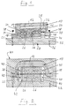
- Fig. 1 denotes a rocker arm or operating lever which has a substantially C-shaped shape. It comprises a central or longitudinal leg 12 and two transverse legs 14 and 16 perpendicular to this.
- actuating sections 18 and 20 directed outwards, on each of which an actuating plunger 22 is arranged.
- the actuating lever 10 is mounted on a base body 24 so that it can be given away or tilted.
- the actuating lever 10 is mounted and tilted with the aid of two piezoelectric translators 26, that is to say stacks, which are constructed from individual piezoelectric elements which are parallel to one another with their stacking axes, but antiparallel with their direction of action between the cross leg 14 and a clamping surface 28 of the base body 24, which is essentially parallel to this, are clamped.
- the tensioning force is applied by two tension screws or tensioning bolts 30 running between the translators 26, which act on the one hand on the transverse legs 14 and on the other hand on an extension 32 of the base body 24 having the tensioning surface 28.
- the translators 26 are clamped between the cross leg 14 and the clamping surface 28 such that they can each be pivoted slightly relative to the clamping surfaces about axes 34 which are perpendicular to the plane of the drawing and which extend through the tips of the triangles at the corners of the translators 26.
- the plungers 22 are guided in bores 36 of the base body 24.
- the joints containing the joint axes 34 are realized by thin material bridges 40, via which clamping jaws 42, 44 are connected to the cross leg 14 or the base body 24.
- the practical embodiment shown is extremely compact and practically wear-free since it has no joint parts susceptible to wear.
Landscapes
- Engineering & Computer Science (AREA)
- General Engineering & Computer Science (AREA)
- Mechanical Engineering (AREA)
- Mechanically-Actuated Valves (AREA)
- Electrically Driven Valve-Operating Means (AREA)
Applications Claiming Priority (2)
| Application Number | Priority Date | Filing Date | Title |
|---|---|---|---|
| DE4220177 | 1992-06-19 | ||
| DE4220177A DE4220177A1 (de) | 1992-06-19 | 1992-06-19 | Vorrichtung zur Betätigung eines Ventilelementes |
Publications (2)
| Publication Number | Publication Date |
|---|---|
| EP0574945A1 true EP0574945A1 (fr) | 1993-12-22 |
| EP0574945B1 EP0574945B1 (fr) | 1997-09-03 |
Family
ID=6461430
Family Applications (1)
| Application Number | Title | Priority Date | Filing Date |
|---|---|---|---|
| EP93109798A Expired - Lifetime EP0574945B1 (fr) | 1992-06-19 | 1993-06-18 | Dispositif d'actionnement pour un élément de soupape |
Country Status (3)
| Country | Link |
|---|---|
| US (1) | US5328149A (fr) |
| EP (1) | EP0574945B1 (fr) |
| DE (2) | DE4220177A1 (fr) |
Cited By (5)
| Publication number | Priority date | Publication date | Assignee | Title |
|---|---|---|---|---|
| DE4445642A1 (de) * | 1994-12-21 | 1996-06-27 | Marco Systemanalyse Entw | Piezoaktuatorisches Antriebs- bzw. Verstellelement |
| DE19646511C1 (de) * | 1996-11-12 | 1998-05-14 | Marco Systemanalyse Entw | Piezoaktuatorisches Antriebs- oder Verstellelement |
| WO2001024288A3 (fr) * | 1999-09-30 | 2001-12-27 | Bosch Gmbh Robert | Dispositif de reglage permettant de commander un dispositif de regulation et/ou d'arret |
| EP0994516A3 (fr) * | 1998-10-13 | 2004-08-04 | Nordson Corporation | Amplificateur mécanique |
| DE19817802B4 (de) * | 1996-11-12 | 2009-08-06 | Marco Systemanalyse Und Entwicklung Gmbh | Piezoaktuatorisches Antriebs- oder Verstellelement |
Families Citing this family (32)
| Publication number | Priority date | Publication date | Assignee | Title |
|---|---|---|---|---|
| DE4411569C1 (de) * | 1994-04-02 | 1995-07-20 | Itw Dynatec Gmbh Klebetechnik | Auftragskopf zur dosierten Abgabe von strömenden Medien |
| DE19521060A1 (de) * | 1995-06-09 | 1996-12-12 | Wolf Gmbh Richard | Haltearmsystem, insbesondere für chirurgische Instrumente, mit Armsegmenten und Klemmvorrichtungen zum Arretieren der Armsegmente |
| DE19521478C1 (de) * | 1995-06-13 | 1996-09-12 | Itw Dynatec Gmbh Klebetechnik | Auftragskopf zur dosierten Abgabe von strömenden Medien |
| DE19538596A1 (de) * | 1995-10-17 | 1997-04-24 | Fluidtech Gmbh | Piezoaktorbetätigtes Steuerventil |
| DE29710006U1 (de) * | 1997-06-09 | 1998-11-05 | Bürkert Werke GmbH & Co., 74653 Ingelfingen | Miniaturisierte Ventileinrichtung |
| DE19859436B4 (de) * | 1998-12-22 | 2009-12-24 | Heidelberger Druckmaschinen Ag | Digitale Farbdosierung |
| DE19859437A1 (de) | 1998-12-22 | 2000-06-29 | Heidelberger Druckmasch Ag | Farbwerk |
| DE19928182A1 (de) * | 1999-06-19 | 2000-07-27 | Bosch Gmbh Robert | Piezoaktor zur Betätigung eines mechanischen Bauteils |
| DE19931990C1 (de) * | 1999-07-09 | 2001-01-11 | Festo Ag & Co | Elektroventil |
| EP1091423A3 (fr) * | 1999-10-08 | 2004-05-19 | Siemens Aktiengesellschaft | Dispositif d'entraínement d'un élément de positionnement |
| GB9927574D0 (en) * | 1999-11-22 | 2000-01-19 | Pbt Ip Limited | Valve incorporating active material |
| US6836056B2 (en) | 2000-02-04 | 2004-12-28 | Viking Technologies, L.C. | Linear motor having piezo actuators |
| WO2001067431A1 (fr) | 2000-03-07 | 2001-09-13 | Viking Technologies, Inc. | Procede et systeme d'accord automatique d'un instrument a cordes |
| US6717332B2 (en) | 2000-04-18 | 2004-04-06 | Viking Technologies, L.C. | Apparatus having a support structure and actuator |
| US6548938B2 (en) | 2000-04-18 | 2003-04-15 | Viking Technologies, L.C. | Apparatus having a pair of opposing surfaces driven by a piezoelectric actuator |
| AU2001272733A1 (en) * | 2000-07-19 | 2002-02-05 | Orbotech Ltd. | Apparatus and method for electrical testing of electrical circuits |
| US6759790B1 (en) | 2001-01-29 | 2004-07-06 | Viking Technologies, L.C. | Apparatus for moving folded-back arms having a pair of opposing surfaces in response to an electrical activation |
| US6879087B2 (en) | 2002-02-06 | 2005-04-12 | Viking Technologies, L.C. | Apparatus for moving a pair of opposing surfaces in response to an electrical activation |
| US6924586B2 (en) * | 2002-06-21 | 2005-08-02 | Viking Technologies, L.C. | Uni-body piezoelectric motor |
| CN1781196A (zh) | 2003-04-04 | 2006-05-31 | 瓦伊金技术有限公司 | 一种智能材料致动器功的最佳化装置和方法 |
| US9341281B2 (en) | 2007-02-12 | 2016-05-17 | Colt Irrigation Llc | Fluid activated flow control apparatus |
| US7967509B2 (en) | 2007-06-15 | 2011-06-28 | S.C. Johnson & Son, Inc. | Pouch with a valve |
| DE102008006296A1 (de) * | 2008-01-28 | 2009-07-30 | Deutsches Zentrum für Luft- und Raumfahrt e.V. | Schubaktuator und mit einem solchen Schubaktuator versehener Träger |
| DE102010015171A1 (de) * | 2010-04-16 | 2011-10-20 | Fraunhofer-Gesellschaft zur Förderung der angewandten Forschung e.V. | Piezoelektrisches Aktormodul sowie piezoelektrischer Aktor mit einem solchen piezoelektrischen Aktormodul und Herstellungsverfahren für diese |
| WO2011144591A1 (fr) | 2010-05-17 | 2011-11-24 | Mindray Medical Sweden Ab | Amplificateur mécanique, système constitué de tels amplificateurs et procédé d'amplification mécanique d'un mouvement |
| US8624467B2 (en) | 2010-05-18 | 2014-01-07 | Mindray Medical Sweden Ab | Methods, systems, and devices for mechanical motion amplification |
| US10088849B2 (en) | 2014-01-23 | 2018-10-02 | Colt Irrigation, LLC | Fluid activated flow control apparatus |
| US10571937B1 (en) | 2014-01-23 | 2020-02-25 | Colt Irrigation, LLC | Valve control apparatus |
| US9599286B2 (en) | 2014-01-23 | 2017-03-21 | Colt Irrigation, LLC | Fluid activated flow control apparatus |
| DE102014101512A1 (de) | 2014-02-06 | 2015-08-06 | Marco Systemanalyse Und Entwicklung Gmbh | Piezoelektrische Stellvorrichtung |
| DE102016108811A1 (de) * | 2016-05-12 | 2017-11-16 | Marco Systemanalyse Und Entwicklung Gmbh | Piezoelektrische Stellvorrichtung |
| JP6818881B2 (ja) * | 2016-10-20 | 2021-01-20 | エーエスエムエル ネザーランズ ビー.ブイ. | 圧力制御弁、リソグラフィ装置のための流体ハンドリング構造、及びリソグラフィ装置 |
Citations (3)
| Publication number | Priority date | Publication date | Assignee | Title |
|---|---|---|---|---|
| EP0143128A1 (fr) * | 1983-11-29 | 1985-06-05 | Paul Julian Moloney | Commande de la distribution à soupape pour moteur à combustion interne et machines avec la même distribution à soupape |
| EP0165407A2 (fr) * | 1984-04-26 | 1985-12-27 | Nippon Enlarging Color Inc. | Soupape de régulation de débit avec organe d'asservissement piézo-électrique |
| DE3723287A1 (de) * | 1987-07-15 | 1989-01-26 | Kuhnke Gmbh Kg H | Elektrisch betaetigbares ventil |
Family Cites Families (5)
| Publication number | Priority date | Publication date | Assignee | Title |
|---|---|---|---|---|
| JPS6174901A (ja) * | 1984-09-19 | 1986-04-17 | Yamatake Honeywell Co Ltd | ノズル・フラツパ機構の変位調整機構 |
| US4787071A (en) * | 1987-03-12 | 1988-11-22 | Kreuter Manufacturing Co., Inc. | Piezoelectric/fluid pressure transducer apparatus |
| DE3739048C2 (de) * | 1987-11-17 | 2001-08-09 | Buerkert Gmbh | Mehrwegeventil |
| JPH02138501A (ja) * | 1988-11-17 | 1990-05-28 | Smc Corp | ノズルフラッパ機構 |
| EP0445340B1 (fr) * | 1990-03-09 | 1994-12-14 | Siemens Aktiengesellschaft | Soupape à commande piézoélectrique |
-
1992
- 1992-06-19 DE DE4220177A patent/DE4220177A1/de not_active Withdrawn
-
1993
- 1993-06-18 US US08/079,446 patent/US5328149A/en not_active Expired - Fee Related
- 1993-06-18 EP EP93109798A patent/EP0574945B1/fr not_active Expired - Lifetime
- 1993-06-18 DE DE59307238T patent/DE59307238D1/de not_active Expired - Fee Related
Patent Citations (3)
| Publication number | Priority date | Publication date | Assignee | Title |
|---|---|---|---|---|
| EP0143128A1 (fr) * | 1983-11-29 | 1985-06-05 | Paul Julian Moloney | Commande de la distribution à soupape pour moteur à combustion interne et machines avec la même distribution à soupape |
| EP0165407A2 (fr) * | 1984-04-26 | 1985-12-27 | Nippon Enlarging Color Inc. | Soupape de régulation de débit avec organe d'asservissement piézo-électrique |
| DE3723287A1 (de) * | 1987-07-15 | 1989-01-26 | Kuhnke Gmbh Kg H | Elektrisch betaetigbares ventil |
Non-Patent Citations (1)
| Title |
|---|
| PATENT ABSTRACTS OF JAPAN vol. 12, no. 73 (M-674)(2920) 8. März 1988 & JP-A-62 215 176 ( NOK CORP. ) 21. September 1987 * |
Cited By (6)
| Publication number | Priority date | Publication date | Assignee | Title |
|---|---|---|---|---|
| DE4445642A1 (de) * | 1994-12-21 | 1996-06-27 | Marco Systemanalyse Entw | Piezoaktuatorisches Antriebs- bzw. Verstellelement |
| US5900691A (en) * | 1994-12-21 | 1999-05-04 | Marco Systemanalyse Und Entwicklung Gmbh | Piezoelectrically actuated driving and adjusting element |
| DE19646511C1 (de) * | 1996-11-12 | 1998-05-14 | Marco Systemanalyse Entw | Piezoaktuatorisches Antriebs- oder Verstellelement |
| DE19817802B4 (de) * | 1996-11-12 | 2009-08-06 | Marco Systemanalyse Und Entwicklung Gmbh | Piezoaktuatorisches Antriebs- oder Verstellelement |
| EP0994516A3 (fr) * | 1998-10-13 | 2004-08-04 | Nordson Corporation | Amplificateur mécanique |
| WO2001024288A3 (fr) * | 1999-09-30 | 2001-12-27 | Bosch Gmbh Robert | Dispositif de reglage permettant de commander un dispositif de regulation et/ou d'arret |
Also Published As
| Publication number | Publication date |
|---|---|
| EP0574945B1 (fr) | 1997-09-03 |
| DE59307238D1 (de) | 1997-10-09 |
| DE4220177A1 (de) | 1993-12-23 |
| US5328149A (en) | 1994-07-12 |
Similar Documents
| Publication | Publication Date | Title |
|---|---|---|
| EP0574945B1 (fr) | Dispositif d'actionnement pour un élément de soupape | |
| EP0799502B1 (fr) | Element d'entrainement ou de reglage a actionnement piezo-electrique | |
| DE19940124C2 (de) | Plattform mit einem Verschiebungsverstärkungsmechanismus | |
| EP1192377A1 (fr) | Vanne piezo-electrique | |
| EP0356713A1 (fr) | Dispositif de positionnement actionné électromagnétiquement | |
| DE19653555C2 (de) | Piezoelektrischer Aktor | |
| AT403462B (de) | Einrichtung zum umstellen von weichen | |
| EP0207270A2 (fr) | Dispositif de commutation fonctionnant sans contact par détecteur de proximité | |
| EP0935054A2 (fr) | Vérin électromagnétique | |
| DE2903086A1 (de) | Elektromagnetische stelleinrichtung, insbesondere zum einstellen des stellarmes eines elektrohydraulischen servoventils | |
| DE102020103476B4 (de) | Ventilantrieb und Ventil | |
| CH664039A5 (de) | Einrichtung zur anpassung der wirkung eines elektromagneten an eine vom elektromagneten zu betaetigende komponente. | |
| EP3807552B1 (fr) | Système de freinage | |
| DE19946839A1 (de) | Verstelleinrichtung zum Ansteuern einer Regel- und/oder Absperrvorrichtung | |
| DE4425078A1 (de) | Biegeaktuator | |
| DE3906786C2 (fr) | ||
| DE19981030B4 (de) | Vorschubeinheit zum Bewegen von Bauteilen | |
| DE10156261C1 (de) | Greif- oder Spannvorrichtung | |
| DE20005996U1 (de) | Greifvorrichtung | |
| DE3327060A1 (de) | Greifer mit zwei gegeneinander beweglichen backen | |
| DE19822907B4 (de) | Elektromagnetischer Aktuator mit gelenkig abgestützter Rückstellfeder | |
| DE3018972C2 (de) | Magnetventil | |
| DE19858758C1 (de) | Vorrichtung und Verfahren zur Hubübertragung | |
| DE2406643C2 (de) | Einrichtung zur Justierung eines Kraftvergleichssystems | |
| DE29912258U1 (de) | Greifer zum Ergreifgen kleiner Gegenstände |
Legal Events
| Date | Code | Title | Description |
|---|---|---|---|
| PUAI | Public reference made under article 153(3) epc to a published international application that has entered the european phase |
Free format text: ORIGINAL CODE: 0009012 |
|
| AK | Designated contracting states |
Kind code of ref document: A1 Designated state(s): AT BE CH DE DK ES FR GB GR IE IT LI LU MC NL PT SE |
|
| RBV | Designated contracting states (corrected) |
Designated state(s): DE FR GB |
|
| 17P | Request for examination filed |
Effective date: 19940622 |
|
| 17Q | First examination report despatched |
Effective date: 19951129 |
|
| GRAG | Despatch of communication of intention to grant |
Free format text: ORIGINAL CODE: EPIDOS AGRA |
|
| GRAH | Despatch of communication of intention to grant a patent |
Free format text: ORIGINAL CODE: EPIDOS IGRA |
|
| GRAH | Despatch of communication of intention to grant a patent |
Free format text: ORIGINAL CODE: EPIDOS IGRA |
|
| GRAA | (expected) grant |
Free format text: ORIGINAL CODE: 0009210 |
|
| AK | Designated contracting states |
Kind code of ref document: B1 Designated state(s): DE FR GB |
|
| REF | Corresponds to: |
Ref document number: 59307238 Country of ref document: DE Date of ref document: 19971009 |
|
| GBT | Gb: translation of ep patent filed (gb section 77(6)(a)/1977) |
Effective date: 19971113 |
|
| ET | Fr: translation filed | ||
| PLBE | No opposition filed within time limit |
Free format text: ORIGINAL CODE: 0009261 |
|
| STAA | Information on the status of an ep patent application or granted ep patent |
Free format text: STATUS: NO OPPOSITION FILED WITHIN TIME LIMIT |
|
| 26N | No opposition filed | ||
| PGFP | Annual fee paid to national office [announced via postgrant information from national office to epo] |
Ref country code: GB Payment date: 19990525 Year of fee payment: 7 |
|
| PGFP | Annual fee paid to national office [announced via postgrant information from national office to epo] |
Ref country code: FR Payment date: 19990616 Year of fee payment: 7 |
|
| PGFP | Annual fee paid to national office [announced via postgrant information from national office to epo] |
Ref country code: DE Payment date: 19990811 Year of fee payment: 7 |
|
| PG25 | Lapsed in a contracting state [announced via postgrant information from national office to epo] |
Ref country code: GB Free format text: LAPSE BECAUSE OF NON-PAYMENT OF DUE FEES Effective date: 20000618 |
|
| GBPC | Gb: european patent ceased through non-payment of renewal fee |
Effective date: 20000618 |
|
| PG25 | Lapsed in a contracting state [announced via postgrant information from national office to epo] |
Ref country code: FR Free format text: LAPSE BECAUSE OF NON-PAYMENT OF DUE FEES Effective date: 20010228 |
|
| REG | Reference to a national code |
Ref country code: FR Ref legal event code: ST |
|
| PG25 | Lapsed in a contracting state [announced via postgrant information from national office to epo] |
Ref country code: DE Free format text: LAPSE BECAUSE OF NON-PAYMENT OF DUE FEES Effective date: 20010403 |