EP0575115A1 - Chemisches Schneidwerkzeug für Bohrlöcher - Google Patents
Chemisches Schneidwerkzeug für Bohrlöcher Download PDFInfo
- Publication number
- EP0575115A1 EP0575115A1 EP93304564A EP93304564A EP0575115A1 EP 0575115 A1 EP0575115 A1 EP 0575115A1 EP 93304564 A EP93304564 A EP 93304564A EP 93304564 A EP93304564 A EP 93304564A EP 0575115 A1 EP0575115 A1 EP 0575115A1
- Authority
- EP
- European Patent Office
- Prior art keywords
- cutting
- casing
- diaphragm
- section
- chemical
- Prior art date
- Legal status (The legal status is an assumption and is not a legal conclusion. Google has not performed a legal analysis and makes no representation as to the accuracy of the status listed.)
- Granted
Links
- 239000000126 substance Substances 0.000 title claims abstract description 76
- 238000005520 cutting process Methods 0.000 claims abstract description 76
- 239000012530 fluid Substances 0.000 claims abstract description 12
- 238000004873 anchoring Methods 0.000 claims abstract description 6
- 238000007789 sealing Methods 0.000 claims description 13
- 239000003795 chemical substances by application Substances 0.000 description 13
- 239000007789 gas Substances 0.000 description 11
- 239000003380 propellant Substances 0.000 description 9
- 229940038570 terrell Drugs 0.000 description 9
- 239000002184 metal Substances 0.000 description 8
- 229910052751 metal Inorganic materials 0.000 description 8
- PIWKPBJCKXDKJR-UHFFFAOYSA-N Isoflurane Chemical compound FC(F)OC(Cl)C(F)(F)F PIWKPBJCKXDKJR-UHFFFAOYSA-N 0.000 description 6
- 230000009977 dual effect Effects 0.000 description 6
- 229910052736 halogen Inorganic materials 0.000 description 6
- -1 halogen fluorides Chemical class 0.000 description 6
- 229910000831 Steel Inorganic materials 0.000 description 4
- 230000000712 assembly Effects 0.000 description 4
- 238000000429 assembly Methods 0.000 description 4
- 238000000034 method Methods 0.000 description 4
- 239000010959 steel Substances 0.000 description 4
- 239000000956 alloy Substances 0.000 description 3
- 239000011324 bead Substances 0.000 description 3
- FQFKTKUFHWNTBN-UHFFFAOYSA-N trifluoro-$l^{3}-bromane Chemical compound FBr(F)F FQFKTKUFHWNTBN-UHFFFAOYSA-N 0.000 description 3
- 210000002268 wool Anatomy 0.000 description 3
- 229910001209 Low-carbon steel Inorganic materials 0.000 description 2
- 229910045601 alloy Inorganic materials 0.000 description 2
- 230000015572 biosynthetic process Effects 0.000 description 2
- 239000004568 cement Substances 0.000 description 2
- 239000002173 cutting fluid Substances 0.000 description 2
- 210000004209 hair Anatomy 0.000 description 2
- 239000007788 liquid Substances 0.000 description 2
- 238000003754 machining Methods 0.000 description 2
- 238000004519 manufacturing process Methods 0.000 description 2
- 239000000463 material Substances 0.000 description 2
- 230000004048 modification Effects 0.000 description 2
- 238000012986 modification Methods 0.000 description 2
- 230000008569 process Effects 0.000 description 2
- TVVNZBSLUREFJN-UHFFFAOYSA-N 2-(4-chlorophenyl)sulfanyl-5-nitrobenzaldehyde Chemical compound O=CC1=CC([N+](=O)[O-])=CC=C1SC1=CC=C(Cl)C=C1 TVVNZBSLUREFJN-UHFFFAOYSA-N 0.000 description 1
- CEBDXRXVGUQZJK-UHFFFAOYSA-N 2-methyl-1-benzofuran-7-carboxylic acid Chemical compound C1=CC(C(O)=O)=C2OC(C)=CC2=C1 CEBDXRXVGUQZJK-UHFFFAOYSA-N 0.000 description 1
- 239000004215 Carbon black (E152) Substances 0.000 description 1
- RYGMFSIKBFXOCR-UHFFFAOYSA-N Copper Chemical compound [Cu] RYGMFSIKBFXOCR-UHFFFAOYSA-N 0.000 description 1
- PXGOKWXKJXAPGV-UHFFFAOYSA-N Fluorine Chemical compound FF PXGOKWXKJXAPGV-UHFFFAOYSA-N 0.000 description 1
- 230000008901 benefit Effects 0.000 description 1
- 244000309464 bull Species 0.000 description 1
- 238000006243 chemical reaction Methods 0.000 description 1
- 239000002131 composite material Substances 0.000 description 1
- 150000001875 compounds Chemical class 0.000 description 1
- 238000010276 construction Methods 0.000 description 1
- 229910052802 copper Inorganic materials 0.000 description 1
- 239000010949 copper Substances 0.000 description 1
- 230000003247 decreasing effect Effects 0.000 description 1
- 238000006073 displacement reaction Methods 0.000 description 1
- 238000005553 drilling Methods 0.000 description 1
- 239000002360 explosive Substances 0.000 description 1
- OMRRUNXAWXNVFW-UHFFFAOYSA-N fluoridochlorine Chemical compound ClF OMRRUNXAWXNVFW-UHFFFAOYSA-N 0.000 description 1
- 229910052731 fluorine Inorganic materials 0.000 description 1
- 239000011737 fluorine Substances 0.000 description 1
- 239000012634 fragment Substances 0.000 description 1
- 239000003721 gunpowder Substances 0.000 description 1
- 229930195733 hydrocarbon Natural products 0.000 description 1
- 125000001183 hydrocarbyl group Chemical group 0.000 description 1
- 230000002452 interceptive effect Effects 0.000 description 1
- XRURPHMPXJDCOO-UHFFFAOYSA-N iodine heptafluoride Chemical compound FI(F)(F)(F)(F)(F)F XRURPHMPXJDCOO-UHFFFAOYSA-N 0.000 description 1
- 230000007246 mechanism Effects 0.000 description 1
- 239000012528 membrane Substances 0.000 description 1
- 239000000203 mixture Substances 0.000 description 1
- GVGCUCJTUSOZKP-UHFFFAOYSA-N nitrogen trifluoride Chemical compound FN(F)F GVGCUCJTUSOZKP-UHFFFAOYSA-N 0.000 description 1
- 239000008188 pellet Substances 0.000 description 1
- 230000008439 repair process Effects 0.000 description 1
- 239000007787 solid Substances 0.000 description 1
- 238000003860 storage Methods 0.000 description 1
- JOHWNGGYGAVMGU-UHFFFAOYSA-N trifluorochlorine Chemical compound FCl(F)F JOHWNGGYGAVMGU-UHFFFAOYSA-N 0.000 description 1
- XLYOFNOQVPJJNP-UHFFFAOYSA-N water Substances O XLYOFNOQVPJJNP-UHFFFAOYSA-N 0.000 description 1
Images

Classifications
-
- E—FIXED CONSTRUCTIONS
- E21—EARTH OR ROCK DRILLING; MINING
- E21B—EARTH OR ROCK DRILLING; OBTAINING OIL, GAS, WATER, SOLUBLE OR MELTABLE MATERIALS OR A SLURRY OF MINERALS FROM WELLS
- E21B29/00—Cutting or destroying pipes, packers, plugs or wire lines, located in boreholes or wells, e.g. cutting of damaged pipes, of windows; Deforming of pipes in boreholes or wells; Reconditioning of well casings while in the ground
- E21B29/02—Cutting or destroying pipes, packers, plugs or wire lines, located in boreholes or wells, e.g. cutting of damaged pipes, of windows; Deforming of pipes in boreholes or wells; Reconditioning of well casings while in the ground by explosives or by thermal or chemical means
Definitions
- This invention relates to systems and processes for the cutting of downhole tubular goods and more particularly to such processes and systems which can be used to form cuts in high strength, high temperature alloy tubular goods.
- the pipe In most cases, the pipe is reusable. In other circumstances, it is desirable to cut slots, grooves or perforations in downhole tubular goods. Thus, it is a common expedient to perforate the casing and surrounding cement sheath of a well in order to provide fluid access to a hydrocarbon bearing formation. Similarly, it is sometimes desirable to perforate tubing in the completion or recompletion of a well.
- Chemical cutters can be used to significant advantage in the application of chemicals to cut, sever or perforate downhole tubular goods.
- U.S. Patent No. 2,918,125 to Sweetman discloses a downhole chemical cutter which employs cutting fluids that react violently with the object to be cut with the generation of extremely high temperatures sufficient to melt, cut or burn the object.
- halogen fluorides are employed in jet streams impinging on the downhole pipe to sever or perforate the pipe. The attendant reaction is highly exothermic and the pipe is readily penetrated.
- Examples of chemical cutting agents disclosed in Sweetman are fluorine and the halogen fluorides including such compounds as chlorine trifluoride, chlorine monofluoride, bromine trifluoride, bromine pentafluoride, iodine pentafluoride and iodine heptafluoride.
- the cutting agent in the Sweetman device is contained within a chemical container portion of the tool comprising a tubular body closed at its upper and lower ends with threaded connector subs. Each connector sub has a threaded counter bore terminating in a shoulder to which a rupturable shear disk is seated. The shear disks are held in place by means of externally threaded jam nuts.
- a pressure sub is located above the chemical section and contains a suitable explosive propellant.
- the cutting agent With ignition of the propellant material, sufficient gas pressure is injected to rupture the upper shear disk and thence the lower shear disk with the attendant displacement of cutting agent into an ignitor sub which contains suitable ignitor material such as sequential bodies of steel wool of progressively increasing coarseness and decreasing density.
- the cutting agent is then displaced into a discharge head where it is expelled from the tool through radial ports in jet cutting streams.
- the cutting ports extend radially from a central bore within the discharge head of the cutting tool which terminates in a reduced diameter bore which is open to the lower or front end of the cutting tool.
- the reduced diameter bore is internally threaded to receive a threaded plug which closes the lower end of the bore.
- U.S. Patent No. 4,345,646 to Terrell Another chemical cutting tool is disclosed in U.S. Patent No. 4,345,646 to Terrell.
- a chemical module assembly is closed at its upper and lower ends by means of rupture diaphragms held in place by diaphragm retainers threaded into the chemical module sub.
- the rupture diaphragm is constructed with an area of reduced cross-section in order to facilitate rupturing at a specified pressure differential in order to more or less completely open the area of the diaphragm to facilitate the discharge of the chemical cutting agent.
- the chemical sub assembly contains dual diaphragm seals at the opposed ends thereof.
- the dual diaphragm seals include upper and lower rupturable membranes which are separated by a dead air space.
- the dual diaphragm seal is held in place by means of an internal sleeve having external threads, which is threaded into place within the internal pin sections of the chemical sub.
- objects may be perforated or in some instances, completely dissolved with no debris left in the well through the use of a downhole chemical cutter.
- the chemical cutting tool may be provided with a downwardly extended nozzle provided with a suitable stand-off sleeve.
- further cutting agents as disclosed in the Terrell et al. patent include nitrogen fluoride sources.
- the chemical cutting tool of the present invention has an elongated tool body having anchoring means for anchoring the cutting tool within a conduit and a pressure generating section.
- a cutting section of the tool body has a longitudinally extending bore therein having at least one cutting port through which cutting agent may be dispelled from the bore to the exterior of the tool body to perform a cutting function.
- a chemical section in the tool body is interposed between the pressure generating section and the cutting section.
- the chemical section is formed of a casing having a chamber therein which is adapted to contain a source of fluid chemical cutting agent.
- the tool further comprises closure means at at least one end of the casing for closing the chamber.
- the closure means comprises a diaphragm body which is inserted into one end of the casing by an interference fit and which has at least one transverse rupture diaphragm.
- the diaphragm body has at least two spaced rupture diaphragms.
- one of the rupture diaphragms fits into the diaphragm body in an interference fit.
- the other rupture diaphragm may similarly fit into the tool body in an interference fit, or alternatively, may be formed integrally with the diaphragm body.
- the casing of the chemical section has an internal shoulder and an internally threaded box connection extending outwardly from the shoulder.
- the tubular body which carries the rupturable diaphragms has a reduced diameter portion which fits into the casing in the interference fit and an enlarged diameter portion defining an upset shoulder which is in an abutting relationship with the internal casing shoulder.
- the shoulder portion of the tubular member further comprises an annular sealing ridge which surrounds the rupture diaphragm and is internal of the threaded box so that it can interact with a sealable metal washer to form an effective seal.
- FIGURE 1 is an illustration, partly in section, showing a downhole chemical cutting tool located in a well.
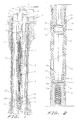
- FIGURE 2 is a sectional elevational view of a portion of the cutting tool illustrating the chemical section of the tool embodying the present invention.
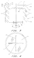
- FIGURE 3 is a sectional view of a preferred diaphragm assembly of the present invention.
- FIGURE 4 is a bottom view of the diaphragm assembly shown in FIGURE 3.
- FIGURE 5 is a side elevation in section showing another embodiment of an alternative form of diaphragm assembly.
- FIGURE 6 is a top view of a rupture diaphragm insert of the present invention.
- FIGURE 7 is a sectional view taken along lines 7-7 of FIGURE 6.
- FIGURE 8 is a perspective view of the rupture diaphragm assembly of FIGURE 6, illustrating the ruptured configuration thereof for providing a substantially full flow opening.
- Two metal diaphragms are threadedly held in a sealing configuration by a mounting device which takes the form of a cylindrical, threaded composite wedge that only sealably anchors the rupture diaphragms, but separates each pair of rupture diaphragms by an air space.
- This diaphragm assembly disclosed in the Terrell patent actually allows each rupture diaphragm to independently accomplish the sealing function as a "dual" diaphragm seal, at each end of the chemical module.
- the present invention provides an equally effective system of providing a dual diaphragm seal on one or both ends of the chemical module which is particularly well suited to small diameter cutting tools, particularly cutting tools having an outer diameter of about 3/4 inch or less which can be used for cutting small diameter tubing of about one inch.
- This is accomplished by employing a press fit diaphragm assembly into each end of the chemical module with an interference fit between the outer diameter of the diaphragm assembly and the inside diameter of the chemical module casing.
- the outside diameter of the diaphragm assembly should be .0005 to .0015 inch larger than the inside diameter of the chemical module.
- This arrangement for sealing the chemical module results in a less expensive, shorter threaded bore at each end of the chemical module.
- the press fit diaphragm is constructed without the need for threaded mounting means, resulting in significant cost savings. Since the chemical modules present a significant expense in making a cut, the present invention provides a real savings in the cost of the chemical cutting of pipe.
- FIGURE 1 of the drawings there is illustrated a chemical cutting tool embodying the present invention disposed within a well extending from the surface of the earth to a suitable subterranean location, e.g., an oil and/or gas producing formation (not shown). More particularly, and as is illustrated in FIGURE 1, a well bore 1 is provided with a casing string 2 which is cemented in place by means of a surrounding cement sheath 3. A production tubing string 4 is disposed in the well as illustrated and extends from the well head 5 to a suitable downhole location.
- the tubing string and/or the annular space 6 between the tubing and the casing may be filled with high pressure gas and/or a liquid such as oil or water.
- the tubing string 4 or the annulus 6 may be "empty", i.e., substantially at atmospheric pressure.
- FIGURE 1 there is shown a chemical cutting tool 7 which is suspended from a cable (wireline) 8.
- the cable 8 passes over suitable indicating means such as a measuring sheave 9 to a suitable support and pulley system.
- the measuring sheave produces a depth signal which is applied to an indicator 9a which gives a readout of the depth at which the tool is located.
- the well structure illustrated is exemplary only and that the cutting tool 7 can be employed in numerous other environments.
- the tool can be employed in severing a drill pipe in either a cased or uncased well.
- the tubing string 4 shown would be replaced by a string of drill pipe.
- the chemical cutter 7 is composed of five sections. At the upper end of the tool there is provided a fuse assembly 10 comprised of a fuse sub and an electrically activated fuse (not shown). Immediately below the fuse assembly 10 is a propellant section 11 which provides a source of high pressure gas.
- the propellant section 11 may take the form of a chamber containing a propellant, such as gun powder pellets, which burns to produce the propellant gases.
- a slip section 14 incorporating a slip array 15 that anchors the tool during the cutting cycle.
- a chemical module section 16 is located below the slip section 14. This section contains a suitable chemical cutting agent.
- the chemical cutting agent will take the form of a halogen fluoride, more preferably, bromine trifluoride.
- a head assembly 18 Located below the chemical module section 16 is a head assembly 18.
- This section contains an "ignitor hair" 19 such as steel wool, preferably a mixture of steel wool and alloy shavings as described below, which activates the halogen fluoride, bringing it to a temperature that will quickly cut the tubing 4.
- the head assembly 18 also contains cutting ports 20 through which the fluid is directed against the interior wall of the tubing string 4.
- the head section is equipped with the ports 20 extending about the periphery thereof to completely sever the tubing string 4 in the well.
- the port holes are arranged in a plurality of converging planar patterns generally normal to the major axis of the tool body. This arrangement greatly facilitates the severing of hard-to-cut high temperature alloy materials as described below.
- the head assembly 18 includes a bull nose sub 21 which is threadedly secured into a cutting head 18a containing the ports 20 and which is open at its lower end to provide a continuation of the central bore extending through the head assembly which is open to the well bore.
- a piston plug 22 is disposed in the central bore of the cutting head immediately above the level of the cutting ports 20. As described below, the piston plug is driven downwardly to a position below the cutting ports, and is wedged into slightly reduced diameter section of the bore as described in greater detail in the aforementioned Patent No. 4,494,601 to Pratt and Terrell.
- the operation of the chemical cutter tool 7 may be described briefly as follows.
- the tool is run into the well on the wireline 8 to the desired depth at which the cut is to be made.
- An electric signal is then sent via wireline 8 to the chemical cutter tool 7 where it sets off the fuse, in turn igniting the propellant.
- a high pressure gas is generated and travels downward through the slip section 14 and forces the slip array 15 outwardly in a manner described hereinafter.
- the slip array 15 thus anchors the chemical cutter tool 7 in the tubing string 4.
- seal diaphragms within the chemical module section 14 are ruptured and the halogen fluoride or other cutting agent is forced through the ignitor hair 19 which ignites the chemical.
- FIGURE 2 illustrates the chemical section 16 of the cutting tool in detail, illustrating two different press fit sealing assemblies 22 and 23 that function to close the bottom and top, respectively, of the chemical section 16.
- the two different types of sealing assemblies are shown in FIGURE 2 for illustrative purposes only. The assemblies need not be different and, as a practical matter, the sealing assembly 22, which usually will be preferred, can be employed to seal the top of the chemical module as well as the bottom thereof. Two variations of the preferred embodiment are shown which are the press fit sealing assemblies 22 and 23 that function as the sealable obturators for the ends of the chemical module 14.
- the press fit diaphragm assembly 22 shows a preferred form of sealing mechanism.
- the diaphragm body 24 is machined as a hollow, solid bottom, cylindrical cup comprising a tubular portion having an integral bottom portion 26 forming a rupture diaphragm 26.
- the thickness "t" of the diaphragm 26 ranges from .025 to .035 inch, where the seal body 24 is made from free machining mild steel.
- the bottom portion 26 of the seal body 24 serves as a primary rupture area for the diaphragm assembly 22.
- FIGURE 4 in conjunction with FIGURE 3, there is shown a feature of the invention to assure that the bottom portion 26 ruptures reliably at a preselected pressure value.
- the seal bottom portion 26 is weakened to facilitate rupturing by creating a reduced cross section at a central area 29 formed at the intersection of grooves which are machined linear depressions 28 and 27.
- the cross section of one of the depressions or the fossa lines 27 or 28 is shown in FIGURE 3 where "w" is the width of the depression and "d" is the depth of the depression.
- a typical depth "d” for the slots 27 and 28 would be in the range of .010 to .012 inches and a typical width "w” for the slots 27 and 28 would be in the range of .015 to .025 inch.
- a differential fluid pressure applied across the diaphragm 26 will induce a rupture due to its relative structural weakness along the lines 27 and 28 radiating outwardly to isolate triangular sections between the lines generally corresponding to the triangular sections 37 of FIGURE 8, as described below.
- the upper rupture diaphragm is formed as part of an insert body 25 having a diaphragm portion 25a and an outwardly extending ring portion 25b.
- the insert body is sealably pressed into the diaphragm retainer body 24 with .0005 to .0015 inch interference fit. That is, the outside diameter of rim diaphragm 25b is about .0005 to .0015 inch larger than the inside diameter 30 of the diaphragm retainer 24.
- the outside rim can also serve as a ferruminate weld location 30a to sealably connect the rupture diaphragm 25 of the diaphragm retainer body 24.
- Diaphragm body 25 can be arc-welded to the retainer body 24 with a fine ferruminated weld bead 30a .025 to .035 inch wide.
- o-rings 27a are installed in grooves to the retainer body 24.
- Assembly 24 effectively functions as a seal in the end of the chemical module 16 to contain a cutting fluid such as bromine trifluoride.
- the diaphragm assembly 24 normally is pressed into the chemical module 14 with an interference fit of approximately .0005 inch, although as noted above, this interference fit can vary up to .0015 inch.
- An interference fit of a somewhat greater value would cause the metal to be scored or galled, interfering with sealing capability of the o-rings 27a contained in the grooves 27 for these o-rings. In the absence of o-rings, an interference fit of greater value can be used to form a metal to metal seal.
- FIGURE 5 shows details of diaphragm assembly 23, which represents an alternative embodiment of the invention.
- two diaphragm inserts 25 are pressed into opposite ends of the tubular seal body 23a with an interference fit of .0005 to .0015 inch between the two inserts 25 and the seal body 23a.
- the two diaphragm inserts 25 are then sealably connected to seal body 23 with arc-welded fine ferruminated weld beads 30a.
- O-rings 27a are installed in each sulcus groove 27.
- diaphragm 25a includes an area of reduced cross section as shown in FIGURE 6 formed by means of grooves or depressions that forms a cross by stamping, cutting or similar fabrication technique. This effectively provides for rupture of the diaphragm at a closely preselected differential fluid pressure which is an important safety and reliability parameter.
- the pattern of the reduced cross section area is in the form of a cross having a central area 31 formed at the intersection of grooves 32 and 36.
- FIGURE 7 The area of reduced cross section is shown in cross section in FIGURE 7, wherein it can be seen that a differential fluid pressure applied across the diaphragm will induce the intersection area 31 to first initiate rupture due to its relative structural weakness in tension. The rupture will then propagate along the grooves 32 and 36, radiating outwardly to isolate avulsed triangular sections 37 and 38 as shown in FIGURE 8.
- FIGURE 8 illustrates a perspective view of a ruptured ductile diaphragm 25a with sections 37 and 38 forced downwardly along these groove lines 32 and 36 and against the side walls of the chemical module 16.
- This ruptured configuration may result from fluid flow therethrough, either gas or liquid, which fluid flow is essentially unrestricted subsequent to said rupture. Since the diaphragm 25a ruptures in tension along the aforesaid lines 32 and 36, no fragments of the rupture diaphragm are left in the chemical cutter to interfere with fluid flow.
- the upper and lower portions of the chemical section casing 16 has upper and lower interior annular shoulders 16a and 16b.
- Internally threaded connecting boxes 16c and 16d extend outwardly (upwardly in the case of 16c and downwardly in the case of 16d) away from the interior shoulders. These boxes, of course, receive the externally threaded pins from the upper and lower tool sections adjacent the chemical section.
- the tubular seal bodies 24a and 23a are provided with enlarged diameter portions 24d and 23d to provide upset shoulders 24e and 23e. The shoulders 23e and 24e rest on the interior shoulders 16a and 16b of the chemical section casing as shown in FIGURE 2.
- Each of the diaphragm bodies further comprise an annular sealing ridge 39 on the enlarged diameter portions 23d and 24d.
- a soft metal washer 39 formed of copper or the like is provided at either end of the pin connections so as to form with the rims 39 a good sealable boundary above the ferruminated weld beads 30a as shown in FIGURES 3 and 5.
- the annular ridges 39 may be offset from the top surface of the enlarged diameter portions by about .063 inch with the sides thereof at an angle of 45° with the upper enlarged portion surfaces.
Landscapes
- Life Sciences & Earth Sciences (AREA)
- Mining & Mineral Resources (AREA)
- Geology (AREA)
- Engineering & Computer Science (AREA)
- Physics & Mathematics (AREA)
- Chemical & Material Sciences (AREA)
- Environmental & Geological Engineering (AREA)
- Fluid Mechanics (AREA)
- General Chemical & Material Sciences (AREA)
- Chemical Kinetics & Catalysis (AREA)
- General Life Sciences & Earth Sciences (AREA)
- Geochemistry & Mineralogy (AREA)
- Supply Devices, Intensifiers, Converters, And Telemotors (AREA)
- Safety Valves (AREA)
Applications Claiming Priority (2)
| Application Number | Priority Date | Filing Date | Title |
|---|---|---|---|
| US07/899,628 US5322118A (en) | 1992-06-16 | 1992-06-16 | Downhole chemical cutter |
| US899628 | 1992-06-16 |
Publications (2)
| Publication Number | Publication Date |
|---|---|
| EP0575115A1 true EP0575115A1 (de) | 1993-12-22 |
| EP0575115B1 EP0575115B1 (de) | 1998-01-28 |
Family
ID=25411319
Family Applications (1)
| Application Number | Title | Priority Date | Filing Date |
|---|---|---|---|
| EP93304564A Expired - Lifetime EP0575115B1 (de) | 1992-06-16 | 1993-06-11 | Chemisches Schneidwerkzeug für Bohrlöcher |
Country Status (3)
| Country | Link |
|---|---|
| US (1) | US5322118A (de) |
| EP (1) | EP0575115B1 (de) |
| DE (1) | DE69316668T2 (de) |
Families Citing this family (11)
| Publication number | Priority date | Publication date | Assignee | Title |
|---|---|---|---|---|
| US5575331A (en) * | 1995-06-07 | 1996-11-19 | Halliburton Company | Chemical cutter |
| US6478093B1 (en) | 2000-09-29 | 2002-11-12 | Halliburton Energy Services, Inc. | Retrievable well packer apparatus and method |
| RU2227201C2 (ru) * | 2002-03-18 | 2004-04-20 | Николаев Николай Михайлович | Способ разрушения участка трубы в скважине и устройство для его осуществления |
| US6702009B1 (en) | 2002-07-30 | 2004-03-09 | Diamondback Industries, Inc. | Select-fire pressure relief subassembly for a chemical cutter |
| US20040047697A1 (en) * | 2002-09-09 | 2004-03-11 | Dara Cheng | Debris collection device for use with electrical and hand tools |
| US7278482B2 (en) * | 2004-11-22 | 2007-10-09 | Azar Ghassan R | Anchor and method of using same |
| US7661477B2 (en) * | 2006-03-31 | 2010-02-16 | Schlumberger Technology Corporation | System and method for unsticking a tool stuck in a wellbore |
| US7607478B2 (en) * | 2006-04-28 | 2009-10-27 | Schlumberger Technology Corporation | Intervention tool with operational parameter sensors |
| US7540327B2 (en) * | 2006-04-28 | 2009-06-02 | Schlumberger Technology Corporation | Abrasive jet cutting system and method for cutting wellbore tubulars |
| MX342598B (es) | 2009-12-23 | 2016-10-06 | Schlumberger Tech B V * | Colocacion hidraulica de un mecanismo de aislamiento de pozo. |
| NL2006407C2 (en) * | 2011-03-16 | 2012-09-18 | Heerema Marine Contractors Nl | Method for removing a hydrocarbon production platform from sea. |
Citations (3)
| Publication number | Priority date | Publication date | Assignee | Title |
|---|---|---|---|---|
| US4345646A (en) * | 1978-02-13 | 1982-08-24 | Gearhart Industries, Inc. | Apparatus for chemical cutting |
| EP0129331A2 (de) * | 1983-05-19 | 1984-12-27 | TRW Transportation Electronics Limited | Dehnungswandler mit Dehnungsmessstreifen |
| US4620591A (en) * | 1985-04-12 | 1986-11-04 | Gearhart Industries, Inc. | Chemical cutting apparatus having selective pressure bleed-off |
Family Cites Families (8)
| Publication number | Priority date | Publication date | Assignee | Title |
|---|---|---|---|---|
| US2918125A (en) * | 1955-05-09 | 1959-12-22 | William G Sweetman | Chemical cutting method and apparatus |
| GB1565004A (en) * | 1977-04-18 | 1980-04-16 | Weatherford Dmc | Chemical cutting appratus and method for use in wells |
| US4315797A (en) * | 1980-06-02 | 1982-02-16 | Gearhart Industries, Inc. | Chemical pipe cutter with exponential spacing between reactant stages |
| US4613394A (en) * | 1980-09-02 | 1986-09-23 | Gearhart Industries, Inc. | Staged chemical pipe cutter |
| US4415029A (en) * | 1981-07-23 | 1983-11-15 | Gearhart Industries, Inc. | Downhole well tool and anchoring assembly |
| US4494601A (en) * | 1981-09-14 | 1985-01-22 | Gearhart Industries, Inc. | Downhole chemical cutting tool |
| US4619318A (en) * | 1984-09-27 | 1986-10-28 | Gearhart Industries, Inc. | Chemical cutting method and apparatus |
| US4971146A (en) * | 1988-11-23 | 1990-11-20 | Terrell Jamie B | Downhole chemical cutting tool |
-
1992
- 1992-06-16 US US07/899,628 patent/US5322118A/en not_active Expired - Fee Related
-
1993
- 1993-06-11 DE DE69316668T patent/DE69316668T2/de not_active Expired - Fee Related
- 1993-06-11 EP EP93304564A patent/EP0575115B1/de not_active Expired - Lifetime
Patent Citations (3)
| Publication number | Priority date | Publication date | Assignee | Title |
|---|---|---|---|---|
| US4345646A (en) * | 1978-02-13 | 1982-08-24 | Gearhart Industries, Inc. | Apparatus for chemical cutting |
| EP0129331A2 (de) * | 1983-05-19 | 1984-12-27 | TRW Transportation Electronics Limited | Dehnungswandler mit Dehnungsmessstreifen |
| US4620591A (en) * | 1985-04-12 | 1986-11-04 | Gearhart Industries, Inc. | Chemical cutting apparatus having selective pressure bleed-off |
Also Published As
| Publication number | Publication date |
|---|---|
| US5322118A (en) | 1994-06-21 |
| DE69316668D1 (de) | 1998-03-05 |
| EP0575115B1 (de) | 1998-01-28 |
| DE69316668T2 (de) | 1998-06-18 |
Similar Documents
| Publication | Publication Date | Title |
|---|---|---|
| US4494601A (en) | Downhole chemical cutting tool | |
| EP0575116A1 (de) | Chemisches Schneidwerkzeug für Bohrlöcher und Verfahren | |
| US5575331A (en) | Chemical cutter | |
| US4345646A (en) | Apparatus for chemical cutting | |
| US7328750B2 (en) | Sealing plug and method for removing same from a well | |
| US4619318A (en) | Chemical cutting method and apparatus | |
| US4415029A (en) | Downhole well tool and anchoring assembly | |
| US3766979A (en) | Well casing cutter and sealer | |
| EP0575114B1 (de) | Chemisches Grosskopf-Schneidwerkzeug für Bohrlöcher | |
| CA2947021C (en) | Devices and related methods for actuating wellbore tools with a pressurized gas | |
| US4352397A (en) | Methods, apparatus and pyrotechnic compositions for severing conduits | |
| EP1998001B1 (de) | Perforierbrennvorrichtung und Verfahren | |
| US7533727B2 (en) | Oil well completion tool having severable tubing string barrier disc | |
| US5322118A (en) | Downhole chemical cutter | |
| US4620591A (en) | Chemical cutting apparatus having selective pressure bleed-off | |
| EP1875040B1 (de) | Stimulationsgerät mit versiegeltem zündsystem | |
| US4323117A (en) | Method and means for emergency shearing and sealing of well casing | |
| US9255459B2 (en) | Collapsible casing device for use in controlling flow | |
| CA1148852A (en) | Chemical cutting apparatus | |
| CA3132931A1 (en) | Non-mechanical ported perforating torch | |
| CA1184843A (en) | Apparatus for chemical cutting | |
| GB2124678A (en) | Apparatus for chemical cutting | |
| US11821291B2 (en) | Perforating torch apparatus and method | |
| CA1170163A (en) | Apparatus for chemical cutting |
Legal Events
| Date | Code | Title | Description |
|---|---|---|---|
| PUAI | Public reference made under article 153(3) epc to a published international application that has entered the european phase |
Free format text: ORIGINAL CODE: 0009012 |
|
| AK | Designated contracting states |
Kind code of ref document: A1 Designated state(s): DE DK FR GB NL |
|
| 17P | Request for examination filed |
Effective date: 19940607 |
|
| 17Q | First examination report despatched |
Effective date: 19960301 |
|
| GRAG | Despatch of communication of intention to grant |
Free format text: ORIGINAL CODE: EPIDOS AGRA |
|
| GRAG | Despatch of communication of intention to grant |
Free format text: ORIGINAL CODE: EPIDOS AGRA |
|
| GRAH | Despatch of communication of intention to grant a patent |
Free format text: ORIGINAL CODE: EPIDOS IGRA |
|
| GRAH | Despatch of communication of intention to grant a patent |
Free format text: ORIGINAL CODE: EPIDOS IGRA |
|
| GRAA | (expected) grant |
Free format text: ORIGINAL CODE: 0009210 |
|
| AK | Designated contracting states |
Kind code of ref document: B1 Designated state(s): DE DK FR GB NL |
|
| REF | Corresponds to: |
Ref document number: 69316668 Country of ref document: DE Date of ref document: 19980305 |
|
| ET | Fr: translation filed | ||
| PG25 | Lapsed in a contracting state [announced via postgrant information from national office to epo] |
Ref country code: DK Free format text: LAPSE BECAUSE OF FAILURE TO SUBMIT A TRANSLATION OF THE DESCRIPTION OR TO PAY THE FEE WITHIN THE PRESCRIBED TIME-LIMIT Effective date: 19980428 |
|
| PLBE | No opposition filed within time limit |
Free format text: ORIGINAL CODE: 0009261 |
|
| STAA | Information on the status of an ep patent application or granted ep patent |
Free format text: STATUS: NO OPPOSITION FILED WITHIN TIME LIMIT |
|
| PGFP | Annual fee paid to national office [announced via postgrant information from national office to epo] |
Ref country code: NL Payment date: 19981231 Year of fee payment: 6 |
|
| 26N | No opposition filed | ||
| PGFP | Annual fee paid to national office [announced via postgrant information from national office to epo] |
Ref country code: DE Payment date: 19990614 Year of fee payment: 7 |
|
| PGFP | Annual fee paid to national office [announced via postgrant information from national office to epo] |
Ref country code: FR Payment date: 19990917 Year of fee payment: 7 |
|
| PGFP | Annual fee paid to national office [announced via postgrant information from national office to epo] |
Ref country code: GB Payment date: 19990920 Year of fee payment: 7 |
|
| PG25 | Lapsed in a contracting state [announced via postgrant information from national office to epo] |
Ref country code: NL Free format text: LAPSE BECAUSE OF NON-PAYMENT OF DUE FEES Effective date: 20000101 |
|
| NLV4 | Nl: lapsed or anulled due to non-payment of the annual fee |
Effective date: 20000101 |
|
| PG25 | Lapsed in a contracting state [announced via postgrant information from national office to epo] |
Ref country code: GB Free format text: LAPSE BECAUSE OF NON-PAYMENT OF DUE FEES Effective date: 20000611 |
|
| GBPC | Gb: european patent ceased through non-payment of renewal fee |
Effective date: 20000611 |
|
| PG25 | Lapsed in a contracting state [announced via postgrant information from national office to epo] |
Ref country code: FR Free format text: LAPSE BECAUSE OF NON-PAYMENT OF DUE FEES Effective date: 20010228 |
|
| REG | Reference to a national code |
Ref country code: FR Ref legal event code: ST |
|
| PG25 | Lapsed in a contracting state [announced via postgrant information from national office to epo] |
Ref country code: DE Free format text: LAPSE BECAUSE OF NON-PAYMENT OF DUE FEES Effective date: 20010403 |