EP0575196A1 - Filtre pour carburant pourvu d'un système de dégazage integré - Google Patents
Filtre pour carburant pourvu d'un système de dégazage integré Download PDFInfo
- Publication number
- EP0575196A1 EP0575196A1 EP93304789A EP93304789A EP0575196A1 EP 0575196 A1 EP0575196 A1 EP 0575196A1 EP 93304789 A EP93304789 A EP 93304789A EP 93304789 A EP93304789 A EP 93304789A EP 0575196 A1 EP0575196 A1 EP 0575196A1
- Authority
- EP
- European Patent Office
- Prior art keywords
- fuel
- passage
- conduit
- filter
- defining
- Prior art date
- Legal status (The legal status is an assumption and is not a legal conclusion. Google has not performed a legal analysis and makes no representation as to the accuracy of the status listed.)
- Granted
Links
- 239000000446 fuel Substances 0.000 title claims abstract description 149
- 238000004891 communication Methods 0.000 claims abstract description 14
- 239000012530 fluid Substances 0.000 claims abstract description 8
- 238000007789 sealing Methods 0.000 claims description 9
- 238000001914 filtration Methods 0.000 claims description 8
- 238000005192 partition Methods 0.000 claims 2
- 230000015572 biosynthetic process Effects 0.000 abstract description 11
- XLYOFNOQVPJJNP-UHFFFAOYSA-N water Substances O XLYOFNOQVPJJNP-UHFFFAOYSA-N 0.000 description 10
- 238000002485 combustion reaction Methods 0.000 description 3
- 239000002283 diesel fuel Substances 0.000 description 3
- 230000009977 dual effect Effects 0.000 description 3
- 238000010348 incorporation Methods 0.000 description 3
- 230000000694 effects Effects 0.000 description 2
- 230000037406 food intake Effects 0.000 description 2
- 238000002347 injection Methods 0.000 description 2
- 239000007924 injection Substances 0.000 description 2
- 239000002245 particle Substances 0.000 description 2
- 239000013618 particulate matter Substances 0.000 description 2
- 238000010521 absorption reaction Methods 0.000 description 1
- 230000006978 adaptation Effects 0.000 description 1
- 230000002411 adverse Effects 0.000 description 1
- 238000004873 anchoring Methods 0.000 description 1
- 230000000712 assembly Effects 0.000 description 1
- 238000000429 assembly Methods 0.000 description 1
- 230000004888 barrier function Effects 0.000 description 1
- 230000000740 bleeding effect Effects 0.000 description 1
- 238000010276 construction Methods 0.000 description 1
- 238000012986 modification Methods 0.000 description 1
- 230000004048 modification Effects 0.000 description 1
- 239000011236 particulate material Substances 0.000 description 1
- 230000000717 retained effect Effects 0.000 description 1
Images
Classifications
-
- B—PERFORMING OPERATIONS; TRANSPORTING
- B01—PHYSICAL OR CHEMICAL PROCESSES OR APPARATUS IN GENERAL
- B01D—SEPARATION
- B01D27/00—Cartridge filters of the throw-away type
- B01D27/08—Construction of the casing
-
- B—PERFORMING OPERATIONS; TRANSPORTING
- B01—PHYSICAL OR CHEMICAL PROCESSES OR APPARATUS IN GENERAL
- B01D—SEPARATION
- B01D27/00—Cartridge filters of the throw-away type
- B01D27/14—Cartridge filters of the throw-away type having more than one filtering element
- B01D27/146—Cartridge filters of the throw-away type having more than one filtering element connected in series
- B01D27/148—Cartridge filters of the throw-away type having more than one filtering element connected in series arranged concentrically or coaxially
-
- B—PERFORMING OPERATIONS; TRANSPORTING
- B01—PHYSICAL OR CHEMICAL PROCESSES OR APPARATUS IN GENERAL
- B01D—SEPARATION
- B01D36/00—Filter circuits or combinations of filters with other separating devices
- B01D36/001—Filters in combination with devices for the removal of gas, air purge systems
-
- B—PERFORMING OPERATIONS; TRANSPORTING
- B01—PHYSICAL OR CHEMICAL PROCESSES OR APPARATUS IN GENERAL
- B01D—SEPARATION
- B01D36/00—Filter circuits or combinations of filters with other separating devices
- B01D36/003—Filters in combination with devices for the removal of liquids
-
- B—PERFORMING OPERATIONS; TRANSPORTING
- B01—PHYSICAL OR CHEMICAL PROCESSES OR APPARATUS IN GENERAL
- B01D—SEPARATION
- B01D2201/00—Details relating to filtering apparatus
- B01D2201/34—Seals or gaskets for filtering elements
Definitions
- This invention relates generally to filters for filtering and separating fluids. More particularly, the present invention relates to fuel filters for removing foreign particles and separating water from the fuel of the fuel supply system of an internal combustion engine.
- U.S. Patent No. 4,976,852 and U.S. Patent No. 5,084,170 which are assigned to the assignee of the present invention, disclose fuel filter assemblies to which the present invention relates.
- the fuel filters employ a base which mounts a disposable filter cartridge.
- the cartridge includes a dual stage filter system wherein fuel flows axially to a primary filter element for removing particulate matter and coalescing water droplets and axially to a second filter stage which functions as a water barrier. Filtered fuel flows axially and exits through an outlet passage of the base. The water may be collected in a sump and periodically removed.
- the cartridge is secured to the base by a collar which engages against a roll seam structure of the cartridge.
- air pockets are present in the fuel filter as fuel circulates through the fuel filter.
- the air pockets normally form at the top of the fuel filter. Air bubbles tend to form in the fuel circulating through the filter due to the air pockets.
- the air pockets tend to disintegrate over time and/or the stream of bubbles present in the fuel is of a relatively small magnitude.
- the air pockets do not result in the formation of large air bubbles in the fuel supply partly due to the vapor pressure of the pressurized fuel. Consequently, for pressurized systems, air pockets in the fuel filter do not present a significant problem or obstacle to the circulation of fuel through the fuel filter and the delivery of fuel to the engine.
- the formation of air pockets in the fuel circulating through the filter can present a more significant problem.
- the air pockets are much more resistant to absorption over time in vacuum systems.
- the vacuum suction exerted on the fuel tends to result in ingestion of larger air bubbles which can become an obstacle to uniform fuel delivery to the engine.
- the air pockets may grow as a result of changing levels of fuel within the filter. The fuel level changes may be caused by vehicle manoeuvring, such as turning, which produces centrifugal forces that result in sloshing of fuel within the filter.
- the air pockets within the filter may also enlarge over time under a vacuum system. Vacuum systems tend to be more susceptible to the ingestion into the fuel delivery stream of an air bubble which has a magnitude sufficient to produce a subsequent engine sputter.
- a fuel filter assembly comprising a fuel inlet connected to a first passage, a fuel outlet connected to a second passage disposed around said first passage, means defining a flow path between said first and second passages, and a filter disposed in said flow path, wherein a vent orifice is provided in said second passage and arranged such that excess air in the filter is bled via said vent orifice into said second passage.
- the invention provides a fuel filter assembly which incorporates an internal vent to control air bubble formation and its adverse effects.
- the invention implements a bleed path within the filter to control the formation of air bubbles in the fuel supply exiting the filter.
- the fuel filter includes a base which has a fuel inlet and a fuel outlet.
- a second conduit surrounds the first conduit and defines a second axial passage.
- the second axial passage communicates with the outlet.
- a vent orifice opens radially through the second conduit.
- the orifice is dimensioned and located to limit the formation of air bubbles to a controlled magnitude.
- the filter cartridge which is mountable to the base, includes at least one filter element.
- a fuel circulation path which traverses the element communicates between the first axial passage and the second axial passage.
- a fuel filter assembly comprising: base means comprising a base having a fuel inlet, a fuel outlet, first conduit means for interiorly defining a first passage which extends along a first axis, first path means for providing fuel communication between said first passage and said inlet, second conduit means surrounding said first conduit means for defining a second passage having a generally uniform outer diameter, second path means for providing fuel communication between said second passage and said outlet, said second conduit means comprising vent means for defining a vent orifice; filter cartridge means mounted on said base means for filtering fuel, said cartridge means comprising a housing having an end portion defining an opening for said first and second conduit means and seal means for sealing said end portion with said second conduit means along a seal interface which is axially spaced from said vent orifice no greater than one-half the diameter of said second passage, said cartridge means comprising at least one filter element and circulation path means defining a fuel path communicating with said first passage and said second passage and traversing said element; and retainer means for retaining said
- a fuel filter assembly comprising: base means comprising a base having a fuel inlet, a fuel outlet, a first conduit defining a first passage communicable with said inlet and extending along a first axis, a second conduit surrounding said first conduit for defining a second passage communicable with said outlet, said second conduit having an opening and orifice means defining an orifice axially spaced from said opening; filter cartridge means comprising a housing having an end portion defining a second opening for receiving said first and second conduits, said cartridge means being mountable on said base means for filtering fuel, said cartridge means comprising primary filter means enclosed in said housing and comprising a primary filter element defining a first chamber communicable with said first passage and a second chamber surrounding said first chamber, said cartridge means comprising secondary filter means comprising a secondary filter element defining a third chamber communicable with said second passage and seal means for sealing said second conduit means with said end portion when said cartridge means is mounted to said base means, wherein
- a fuel filter assembly further comprising: base means comprising a base having said fuel inlet and said fuel outlet provided therein, first conduit means for interiorly defining said first passage, first path means for providing fuel communication between said first passage and said inlet, second conduit means for defining said second passage extending along a central axis, second path means for providing fuel communication between said second axial passage and said outlet, said second conduit means axially terminating in an opening, said second conduit means comprising a plurality of orifice means for defining orifices equidistantly axially spaced from said opening; and said filter comprising filter cartridge means mountable on said base means for filtering fuel, said cartridge means comprising at least one filter element and circulation path means defining a fuel path communicating with said first passage and said second axial passage and traversing said element, said cartridge means having a chamber partially defined by said at least one filter element, which chamber fluidically communicates with said second axial passage via said opening and at least one said orifice defines a
- the second conduit has a plurality of orifices which substantially axially align.
- the orifices may have a diameter of approximately 0.050 inches.
- the orifice or orifices define a bleed path between an interiorly formed chamber of the cartridge and an upper portion of the second axial passage.
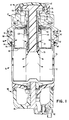
- Fuel filter assembly 10 comprises a base 12 and a disposable filter cartridge 14.
- the base 12 is disposed generally above the disposable filter cartridge 14 which is locked to the base by means of a retainer collar 16.
- the fuel filter assembly is especially adapted for incorporation into the fuel supply system of an internal combustion engine (not illustrated), such as a diesel engine, for removing particulate matter from fuel and separating the water from the fuel.
- the fuel filter assembly 10 is particularly adapted for incorporation into a fuel supply system which is operated under a vacuum.
- the base 12 and the disposable cartridge 14 may assume a wide variety of configurations.
- the base is an inverted cup-like receptacle which forms a skirt defining a lower receiving cavity for upper portions of a disposable cartridge.
- a central stepped axial bore 22 in the base closely receives an elongated sleeve-like conduit 24 and an outer concentric sleeve-like conduit 26 having an axial end 27.
- the conduits provide generally coaxial fluid communication between the base and the disposable cartridge.
- an inlet connector 30 at an upper side location of the base connects with the fuel line (not illustrated) to ultimately provide fluid communication through the interior passageway defined by the first conduit 24.
- An outlet connector 32 at an upper-side location of the base connects with the fuel line to provide external fluid communication from the axial fluid conduit defined between the first and second conduits 24 and 26.
- An integral projecting bracket 40 which may include a pair of openings 42, 44 for anchoring the filter base to the engine header extends transversely from the base.
- the base may not employ the described bracket structure but instead include a pair of fastener openings for receiving mounting fasteners.
- the base may also have an external air vent 46.
- the disposable filter cartridge 14 comprises a can-like enclosure formed by a pair of opposed lower and upper cup-like sections 52, 54. The sections are joined along a circumferential roll seam 60.
- the upper section 52 which is smaller in diameter than the lower section, is received by the base receptacle.
- the upper section 52 is dimensioned to be closely accommodated in the base receptacle.
- a central axial opening 56 in the upper section is dimensioned to receive the conduits 24 and 26.
- a sealing grommet 58 mounted at the opening 56 diametrically fluidically seals against the outer conduit 26.
- the cartridge may employ a single stage filter assembly or a dual stage assembly as illustrated in Figure 1.
- a secondary filter element 64 which has a continuous fan-shaped pleated configuration is mounted in the upper section. The lower end of the secondary element 64 is engaged by a multi-folded medial plate 68 having a central opening.
- a second sealing grommet 70 mounted at the opening diametrically seals against the first conduit 24.
- a primary filter element 72 also has a continuous fan-like configuration which engages the underside of the medial plate. The primary filter element 72 is housed in the lower section 54. A sump is formed at the bottom of the lower section to collect water which coalesces from the fuel.
- a modular bowl assembly generally designated by the numeral 80 is mounted at a lower portion of the cartridge for collecting the water from the sump.
- a drain-cock 82 is disposed in the lower portion of a collection bowl 84 for draining the water from the collection bowl 84.
- the collection bowl 84 may be identical in form and function to that described in copending U.S. Patent Application Serial No. 07/748,775 filed on August 22, 1991, which application is assigned to the assignee of the present invention and the disclosure of which is incorporated herein by reference.
- the base may include a pair of integral outwardly projecting diametrically opposed ramps 90 and 92.
- the ramps ascend in spiral-like fashion around the base.
- the upper ends of the ramps are bevelled.
- the collar includes a pair of diametrically disposed spiral followers 94 and 96 which integrally extend inwardly from the collar.
- the followers 94, 96 are dimensioned and positioned for engagement with the ramps 90, 92 so that the followers slidably engage and ascend the ramps upon alignment and angular rotation of the collar.
- a positive lock position is releasably maintained by the force of a spring 100 which is mounted to the base.
- the spring is retained by an integral crimped positioning ring 102 of the outer conduit 26.
- the foregoing ramp and spring configuration may be substantially identical to that disclosed in copending U.S. Patent Application Serial No. 07/746,693 filed on August 16, 1991, which application is assigned to the assignee of the present invention and the disclosure of which is incorporated herein by reference.
- the collar 16 includes an inwardly projecting annular shoulder 61 which engages the roll seam 60 of the cartridge for releasably locking the cartridge to the base.
- a plug may also be secured by a cap 112 in an upper cavity of the base.
- the plug extends axially into the first conduit 24 and includes radial grooves 114 for directing the flow of fuel from the inlet 30 to the first conduit 24.
- the plug assembly may be substantially identical to that disclosed in copending U.S. Patent Application Serial No. 07/745,871 filed on August 16, 1991, which application is assigned to the assignee of the present invention and the disclosure of which is incorporated herein by reference.
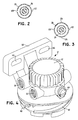
- the conduit 26 has at least one orifice 120 which functions as a bleed vent to control the formation of air bubbles in the fuel exiting the fuel filter assembly via the conduit 26.
- the orifice 120 has a diameter of approximately 0.050 inches.
- the orifice 120 is preferably located just below the sealing interface of sealing grommet 58.
- the axial distance of the orifice 120 from conduit end 27 is preferably at least equal to one half of the inner diameter of conduit 26.
- the fuel enters the fuel filter assembly through the fuel inlet passage and exits the filter through the outlet passage.
- the general flow path of the fuel through the filter assembly is generally designated by the Figure 1 arrows. It will be appreciated that the fuel flow path initially axially traverses through the interior of the inner conduit 24 and generally outwardly through the primary filter 72.
- the circulation path extends generally axially upwardly and generally radially through the secondary filter element with the return flow path traversing between the inner conduit 24 and the outer conduit 26.
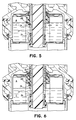
- the orifice 120 functions as a bleed vent to control the formation of air bubbles in the return fuel flow path particularly as the level of the fuel in the filter changes.
- a vacuum head draws fuel upwardly through the return passageway between conduits 24 and 26. If the level of fuel descends to a position which at least partially uncovers orifice 120 such as illustrated in Figure 6, air will bleed in a controlled fashion through the orifice into the filtered fuel traversing the return passageway.
- the intermittent stream of air bubbles B will have no or a negligible effect on the delivery of fuel since the bubbles B will be relatively small in size.
- the bleed path provided by the orifice 120 functions to prevent a large "gulp" of air entering or being ingested into the fuel stream at the lower axial end of conduit 26 and to thus prevent the air bubble formation which cannot be easily consumed by the fuel injection pump.
- the orifice 120 also functions to prevent the formation of a large air pocket above the fuel level by providing the air bleed to the return passage.
- Additional axially aligned and angularly spaced orifices 122, 124 and 126 may be provided in the conduit 26 as illustrated in Figures 2 and 3. These additional orifices function in substantially the same manner described for orifice 120.
- the invention provides a new and improved fuel filter adaptable for use in filtering fuel supplied to an internal combustion engine.
- the invention provides a new and improved fuel filter of efficient low cost construction which is especially adapted for incorporation into a fuel supply system which operates under a vacuum.
- preferred embodiments of the invention provide a new and improved fuel filter which employs a disposable cartridge incorporating improved means for controlling the formation of air bubbles in the fuel supply exiting the filter.
Landscapes
- Chemical & Material Sciences (AREA)
- Chemical Kinetics & Catalysis (AREA)
- Filtration Of Liquid (AREA)
Applications Claiming Priority (2)
| Application Number | Priority Date | Filing Date | Title |
|---|---|---|---|
| US90011692A | 1992-06-18 | 1992-06-18 | |
| US900116 | 1992-06-18 |
Publications (2)
| Publication Number | Publication Date |
|---|---|
| EP0575196A1 true EP0575196A1 (fr) | 1993-12-22 |
| EP0575196B1 EP0575196B1 (fr) | 1998-09-09 |
Family
ID=25411994
Family Applications (1)
| Application Number | Title | Priority Date | Filing Date |
|---|---|---|---|
| EP93304789A Expired - Lifetime EP0575196B1 (fr) | 1992-06-18 | 1993-06-18 | Filtre pour carburant pourvu d'un système de dégazage integré |
Country Status (4)
| Country | Link |
|---|---|
| US (1) | US5413711A (fr) |
| EP (1) | EP0575196B1 (fr) |
| JP (1) | JP3373597B2 (fr) |
| DE (1) | DE69320874T2 (fr) |
Cited By (9)
| Publication number | Priority date | Publication date | Assignee | Title |
|---|---|---|---|---|
| EP0699834A1 (fr) | 1994-09-02 | 1996-03-06 | Lucas Industries Public Limited Company | Filtre de carburant |
| EP0579484B1 (fr) * | 1992-07-17 | 1997-03-05 | LUCAS INDUSTRIES public limited company | Filtre |
| DE19639283A1 (de) * | 1996-09-25 | 1998-03-26 | Knecht Filterwerke Gmbh | Kraftstoffilter, insbesondere Dieselkraftstoffilter |
| EP0852158A1 (fr) * | 1997-01-06 | 1998-07-08 | Baldwin Filters, Inc. | Filtre primaire/secondaire de carburant avec deux media différents |
| GB2329850A (en) * | 1997-10-03 | 1999-04-07 | Lucas Ind Plc | Liquid filter with slot shaped air vent |
| FR2819546A1 (fr) * | 2001-01-16 | 2002-07-19 | Filtrauto | Boitier de filtre a etancheite axiale et radiale |
| WO2009095339A1 (fr) * | 2008-02-01 | 2009-08-06 | Mann+Hummel Gmbh | Filtre à liquides notamment destiné à du carburant |
| EP2969105A4 (fr) * | 2013-03-15 | 2016-11-16 | Clarcor Engine Mobile Solutions Llc | Cartouche de filtre composite |
| EP3147016A1 (fr) * | 2015-09-22 | 2017-03-29 | Caterpillar Inc. | Élément filtrant et ensemble filtrant destinés à séparer des fluides |
Families Citing this family (35)
| Publication number | Priority date | Publication date | Assignee | Title |
|---|---|---|---|---|
| US5484527A (en) * | 1993-12-13 | 1996-01-16 | Stanadyne Automotive Corp. | Module for filter assembly base |
| US6378907B1 (en) * | 1996-07-12 | 2002-04-30 | Mykrolis Corporation | Connector apparatus and system including connector apparatus |
| US6293410B1 (en) * | 1999-06-29 | 2001-09-25 | Mahle-Parr Filter Systems, Inc. | No-cure fuel filter and method for making same |
| US6270659B1 (en) | 1999-07-02 | 2001-08-07 | Fleetguard, Inc. | Fuel filtering system for an engine |
| ATE446800T1 (de) | 2000-05-12 | 2009-11-15 | Pall Corp | Filter |
| DE60117260T2 (de) | 2000-05-12 | 2006-10-05 | Pall Corp. | Filtrationssysteme |
| JP2004508183A (ja) * | 2000-09-13 | 2004-03-18 | マイクロリス・コーポレイシヨン | 液体濾過装置 |
| US7469932B2 (en) * | 2001-09-13 | 2008-12-30 | Entegris, Inc. | Receptor for a separation module |
| JP4731811B2 (ja) * | 2001-09-13 | 2011-07-27 | インテグリス・インコーポレーテッド | 分離モジュールおよび固定レセプターを備えたシステムならびに分離モジュール |
| DE10220662B4 (de) * | 2002-05-10 | 2005-08-11 | Hydraulik-Ring Gmbh | Filterpatrone für flüssige, einfriergefährdete Medien, insbesondere für den Einsatz bei Brennstoffzellenfahrzeugen und bei Verbrennungskraftmaschinen, vorzugsweise Dieselmotoren |
| KR101107442B1 (ko) * | 2003-08-01 | 2012-01-19 | 파커-한니핀 코포레이션 | 통기 필터 요소를 구비한 필터 조립체 |
| DE102004025062B4 (de) * | 2004-05-18 | 2006-09-14 | Hydraulik-Ring Gmbh | Gefriertaugliches Dosierventil |
| EP2471587B1 (fr) * | 2005-07-22 | 2017-02-01 | Mann + Hummel GmbH | Filtre à carburant |
| US8114285B2 (en) * | 2006-05-24 | 2012-02-14 | Parker-Hannifin Corporation | Tri-flow filter element with venting |
| DE102006051406A1 (de) * | 2006-10-27 | 2008-04-30 | Mann + Hummel Gmbh | Kraftstofffilter |
| DE102007055841A1 (de) | 2006-12-27 | 2008-07-03 | Denso Corp., Kariya | Kraftstofffiltervorrichtung, Kraftstoffzufuhrgerät und Verfahren zum Filtern von Kraftstoff |
| DE202007000746U1 (de) * | 2007-01-12 | 2008-05-21 | Mann+Hummel Gmbh | Kraftstofffilter |
| DE102007004687B4 (de) * | 2007-01-25 | 2012-03-01 | Hydraulik-Ring Gmbh | Volumensmengenabgabeeinheit und Verfahren zur Kalibrierung der Druckausgangssignal-Volumensmenge-Charakteristik |
| US7779818B2 (en) * | 2007-07-12 | 2010-08-24 | Caterpillar Inc. | System and method for priming a fluid system |
| US8147691B2 (en) * | 2007-09-21 | 2012-04-03 | Baldwin Filters, Inc. | Filter cartridge housing attachment systems |
| DE102008012780B4 (de) | 2008-03-05 | 2012-10-04 | Hydraulik-Ring Gmbh | Abgasnachbehandlungseinrichtung |
| US7827971B2 (en) * | 2009-01-26 | 2010-11-09 | Gm Global Technology Operations, Inc. | Engine assembly with fuel filter gas removal apparatus |
| US20110017649A1 (en) * | 2009-07-24 | 2011-01-27 | Sasur Timothy M | Two stage filter cartridge |
| DE102009035940C5 (de) * | 2009-08-03 | 2017-04-20 | Cummins Ltd. | SCR-Abgasnachbehandlungseinrichtung |
| DE102010027785B4 (de) * | 2010-04-15 | 2020-12-03 | Hengst Se | Ölnebelabscheider mit einem Gehäuse mit abnehmbarem Deckel |
| DE102010061222B4 (de) | 2010-12-14 | 2015-05-07 | Cummins Ltd. | SCR-Abgasnachbehandlungseinrichtung |
| US9700818B2 (en) * | 2010-12-30 | 2017-07-11 | Baldwin Filters, Inc. | Vented liquid filter vented through media |
| US9028702B2 (en) | 2011-09-20 | 2015-05-12 | Baldwin Filters, Inc. | Fuel filter with snorkel vent |
| US9051906B2 (en) | 2012-02-29 | 2015-06-09 | Ford Global Technologies, Llc | Diesel fuel system conditioning |
| US9089791B2 (en) | 2013-03-14 | 2015-07-28 | Cummins Ip, Inc. | Apparatus, method, and system for reductant filtration |
| US11035330B2 (en) * | 2015-10-16 | 2021-06-15 | MANN+HUMMEL Filtration Technology Group Inc. | Filter element with air-bleed conduit |
| US10807026B2 (en) | 2015-10-16 | 2020-10-20 | MANN+HUMMEL Filtration Technology US LLC | Filter element with air-bleed conduit |
| WO2018067437A1 (fr) | 2016-10-03 | 2018-04-12 | Parker-Hannifin Corporation | Élément de filtre avec verrou de torsion et ensemble |
| CN110769913B (zh) | 2017-05-31 | 2021-11-16 | 帕克-汉尼芬公司 | 带有扭锁和/或滑动活塞的过滤元件、组件和方法 |
| USD958931S1 (en) * | 2020-08-26 | 2022-07-26 | Wuhu TianHao E-commerce CO., LTD. | Oil water separator with replaceable filter |
Citations (4)
| Publication number | Priority date | Publication date | Assignee | Title |
|---|---|---|---|---|
| FR1385489A (fr) * | 1963-11-22 | 1965-01-15 | Prec Mecanique Labinal | Perfectionnements aux filtres et séparateurs de liquides |
| US3695443A (en) * | 1970-08-20 | 1972-10-03 | Industrial Filter Pump Mfg Co | Filter apparatus |
| WO1991003301A1 (fr) * | 1989-09-08 | 1991-03-21 | Stanadyne Automotive Corp. | Filtre a carburant |
| EP0517410A1 (fr) * | 1991-06-04 | 1992-12-09 | Lucas Industries Public Limited Company | Filtre |
Family Cites Families (4)
| Publication number | Priority date | Publication date | Assignee | Title |
|---|---|---|---|---|
| US3234064A (en) * | 1962-06-20 | 1966-02-08 | Motor Trims Pty Ltd | Method of forming a composite sandwich type panel |
| JPS4810746B1 (fr) * | 1970-05-19 | 1973-04-06 | ||
| US5017285A (en) * | 1989-06-28 | 1991-05-21 | Stanadyne Automotive Corp. | Fuel filter and cartridge assembly |
| US4976852A (en) * | 1989-06-28 | 1990-12-11 | Stanadyne Automotive Corp. | Fuel filter |
-
1993
- 1993-06-14 JP JP16749293A patent/JP3373597B2/ja not_active Expired - Lifetime
- 1993-06-18 DE DE69320874T patent/DE69320874T2/de not_active Expired - Fee Related
- 1993-06-18 EP EP93304789A patent/EP0575196B1/fr not_active Expired - Lifetime
- 1993-11-19 US US08/155,101 patent/US5413711A/en not_active Expired - Lifetime
Patent Citations (4)
| Publication number | Priority date | Publication date | Assignee | Title |
|---|---|---|---|---|
| FR1385489A (fr) * | 1963-11-22 | 1965-01-15 | Prec Mecanique Labinal | Perfectionnements aux filtres et séparateurs de liquides |
| US3695443A (en) * | 1970-08-20 | 1972-10-03 | Industrial Filter Pump Mfg Co | Filter apparatus |
| WO1991003301A1 (fr) * | 1989-09-08 | 1991-03-21 | Stanadyne Automotive Corp. | Filtre a carburant |
| EP0517410A1 (fr) * | 1991-06-04 | 1992-12-09 | Lucas Industries Public Limited Company | Filtre |
Cited By (15)
| Publication number | Priority date | Publication date | Assignee | Title |
|---|---|---|---|---|
| EP0579484B1 (fr) * | 1992-07-17 | 1997-03-05 | LUCAS INDUSTRIES public limited company | Filtre |
| EP0699834A1 (fr) | 1994-09-02 | 1996-03-06 | Lucas Industries Public Limited Company | Filtre de carburant |
| US5665230A (en) * | 1994-09-02 | 1997-09-09 | Lucas Industries Public Limited Company | Fuel filter |
| EP0699834B1 (fr) * | 1994-09-02 | 1999-01-20 | Lucas Industries Public Limited Company | Filtre de carburant |
| DE19639283A1 (de) * | 1996-09-25 | 1998-03-26 | Knecht Filterwerke Gmbh | Kraftstoffilter, insbesondere Dieselkraftstoffilter |
| EP0852158A1 (fr) * | 1997-01-06 | 1998-07-08 | Baldwin Filters, Inc. | Filtre primaire/secondaire de carburant avec deux media différents |
| GB2329850A (en) * | 1997-10-03 | 1999-04-07 | Lucas Ind Plc | Liquid filter with slot shaped air vent |
| FR2819546A1 (fr) * | 2001-01-16 | 2002-07-19 | Filtrauto | Boitier de filtre a etancheite axiale et radiale |
| WO2009095339A1 (fr) * | 2008-02-01 | 2009-08-06 | Mann+Hummel Gmbh | Filtre à liquides notamment destiné à du carburant |
| EP2969105A4 (fr) * | 2013-03-15 | 2016-11-16 | Clarcor Engine Mobile Solutions Llc | Cartouche de filtre composite |
| US10940409B2 (en) | 2013-03-15 | 2021-03-09 | Parker-Hannifin Corporation | Composite filter cartridge |
| EP3147016A1 (fr) * | 2015-09-22 | 2017-03-29 | Caterpillar Inc. | Élément filtrant et ensemble filtrant destinés à séparer des fluides |
| CN106545443A (zh) * | 2015-09-22 | 2017-03-29 | 卡特彼勒公司 | 用于分离流体的过滤器元件和过滤器组件 |
| US10155184B2 (en) | 2015-09-22 | 2018-12-18 | Caterpillar Inc. | Filter element and filter assembly for separating fluids |
| CN106545443B (zh) * | 2015-09-22 | 2020-07-24 | 卡特彼勒公司 | 用于分离流体的过滤器元件和过滤器组件 |
Also Published As
| Publication number | Publication date |
|---|---|
| JPH0655010A (ja) | 1994-03-01 |
| DE69320874T2 (de) | 1999-02-25 |
| JP3373597B2 (ja) | 2003-02-04 |
| DE69320874D1 (de) | 1998-10-15 |
| US5413711A (en) | 1995-05-09 |
| EP0575196B1 (fr) | 1998-09-09 |
Similar Documents
| Publication | Publication Date | Title |
|---|---|---|
| US5413711A (en) | Fuel filter with internal vent | |
| US5525225A (en) | Fuel filter with internal vent | |
| EP0662337B1 (fr) | Filtre pour carburant pourvu d'un système de dégazage intégré | |
| US5960775A (en) | Filtered fuel pump module | |
| EP0164882B1 (fr) | Dispositif de purification d'huile de moteurs | |
| EP0529286B1 (fr) | Ensemble de filtrage avec récipient décanteur modulaire et ensemble décanteur modulaire | |
| EP0529782B1 (fr) | Système de remplacement à sec pour filtre de carburant | |
| EP0185086B1 (fr) | Assemblage et unite de filtre a action repulsive | |
| AU691186B2 (en) | Fuel filter with replaceable element having integral cover | |
| EP0889229B1 (fr) | Cartouche filtrante à flux inversé et procédé de filtration de carburant | |
| EP2283906A1 (fr) | Cartouche à filtre en deux étapes | |
| US5938921A (en) | Water baffle for filter cartridge | |
| JP2003534484A (ja) | クランクケース排出抑制システムのための安全締切り弁 | |
| EP0890385A2 (fr) | Ensemble filtrant à cartouche avec pompe d'amorçage activable manuellement | |
| US6475380B1 (en) | Hydraulic oil reservoir | |
| EP0658362B1 (fr) | Maítre-filtre modulaire pour carburant avec système de détournement facultatif | |
| EP0657198B1 (fr) | Filtre de carburant dans une seule étape avec un système de purge d'air contrÔlé | |
| US6170472B1 (en) | Fuel delivery module for an automotive fuel system | |
| EP0394585B1 (fr) | Filtre pour huiles | |
| US5915926A (en) | Lift pump for filter module | |
| EP0487231A2 (fr) | Filtre d'huile |
Legal Events
| Date | Code | Title | Description |
|---|---|---|---|
| PUAI | Public reference made under article 153(3) epc to a published international application that has entered the european phase |
Free format text: ORIGINAL CODE: 0009012 |
|
| AK | Designated contracting states |
Kind code of ref document: A1 Designated state(s): DE FR GB IT |
|
| 17P | Request for examination filed |
Effective date: 19940509 |
|
| 17Q | First examination report despatched |
Effective date: 19951027 |
|
| GRAG | Despatch of communication of intention to grant |
Free format text: ORIGINAL CODE: EPIDOS AGRA |
|
| GRAG | Despatch of communication of intention to grant |
Free format text: ORIGINAL CODE: EPIDOS AGRA |
|
| GRAH | Despatch of communication of intention to grant a patent |
Free format text: ORIGINAL CODE: EPIDOS IGRA |
|
| GRAH | Despatch of communication of intention to grant a patent |
Free format text: ORIGINAL CODE: EPIDOS IGRA |
|
| ITF | It: translation for a ep patent filed | ||
| GRAA | (expected) grant |
Free format text: ORIGINAL CODE: 0009210 |
|
| AK | Designated contracting states |
Kind code of ref document: B1 Designated state(s): DE FR GB IT |
|
| REF | Corresponds to: |
Ref document number: 69320874 Country of ref document: DE Date of ref document: 19981015 |
|
| ET | Fr: translation filed | ||
| PLBE | No opposition filed within time limit |
Free format text: ORIGINAL CODE: 0009261 |
|
| STAA | Information on the status of an ep patent application or granted ep patent |
Free format text: STATUS: NO OPPOSITION FILED WITHIN TIME LIMIT |
|
| 26N | No opposition filed | ||
| REG | Reference to a national code |
Ref country code: GB Ref legal event code: IF02 |
|
| PGFP | Annual fee paid to national office [announced via postgrant information from national office to epo] |
Ref country code: DE Payment date: 20070627 Year of fee payment: 15 |
|
| PGFP | Annual fee paid to national office [announced via postgrant information from national office to epo] |
Ref country code: GB Payment date: 20070605 Year of fee payment: 15 |
|
| PGFP | Annual fee paid to national office [announced via postgrant information from national office to epo] |
Ref country code: IT Payment date: 20070531 Year of fee payment: 15 |
|
| PGFP | Annual fee paid to national office [announced via postgrant information from national office to epo] |
Ref country code: FR Payment date: 20070625 Year of fee payment: 15 |
|
| GBPC | Gb: european patent ceased through non-payment of renewal fee |
Effective date: 20080618 |
|
| REG | Reference to a national code |
Ref country code: FR Ref legal event code: ST Effective date: 20090228 |
|
| PG25 | Lapsed in a contracting state [announced via postgrant information from national office to epo] |
Ref country code: DE Free format text: LAPSE BECAUSE OF NON-PAYMENT OF DUE FEES Effective date: 20090101 |
|
| PG25 | Lapsed in a contracting state [announced via postgrant information from national office to epo] |
Ref country code: GB Free format text: LAPSE BECAUSE OF NON-PAYMENT OF DUE FEES Effective date: 20080618 |
|
| PG25 | Lapsed in a contracting state [announced via postgrant information from national office to epo] |
Ref country code: IT Free format text: LAPSE BECAUSE OF NON-PAYMENT OF DUE FEES Effective date: 20080618 Ref country code: FR Free format text: LAPSE BECAUSE OF NON-PAYMENT OF DUE FEES Effective date: 20080630 |