EP0575213A1 - Ausgabevorrichtung für flüssige Produkte - Google Patents
Ausgabevorrichtung für flüssige Produkte Download PDFInfo
- Publication number
- EP0575213A1 EP0575213A1 EP93401381A EP93401381A EP0575213A1 EP 0575213 A1 EP0575213 A1 EP 0575213A1 EP 93401381 A EP93401381 A EP 93401381A EP 93401381 A EP93401381 A EP 93401381A EP 0575213 A1 EP0575213 A1 EP 0575213A1
- Authority
- EP
- European Patent Office
- Prior art keywords
- push button
- dispensing
- dispensing device
- cover
- lever
- Prior art date
- Legal status (The legal status is an assumption and is not a legal conclusion. Google has not performed a legal analysis and makes no representation as to the accuracy of the status listed.)
- Granted
Links
Images
Classifications
-
- B—PERFORMING OPERATIONS; TRANSPORTING
- B65—CONVEYING; PACKING; STORING; HANDLING THIN OR FILAMENTARY MATERIAL
- B65D—CONTAINERS FOR STORAGE OR TRANSPORT OF ARTICLES OR MATERIALS, e.g. BAGS, BARRELS, BOTTLES, BOXES, CANS, CARTONS, CRATES, DRUMS, JARS, TANKS, HOPPERS, FORWARDING CONTAINERS; ACCESSORIES, CLOSURES, OR FITTINGS THEREFOR; PACKAGING ELEMENTS; PACKAGES
- B65D83/00—Containers or packages with special means for dispensing contents
- B65D83/14—Containers for dispensing liquid or semi-liquid contents by internal gaseous pressure, i.e. aerosol containers comprising propellant
- B65D83/16—Actuating means
- B65D83/20—Actuator caps
- B65D83/206—Actuator caps comprising cantilevered actuating elements, e.g. levers pivoting about living hinges
-
- B—PERFORMING OPERATIONS; TRANSPORTING
- B05—SPRAYING OR ATOMISING IN GENERAL; APPLYING FLUENT MATERIALS TO SURFACES, IN GENERAL
- B05B—SPRAYING APPARATUS; ATOMISING APPARATUS; NOZZLES
- B05B11/00—Single-unit hand-held apparatus in which flow of contents is produced by the muscular force of the operator at the moment of use
- B05B11/01—Single-unit hand-held apparatus in which flow of contents is produced by the muscular force of the operator at the moment of use characterised by the means producing the flow
- B05B11/10—Pump arrangements for transferring the contents from the container to a pump chamber by a sucking effect and forcing the contents out through the dispensing nozzle
- B05B11/1042—Components or details
- B05B11/1052—Actuation means
- B05B11/1056—Actuation means comprising rotatable or articulated levers
- B05B11/1057—Triggers, i.e. actuation means consisting of a single lever having one end rotating or pivoting around an axis or a hinge fixedly attached to the container, and another end directly actuated by the user
Definitions
- the invention relates to a device for dispensing a liquid product, of the type comprising a container provided, in the upper part, with a dispensing member carrying a push button, the depression of which actuates the dispensing member, and a cap covering the 'dispensing member and the container, said cover being equipped with a lever-shaped actuating member articulated on the front of the cover, and comprising a support means for acting on the push-button when a pressure is exerted on the rear part of the lever, said push button being located between the articulation and the rear part of the lever, and carrying a dispensing nozzle for the exit of the product towards the atmosphere.
- the invention relates both to a device in which the push button constitutes the actuating element of a pump mounted on the upper part of the container which is not pressurized when the pump is not actuated, that a device in which the container is pressurized, the depression of the push button then having the effect of opening a valve.
- French patent application 91 04852 filed on April 19, 1991 in the name of the applicant and EP-A1-0 402 636 show a device for diffusing a liquid product contained in a container, comprising a cover with a lever-shaped actuating member. to press a push button.
- the axis of rotation of the operating lever is axially located, in height, to the right of the mid-height of the stroke of the push button; however, the lowering of the axis of rotation of the lever of the devices according to FR-91 04852 and EP-A1-0 402 636 lead to friction and stresses on the push button which are not favorable nor a very good yield , nor to a very good rendering of the action of the operating lever.
- the present invention relates to a device for distributing a liquid arranged so as to minimize the drawbacks described above.
- a device for dispensing a liquid product comprising a container provided, in the upper part, with a dispensing member carrying a push button, the depression of which actuates the dispensing member, a styling cover.
- the dispensing member and the container, said cover being equipped with a lever-shaped actuating member articulated on the cover and provided with support means for acting on the upper external surface of the push button which carries a nozzle dispenser for the outlet of the product to the atmosphere, is characterized in that the articulation of the actuating member on the cover is situated, in height, at the level of the mid-height of the stroke of the button- push-button, that the upper external surface of the push-button is a convex spherical surface, and that the support means define a spherical bearing complementary to that of the upper external surface of the push-button.
- the support means consist of at least two circular segments centered on the axis of the push button, when the actuating member is at rest, the two segments being diametrically opposite with respect to said axis.
- the support means consist of a circular ring.
- the axis of the dispensing nozzle is perpendicular to the longitudinal axis of the device along which the push-button is pressed.
- the actuating member has the form of a right dihedral whose upper face is horizontal when the container is vertical, and a vertical rear face, the upper face extending, at the front, by a vertical return to the lower end of which the joint is provided.
- the upper face of the lever is flat and carries the support means, preferably in the form of a circular ring; the support means are positioned so that, when the lever is in its maximum depressed position corresponding to the position maximum insertion of the push button, the support means cooperate with the upper part of the push button in at least one zone located on the side of the articulation of the lever, in any case at most, along the axis of the button -pusher.
- the upper and rear faces are limited by walls, themselves limited by an edge in an arc; a notch is provided on the vertical return of the lever and is crossed by the nozzle.
- the articulation is a film hinge connecting the actuating member and the cover; the cover carries on its front wall a notch permitting the passage of the nozzle.
- guide means are provided for guiding the actuating member relative to the dispensing member; the guide means are constituted by the edges of the notch which cooperate with the dispensing nozzle; the guide means consist of a groove provided in the vertical median plane in the push-button, a stud provided on the inner surface of the upper face of the lever taking place in said groove; the guide means consist of two flats provided on the spherical upper part of the push button, parallel to the vertical median plane of the push button, and cooperating with flat faces carried by diametrically opposite extensions of the ring.
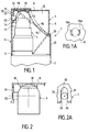
- a dispensing device 1 for, for example, diffusing a liquid product into fine droplets comprises a container 2, or bottle, containing the liquid to be diluted; the section of the container 2 can be of any shape, for example circular, or asymmetrical, and in particular of elliptical or elongated shape.
- the container 2 On its upper part, the container 2 is equipped with a distribution pump 4, in the example shown, carried by a cover 3 closing the container 2, as known per se.
- the pump 4 is actuated by a push button 5, the depression of which causes the sprayed liquid to exit through a nozzle 22 of horizontal axis, perpendicular to the longitudinal axis of the device 1, axis along which the 'depression.
- the device comprises a cover 6 suitable for covering the container 2 and the distribution pump 4, coming to fit over the contour of the cover 3.
- the cover 6 is equipped with an actuating member of the push button 5; this actuating member consists of a lever 7 generally having the shape of a right dihedral whose upper face 8 is horizontal when the container 2 is vertical, and a rear face 9 vertical; the upper face 8 is flat and is extended, at the front, by a vertical return 35 in which is formed a notch 20 crossed by the nozzle 22; the rear face 9, substantially cylindrical, fits in the outline inside the rear face 10 of the cover, itself similar to the rear face of the container 2.
- the faces 8 and 9 of the lever are laterally limited by walls, such as the wall 12 visible in FIG. 1, substantially tangent, internally, to the side walls of the cover 6.
- the walls 12 extend to the lower edge of the rear face 9, and stop at a certain distance behind the front edge 13 of the upper face 8; these side walls 12 are limited by an edge 15 in an arc.
- the cover 6 has, at its rear part, upwards, a notch limited by a contour 16 substantially in an arc, situated slightly above the edge 15 of the wings 12 of the lever 7 when the lever 7 is in the rest position. This indentation makes it possible to leave visible most of the lever 7 which completes the outline of the cover 6 at the right of this indentation.
- the lever 7 is articulated, at the lower end of the return 35 located at the front of the lever, on the front wall 17 of the cover 6, by a film hinge 14; the front wall 17 of the cover 6 also carries a notch 21 for the passage of the nozzle 22: the notch 21 and the notch 20 formed in the return 35 of the lever have an axial length sufficient to allow the nozzle 22 to s' discuss it, regardless of the vertical position of the push button 5.
- the lever 7 comprises, under its upper face 8, support means for exerting an action on the push button 5 these support means consist of a circular ring 18 centered on the axis of the push button 5 when the lever 7 is at rest; the upper part 19 of the push button 5 is a convex spherical surface, the annular lower end of the ring 18 defining a spherical bearing complementary to that of the upper part 19 of the push button 5; the diameter of the ring 18 is such that, when the lever 7 is in its maximum insertion position corresponding to the maximum insertion position of the push button 5, the ring 18 cooperates with the upper part 19 of the button pusher according to at least one zone located on the side of the film hinge 14 of the lever, in any case at most, along the axis of the push button 5; thanks to this arrangement, the combined action of the rotation of the lever 7 around the film hinge 14 and the downward movement of the push button 5 means that the result of the forces applied to the push button 5 remains substantially within the the axis of the pump 4, during the entire time
- the small overall height of the device according to the invention compared with those of the prior art: this is due, on the one hand, to the small axial dimensions of the ring 18 and, on the other hand , at the low position of the film hinge 14 at the lower end of the front wall 20 of the lever 7.
- the cover 6 comprises, at the rear, a means for hooking the rear part of the lever 7 to hold the lever 7 in the rest position; this attachment means consists of a spout 23 provided on the rear wall 10 of the cover 6, in the upper part, adapted to cooperate with a corresponding rim provided on the lower edge of the rear face 9 of the lever 7.
- FIG. 1A shows a variant of support means; according to this figure, the circular ring 18, described with reference to FIG. 1, is replaced by two circular segments 18A, 18B diametrically opposed.
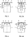
- Guide means are provided for positioning the cover-lever assembly relative to the nozzle 22 received in the notches 20 and 21, and guiding the lever 7 during its movement.
- these guide means are constituted by the edges 24 and 25 of the notch 20 provided on the front return 35 of the lever 7; the edges 24 and 25 are parallel to the longitudinal axis of the device and distant by a value equal to the diameter of the horizontal and cylindrical nozzle 22, of circular section.
- the anti-rotation guide means consist of a groove 27 provided in the vertical median plane in the push button 5; in the bleeding 27, takes place a stud 26 formed on the inner surface of the upper face 8 of the lever 7; the thickness of the stud 26 is equal to the width of the groove 27.
- the guide means consist of two flats 32, 33 provided on the spherical upper part of the push button 5; the two flats 32, 33 are parallel to the vertical median plane of the push button 5. These two flats 32, 33 cooperate respectively with two flat faces 30, 31 carried by vertical extensions 28, 29, diametrically opposite, of the ring 18 .
Landscapes
- Chemical & Material Sciences (AREA)
- Dispersion Chemistry (AREA)
- Engineering & Computer Science (AREA)
- Mechanical Engineering (AREA)
- Closures For Containers (AREA)
- Containers And Packaging Bodies Having A Special Means To Remove Contents (AREA)
- Devices For Dispensing Beverages (AREA)
Applications Claiming Priority (2)
| Application Number | Priority Date | Filing Date | Title |
|---|---|---|---|
| FR9207259A FR2692235B1 (fr) | 1992-06-16 | 1992-06-16 | Dispositif distributeur d'un produit liquide. |
| FR9207259 | 1992-06-16 |
Publications (2)
| Publication Number | Publication Date |
|---|---|
| EP0575213A1 true EP0575213A1 (de) | 1993-12-22 |
| EP0575213B1 EP0575213B1 (de) | 1995-07-26 |
Family
ID=9430779
Family Applications (1)
| Application Number | Title | Priority Date | Filing Date |
|---|---|---|---|
| EP93401381A Expired - Lifetime EP0575213B1 (de) | 1992-06-16 | 1993-06-01 | Ausgabevorrichtung für flüssige Produkte |
Country Status (6)
| Country | Link |
|---|---|
| US (1) | US5337927A (de) |
| EP (1) | EP0575213B1 (de) |
| JP (1) | JPH0672456A (de) |
| DE (1) | DE69300298T2 (de) |
| ES (1) | ES2074918T3 (de) |
| FR (1) | FR2692235B1 (de) |
Cited By (1)
| Publication number | Priority date | Publication date | Assignee | Title |
|---|---|---|---|---|
| US8881944B2 (en) | 2008-06-30 | 2014-11-11 | S.C. Johnson & Son, Inc. | Overcap for and a method of actuating a volatile material dispenser |
Families Citing this family (7)
| Publication number | Priority date | Publication date | Assignee | Title |
|---|---|---|---|---|
| US5992708A (en) * | 1997-07-15 | 1999-11-30 | Gaichuk; Andrew | Actuator nozzle |
| FR2768409B1 (fr) | 1997-09-17 | 1999-10-15 | Oreal | Ensemble de conditionnement et de distribution d'un produit liquide ou semi liquide |
| US6318595B1 (en) | 2000-06-08 | 2001-11-20 | Seaquistperfect Dispensing Foreign, Inc. | Finger-actuatable spray pump package with user-ready two-piece spray-through cap, pre-assembly cap, and method for making said package |
| US7651011B2 (en) * | 2001-04-16 | 2010-01-26 | Ben Z. Cohen | Microdispensing pump |
| US20080135581A1 (en) * | 2006-12-12 | 2008-06-12 | Timothy James Kennedy | Fluid Dispensing Systems for Pump Dispenser |
| USD717666S1 (en) | 2014-03-14 | 2014-11-18 | The Clorox Company | Fluid dispenser |
| FR3169735A1 (fr) | 2024-12-17 | 2026-06-19 | Aptar France Sas | Distributeur à poussoir pivotant |
Citations (6)
| Publication number | Priority date | Publication date | Assignee | Title |
|---|---|---|---|---|
| US2587040A (en) * | 1949-10-26 | 1952-02-26 | Edward H Green | Spray nozzle |
| US2685989A (en) * | 1950-06-16 | 1954-08-10 | Maryland Devices Inc | Pressure dispensing valve actuator |
| FR2367000A1 (fr) * | 1976-10-08 | 1978-05-05 | Intradal Produktie Bv | Capuchon perfectionne pour une bombe aerosol et bombe aerosol equipee d'un tel capuchon |
| FR2394467A1 (fr) * | 1977-06-15 | 1979-01-12 | Oreal | Dispositif de conditionnement et de distribution a levier de manoeuvre |
| GB1547072A (en) * | 1976-04-06 | 1979-06-06 | Yoshino Kogyosho Co Ltd | Cap for atomizer |
| EP0385077A2 (de) * | 1989-03-01 | 1990-09-05 | Coster - Tecnologie Speciali S.P.A. | Vorrichtung zum Zerstäuben einer kosmetischen, medizinischen, od. dgl. Flüssigkeit |
Family Cites Families (7)
| Publication number | Priority date | Publication date | Assignee | Title |
|---|---|---|---|---|
| CA702344A (en) * | 1965-01-19 | Revlon | Actuator for aerosol medication spray dispensers | |
| US3149761A (en) * | 1962-09-18 | 1964-09-22 | Johnson & Son Inc S C | Valve actuating assembly for pressurized containers |
| US3478938A (en) * | 1968-01-24 | 1969-11-18 | Ppg Industries Inc | Actuating device for pressurized containers |
| US4124148A (en) * | 1975-12-24 | 1978-11-07 | Firma Carl Vieler | Apparatus for a container with an atomizer for, in particular, cosmetic fluids |
| FR2398196A1 (fr) * | 1977-07-20 | 1979-02-16 | Aerosol Inventions Dev | Pompe a levier |
| US4186855A (en) * | 1978-06-19 | 1980-02-05 | Zotos International, Inc. | Spray pump actuating and bottle holding device |
| FR2675403B1 (fr) * | 1991-04-19 | 1993-08-13 | Oreal | Dispositif pour diffuser un produit liquide, notamment un produit capillaire, en fines gouttelettes. |
-
1992
- 1992-06-16 FR FR9207259A patent/FR2692235B1/fr not_active Expired - Fee Related
-
1993
- 1993-06-01 EP EP93401381A patent/EP0575213B1/de not_active Expired - Lifetime
- 1993-06-01 DE DE69300298T patent/DE69300298T2/de not_active Expired - Fee Related
- 1993-06-01 ES ES93401381T patent/ES2074918T3/es not_active Expired - Lifetime
- 1993-06-15 US US08/076,791 patent/US5337927A/en not_active Expired - Fee Related
- 1993-06-16 JP JP5145093A patent/JPH0672456A/ja active Pending
Patent Citations (6)
| Publication number | Priority date | Publication date | Assignee | Title |
|---|---|---|---|---|
| US2587040A (en) * | 1949-10-26 | 1952-02-26 | Edward H Green | Spray nozzle |
| US2685989A (en) * | 1950-06-16 | 1954-08-10 | Maryland Devices Inc | Pressure dispensing valve actuator |
| GB1547072A (en) * | 1976-04-06 | 1979-06-06 | Yoshino Kogyosho Co Ltd | Cap for atomizer |
| FR2367000A1 (fr) * | 1976-10-08 | 1978-05-05 | Intradal Produktie Bv | Capuchon perfectionne pour une bombe aerosol et bombe aerosol equipee d'un tel capuchon |
| FR2394467A1 (fr) * | 1977-06-15 | 1979-01-12 | Oreal | Dispositif de conditionnement et de distribution a levier de manoeuvre |
| EP0385077A2 (de) * | 1989-03-01 | 1990-09-05 | Coster - Tecnologie Speciali S.P.A. | Vorrichtung zum Zerstäuben einer kosmetischen, medizinischen, od. dgl. Flüssigkeit |
Cited By (1)
| Publication number | Priority date | Publication date | Assignee | Title |
|---|---|---|---|---|
| US8881944B2 (en) | 2008-06-30 | 2014-11-11 | S.C. Johnson & Son, Inc. | Overcap for and a method of actuating a volatile material dispenser |
Also Published As
| Publication number | Publication date |
|---|---|
| JPH0672456A (ja) | 1994-03-15 |
| DE69300298D1 (de) | 1995-08-31 |
| US5337927A (en) | 1994-08-16 |
| EP0575213B1 (de) | 1995-07-26 |
| FR2692235A1 (fr) | 1993-12-17 |
| ES2074918T3 (es) | 1995-09-16 |
| FR2692235B1 (fr) | 1996-05-15 |
| DE69300298T2 (de) | 1996-04-18 |
Similar Documents
| Publication | Publication Date | Title |
|---|---|---|
| EP0509872B1 (de) | Vorrichtung zur Diffusion eines flüssigen Produkts in feiner Tröpchenform | |
| EP1035038B1 (de) | Einheit zur Aufbewahrung und Ausgabe eines unter Druck stehenden Produktes, insbesondere von Kosmetika | |
| EP0626210B1 (de) | Verteilungseinrichtung einer bestimmten Dosis eines flüssigen oder pastösen Produktes | |
| EP0780324B1 (de) | Ausgabekop für ein plässiges oder viskoses produkt, sowie mit diesem versehener spender | |
| CH651270A5 (fr) | Capot de distribution pour recipient pressurise. | |
| EP0540129A1 (de) | Abgabevorrichtung für ein flüssiges Produkt, insbesondere kosmetischer oder pharmazeutischer Art | |
| FR2673608A1 (fr) | Distributeur de produit comprenant des moyens d'inviolabilite. | |
| EP0575213B1 (de) | Ausgabevorrichtung für flüssige Produkte | |
| EP0567374B1 (de) | Spenderkappe für flüssige oder pastöse Produkte | |
| FR2735188A1 (fr) | Dispositif a pompe pour prelever un liquide dans un recipient et le distribuer sous forme pulverisee | |
| EP0455552B1 (de) | Betätigungsvorrichtung für Ausgabeventil | |
| EP0271526B1 (de) | Kopf für die abgabe von halbflüssigem, teigigem oder zähflüssigem medium | |
| EP0605275B1 (de) | Anordnung zur Zerstäubung einer Flüssigkeit mit einer Vordruckpumpe | |
| EP0642990B1 (de) | Vorrichtung zur Ausgabe eines flüssigen Produktes | |
| EP0686576B1 (de) | Flüssigkeitsspender mit einem Abgabeventil und einem Druckknopf | |
| EP1162001A1 (de) | Reinigbarer Ausgabekopf und damit ausgerüsteter Ausgeber | |
| EP0818401A1 (de) | Sicherheitskappe und Ventilbetätiger für Aerosoldose | |
| FR2742138A1 (fr) | Distributeur de liquide | |
| FR2846639A1 (fr) | Dispositif de conditionnement et de distribution pour un produit liquide ou semi-liquide | |
| FR2814727A1 (fr) | Valve destinee a equiper un dispositif pour la distribution sous pression d'un produit, et dispositif ainsi equipe | |
| FR2517639A1 (fr) | Capot de distribution pour recipient pressurise et ensemble correspondant | |
| FR2659630A1 (fr) | Dispositif de conditionnement et de distribution d'un produit pulverisable. | |
| FR2591212A1 (fr) | Dispositif formant tire-bouchon, notamment pour une bouteille de vin petillant, tel que du champagne | |
| FR2723926A1 (fr) | Distributeur de produit liquide ou cremeux sous pression muni d'un bouton-poussoir equipe d'un systeme de non-violation | |
| FR2835812A1 (fr) | Dispositif de distribution protege contre un fonctionnement accidentel |
Legal Events
| Date | Code | Title | Description |
|---|---|---|---|
| PUAI | Public reference made under article 153(3) epc to a published international application that has entered the european phase |
Free format text: ORIGINAL CODE: 0009012 |
|
| 17P | Request for examination filed |
Effective date: 19930604 |
|
| AK | Designated contracting states |
Kind code of ref document: A1 Designated state(s): DE ES GB IT |
|
| 17Q | First examination report despatched |
Effective date: 19941007 |
|
| GRAA | (expected) grant |
Free format text: ORIGINAL CODE: 0009210 |
|
| AK | Designated contracting states |
Kind code of ref document: B1 Designated state(s): DE ES GB IT |
|
| ITF | It: translation for a ep patent filed | ||
| REF | Corresponds to: |
Ref document number: 69300298 Country of ref document: DE Date of ref document: 19950831 |
|
| GBT | Gb: translation of ep patent filed (gb section 77(6)(a)/1977) |
Effective date: 19950814 |
|
| REG | Reference to a national code |
Ref country code: ES Ref legal event code: FG2A Ref document number: 2074918 Country of ref document: ES Kind code of ref document: T3 |
|
| PLBE | No opposition filed within time limit |
Free format text: ORIGINAL CODE: 0009261 |
|
| STAA | Information on the status of an ep patent application or granted ep patent |
Free format text: STATUS: NO OPPOSITION FILED WITHIN TIME LIMIT |
|
| 26N | No opposition filed | ||
| REG | Reference to a national code |
Ref country code: GB Ref legal event code: IF02 |
|
| PGFP | Annual fee paid to national office [announced via postgrant information from national office to epo] |
Ref country code: GB Payment date: 20020529 Year of fee payment: 10 |
|
| PGFP | Annual fee paid to national office [announced via postgrant information from national office to epo] |
Ref country code: DE Payment date: 20020610 Year of fee payment: 10 |
|
| PGFP | Annual fee paid to national office [announced via postgrant information from national office to epo] |
Ref country code: ES Payment date: 20020618 Year of fee payment: 10 |
|
| PG25 | Lapsed in a contracting state [announced via postgrant information from national office to epo] |
Ref country code: GB Free format text: LAPSE BECAUSE OF NON-PAYMENT OF DUE FEES Effective date: 20030601 |
|
| PG25 | Lapsed in a contracting state [announced via postgrant information from national office to epo] |
Ref country code: ES Free format text: LAPSE BECAUSE OF NON-PAYMENT OF DUE FEES Effective date: 20030602 |
|
| PG25 | Lapsed in a contracting state [announced via postgrant information from national office to epo] |
Ref country code: DE Free format text: LAPSE BECAUSE OF NON-PAYMENT OF DUE FEES Effective date: 20040101 |
|
| GBPC | Gb: european patent ceased through non-payment of renewal fee |
Effective date: 20030601 |
|
| REG | Reference to a national code |
Ref country code: ES Ref legal event code: FD2A Effective date: 20030602 |
|
| PG25 | Lapsed in a contracting state [announced via postgrant information from national office to epo] |
Ref country code: IT Free format text: LAPSE BECAUSE OF NON-PAYMENT OF DUE FEES;WARNING: LAPSES OF ITALIAN PATENTS WITH EFFECTIVE DATE BEFORE 2007 MAY HAVE OCCURRED AT ANY TIME BEFORE 2007. THE CORRECT EFFECTIVE DATE MAY BE DIFFERENT FROM THE ONE RECORDED. Effective date: 20050601 |