EP0575263A1 - Rinne für elektrische Stromversorgungsvorrichtung - Google Patents
Rinne für elektrische Stromversorgungsvorrichtung Download PDFInfo
- Publication number
- EP0575263A1 EP0575263A1 EP93420233A EP93420233A EP0575263A1 EP 0575263 A1 EP0575263 A1 EP 0575263A1 EP 93420233 A EP93420233 A EP 93420233A EP 93420233 A EP93420233 A EP 93420233A EP 0575263 A1 EP0575263 A1 EP 0575263A1
- Authority
- EP
- European Patent Office
- Prior art keywords
- wall
- chute
- cables
- profile
- profiles
- Prior art date
- Legal status (The legal status is an assumption and is not a legal conclusion. Google has not performed a legal analysis and makes no representation as to the accuracy of the status listed.)
- Granted
Links
- 230000000717 retained effect Effects 0.000 claims 1
- 238000009434 installation Methods 0.000 description 6
- 238000010616 electrical installation Methods 0.000 description 2
- 238000003754 machining Methods 0.000 description 2
- 239000011324 bead Substances 0.000 description 1
- 238000000465 moulding Methods 0.000 description 1
- 230000003287 optical effect Effects 0.000 description 1
Images


Classifications
-
- H—ELECTRICITY
- H02—GENERATION; CONVERSION OR DISTRIBUTION OF ELECTRIC POWER
- H02G—INSTALLATION OF ELECTRIC CABLES OR LINES, OR OF COMBINED OPTICAL AND ELECTRIC CABLES OR LINES
- H02G3/00—Installations of electric cables or lines or protective tubing therefor in or on buildings, equivalent structures or vehicles
- H02G3/02—Details
- H02G3/04—Protective tubing or conduits, e.g. cable ladders or cable troughs
- H02G3/0431—Wall trunking
Definitions
- the present invention relates generally to a chute for an electrical distribution device.
- An electrical distribution device is generally constituted by a horizontal, elongated and constant section trough, intended to support or guide electric cables, and by at least one box intended to be fixed laterally along the trough.
- Another drawback is that it is generally necessary to modify the cover of the chute when it is desired to modify the position of an apparatus along this chute.
- trunking have dimensions in their cross section which are fixed for a given trunking model, and it is therefore necessary for an installer to have several different trunking models to be able to carry out an electrical installation.
- optimized electrical distribution that is to say in which the different troughs are not substantially oversized with respect to the number of cables contained in each of these troughs.
- Another drawback is that it is generally necessary for the installer to carry out a resumption of machining or a similar operation in order to produce openings or lights allowing the cables to be passed which must be connected to equipment.
- An object of the present invention is to provide a trunking for a distributed electrical distribution device making it possible to install cables more conveniently in the trunking and making it possible to subsequently increase the capacity for installing cables in the trunking.
- Another object of the present invention to provide such a chute allowing the addition of a cable in an existing installation without requiring disassembly or bypassing of the equipment installed along the chute.
- Another object of the present invention consists in proposing such a chute in which the cover of the chute must not be modified at the level of the zone of the chute which supports an apparatus.
- Another object of the present invention consists in proposing such a trunking which can be economically constituted by a relatively small number of different parts, these parts however making it possible to compose several heights and / or several different widths of trunking.
- Another object of the present invention is to provide such a chute not requiring resumption of machining to produce lights for passing the cables which must be connected to equipment.
- Another object of the present invention to provide such a chute for installing along it apparatus without any constraint step.
- the invention therefore relates to a chute for a distributed electrical distribution device.
- the chute comprises a plurality of consoles intended to be fixed to a wall of a room in a substantially aligned and spaced from each other, an upper profile and a lower profile which is parallel to the upper profile. and spaced therefrom so as to form between the two profiles a continuous light;
- the upper section comprises a first substantially vertical wall for fixing against said consoles and a second wall projecting forward by forming a path for supporting the first cables;
- the lower section comprises a third substantially vertical wall for fixing against said consoles and a fourth wall projecting forward by forming a path for supporting second cables; and a part of any one of said first and second cables which is intended to be connected to an apparatus located laterally along the trough extends laterally from said path, laterally crosses said light and opens out at the rear of the trough to be connected to said apparatus.
- said upper section further comprises a fifth wall which is substantially horizontal, upper and projecting towards the front, having a width substantially equal to that of said fourth wall, and in that it is provided a substantially planar and vertical cover, the upper edge of which is detachably connected to the front edge of said fifth wall and the lower edge of which is detachably connected to the front edge of said fourth wall.
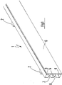
- FIG 1 there is generally a assembled chute which is arranged horizontally against a vertical wall (not shown) of a room.
- the chute 1 essentially comprises a plurality of consoles 2 intended to be fixed to a wall of a room (for example a vertical wall), an upper profile 3 and a lower profile 4.
- the consoles 2 are fixed to the wall in a substantially aligned and evenly spaced.
- the chute further comprises an intermediate section 5 and a side cover 6.
- the sections 3, 4, 5 and the side cover 6 are all elongated parts which have a substantially constant cross section on all their length.
- the three sections 3, 4 and 5 are arranged one above the other, in a parallel manner and are spaced from one another so as to form between them two parallel slots 7, 8 extending longitudinally.
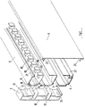
- FIG 2 we distinguish in more detail each of the elements that together constitute the chute.
- a single console 2 which has a substantially vertical rear wall 10 which is intended to be applied against the wall of the room (for example a wall) on which it is desired to fix the chute. From this rear wall 10, three fastening means 11, 12, 13 are projected forward. Each of these fastening means is intended to receive laterally one of the three sections 3, 4 or 5 so that this section can be fixed removably or dismountably on this fixing means 11, 12 or 13.
- the profile 3 has at its rear face 14 elements fixing 15, 16 which snap in or detachably fix, by a simple pressure, on other fixing elements 17, 18 formed on the front face of the fixing means 11 of the console 2.
- the element 17 can be constituted by a longitudinal cylindrical bead and the corresponding element 15 can be constituted by a longitudinal cylindrical recess comprising a longitudinal lateral opening, so that it can be fitted by pressing on the element 17.
- the element 18 can be constituted by a longitudinal bevelled edge whose cross-sectional shape is that of a sawtooth hook and the element 16 may have the shape of a longitudinal edge.
- the mounting of the profile 3 on the fixing means 11 can be carried out as follows. We start by fitting the element 15 onto the element 17 then we rotate the element 3 slightly around these nested elements 15 and 17 which together form a joint of small clearance, until the flange 16 comes to slide on the bevelled face of the element 18 in order to engage or snap onto this element 18. To then separate the profile 3 from the fixing means 11 of the console 2, it suffices to exert a tensile force on the element 3 so as to dislodge the rim 16 of the element 18 and then to disengage the element 15 from the element 17. It is seen that all of these elements 15, 16, 17, 18 can have a shape in constant cross section over the length respectively of the profile 3 and the console 2. These fastening elements are therefore very easy to produce by molding.
- Similar fixing elements are also provided at the level of the section 4 and the fixing means 13, these elements being arranged symmetrically with respect to a horizontal plane. These elements will therefore not described in more detail. Similar assembly elements can also be provided on the intermediate section 5 and on the fixing means 12 which corresponds to it. However, in the exemplary embodiment, these fixing elements of the profile 5 and the fixing means 12 are provided in a similar manner to the elements 16 and 18 which are provided on the profile 3 and the corresponding fixing means 11.
- fixing means and fixing elements of various shapes, as is well known in the prior art.
- the only criterion to be observed here is that of a removable or dismountable fixing function, preferably a fixing by push-fit, that is to say a fixing without separate fixing member.
- the front cover 6 is in the general form of a substantially vertical wall. At a front upper edge of the profile 3, a removable fixing element 21 is formed and at a lower front edge of the lower profile 4 is formed another removable fixing element 22.
- a removable fixing element 23 is provided at the upper edge of the cover 6 and the element 23 cooperates with the element 21 to provide removable fixing by snap-fastening or by pressing the cover 6 with the profile 3 and, in a similar manner, a fixing element removable 24 is provided at the lower edge of the cover 6 and the element 24 comes to cooperate with the element 22 to ensure a removable fixing by snap-fastening or by pressure of the cover 6 with the profile 4.
- the upper profile 3 essentially comprises a first substantially vertical wall 30 making it possible to support the fastening elements 15, 16 in order to removably fix the profile 3 on the console 2.
- the profile 3 also comprises a second wall 31 which is substantially horizontal, lower and projecting forward from the first wall 30, in order to constitute a path for supporting the first cables 32.
- the lower profile 4 comprises a third wall 33 substantially vertical for its attachment to the console 2 and a fourth wall 34 substantially horizontal, lower and projecting forward from the third wall 33 in order to constitute a path for supporting second cables 35.
- the intermediate profile 5 comprises a fifth wall 36 substantially vertical for its attachment to the console 2 and a sixth wall 37 substantially horizontal, lower and projecting forward from the fifth pa king 36 in order to constitute a path to support third cables 38.
- the second wall 31, the fourth wall 34 and the sixth wall 37 each have, at its front edge, an upwardly directed rim 39, 40, 41 which makes it possible to retain the cables 32, 35 forwards. 38 so that these are relatively guided laterally to extend longitudinally in the chute.
- the upper profile 3 comprises at in addition to an eighth wall 43 substantially horizontal, upper and extending forward from the first wall 30. If the width A of the substantially horizontal wall 31 is substantially equal to the width A of the substantially horizontal upper wall 43, when the cover 6 is mounted laterally, coming to be fixed at the level of the front edge 23 of the upper wall 43, the internal face 44 of the cover 6 comes into contact with or comes close to the front end 39 of the lower wall 31. 11 results from this that the upper profile 3 defines, when the cover 6 is mounted, an internal volume which is substantially closed in which the cables 32 can extend.
- the second wall 31 of the profile 3 comprises a plurality of notches 45 open at its front edge 39 in order to allow it to pass through (arrow F1) of any one of these notches 45, from top to bottom, a part 32E of any one of said first cables 32 which is intended to be connected to an apparatus (not shown) situated laterally near the chute.
- the arrow F1 indicates the path that such an end of cable 32E can follow when it comes from one of the cables 32. It can be seen that the end of cable 32E passes downwards through the wall 31 passing through a notch 45, then passes through the lumen 7 and finally emerges at the rear of the chute.
- a part 32E which opens at the rear of the chute 1 in order to be connected to an electrical apparatus (not shown) located laterally near the chute.
- One end of one of the cables 35 can pass directly, from above through the light 7, as shown by the arrow F2.
- one end of one of the cables 38 can pass directly, from above through the light 8, as shown by the arrow F3.
- said part 32E of any one of said first cables 32 or 32A, second cables 35 and third cables 38 which is intended to be connected to an appliance crosses the closest of the two lights 7 or 8.
- the brackets 2 are also provided with holes 47, 48 for the passage of screws for fixing the brackets to a wall 50 of the room. These holes are arranged at the level of the opening (s) 7, 8 so that the screws (not shown) can be directly accessed by passing a tool through the opening (s) 7, 8.
- FIG. 5 there is a variant in which the second wall 31A of the section 3A has a width B less than that A of the said fifth wall 43A of the section 3A, so as to leave a space 46 between the front edge 39A of the second wall 31A and the internal face 44 of the cover 6, in order to allow passage through this space 46, from top to bottom (arrow F4), the part 32E of any of the first cables 32A which is intended to be connected to an apparatus (not shown) located laterally near the chute.
- the chute for an electrical distribution device makes it possible to install cables more conveniently in the chute, because the entire front of the chute is released when the cover 6 is removed, and allows subsequent installation of additional cables in the chute. It is indeed possible to add a cable to an existing installation without requiring disassembly or bypassing of the devices installed along the chute, because the devices are not arranged at the front of the chute but are arranged above or below the chute. These devices therefore do not hinder access to the interior of the chute since this interior of the chute is completely released laterally when the cover 6 is removed.
- the part 32E of the cables can open laterally from the chute, passing through one of the openings 7 or 8 which are longitudinal and continuous, without constraint of step, that is to say that the part 32E can open n ' anywhere along the chute and not in specific places spaced a certain step.
- the chute consists of the set of profiles and brackets which makes it possible to form at least one continuous light in an easy, economical and modular manner.
- cover 6 of the chute must not be modified at the level of the zone of the chute which supports an apparatus.
- such a chute can be produced economically by using a relatively small number of different parts.
- an installer can optimally arrange a distributed electrical distribution installation and can then easily modify this installation.
Landscapes
- Engineering & Computer Science (AREA)
- Architecture (AREA)
- Civil Engineering (AREA)
- Structural Engineering (AREA)
- Chutes (AREA)
- Details Of Indoor Wiring (AREA)
Applications Claiming Priority (2)
| Application Number | Priority Date | Filing Date | Title |
|---|---|---|---|
| FR9207323A FR2692412B1 (fr) | 1992-06-15 | 1992-06-15 | Goulotte pour dispositif de distribution électrique. |
| FR9207323 | 1992-06-15 |
Publications (2)
| Publication Number | Publication Date |
|---|---|
| EP0575263A1 true EP0575263A1 (de) | 1993-12-22 |
| EP0575263B1 EP0575263B1 (de) | 1996-11-27 |
Family
ID=9430823
Family Applications (1)
| Application Number | Title | Priority Date | Filing Date |
|---|---|---|---|
| EP19930420233 Expired - Lifetime EP0575263B1 (de) | 1992-06-15 | 1993-06-09 | Rinne für elektrische Stromversorgungsvorrichtung |
Country Status (4)
| Country | Link |
|---|---|
| EP (1) | EP0575263B1 (de) |
| DE (1) | DE69306175D1 (de) |
| ES (1) | ES2095614T3 (de) |
| FR (1) | FR2692412B1 (de) |
Cited By (2)
| Publication number | Priority date | Publication date | Assignee | Title |
|---|---|---|---|---|
| AT4580U3 (de) * | 1999-04-06 | 2002-02-25 | Eurotray Stapelbehaelter | Kanal für die aufnahme von leitungen |
| EP1187286A3 (de) * | 2000-08-31 | 2004-01-07 | HAGER ELECTRO GmbH | Kabelhalter für Stromverteiler |
Families Citing this family (2)
| Publication number | Priority date | Publication date | Assignee | Title |
|---|---|---|---|---|
| FR2979758B1 (fr) * | 2011-09-06 | 2014-05-09 | Schneider Electric Ind Sas | Dispositif de rangement des conducteurs de cablage des appareillages dans une armoire electrique equipee de rails de montage desdits appareillages |
| CN219144784U (zh) * | 2022-09-14 | 2023-06-06 | 阳光储能技术有限公司 | 储能设备的柜体总成及具有其的储能设备 |
Citations (2)
| Publication number | Priority date | Publication date | Assignee | Title |
|---|---|---|---|---|
| DE2431834A1 (de) * | 1974-07-02 | 1976-01-22 | Josef Rocek | Leitungsfuehrung fuer auf wandflaechen zu verlegende kabel oder dgl. |
| EP0271891A2 (de) * | 1986-12-17 | 1988-06-22 | Johann Paul Schifferle | Kabelführungskanal zur Aufnahme von Starkstrom- und Fernmeldekabel |
-
1992
- 1992-06-15 FR FR9207323A patent/FR2692412B1/fr not_active Expired - Fee Related
-
1993
- 1993-06-09 ES ES93420233T patent/ES2095614T3/es not_active Expired - Lifetime
- 1993-06-09 DE DE69306175T patent/DE69306175D1/de not_active Expired - Lifetime
- 1993-06-09 EP EP19930420233 patent/EP0575263B1/de not_active Expired - Lifetime
Patent Citations (2)
| Publication number | Priority date | Publication date | Assignee | Title |
|---|---|---|---|---|
| DE2431834A1 (de) * | 1974-07-02 | 1976-01-22 | Josef Rocek | Leitungsfuehrung fuer auf wandflaechen zu verlegende kabel oder dgl. |
| EP0271891A2 (de) * | 1986-12-17 | 1988-06-22 | Johann Paul Schifferle | Kabelführungskanal zur Aufnahme von Starkstrom- und Fernmeldekabel |
Cited By (2)
| Publication number | Priority date | Publication date | Assignee | Title |
|---|---|---|---|---|
| AT4580U3 (de) * | 1999-04-06 | 2002-02-25 | Eurotray Stapelbehaelter | Kanal für die aufnahme von leitungen |
| EP1187286A3 (de) * | 2000-08-31 | 2004-01-07 | HAGER ELECTRO GmbH | Kabelhalter für Stromverteiler |
Also Published As
| Publication number | Publication date |
|---|---|
| DE69306175D1 (de) | 1997-01-09 |
| FR2692412A1 (fr) | 1993-12-17 |
| ES2095614T3 (es) | 1997-02-16 |
| EP0575263B1 (de) | 1996-11-27 |
| FR2692412B1 (fr) | 1994-09-02 |
Similar Documents
| Publication | Publication Date | Title |
|---|---|---|
| EP1276197B1 (de) | Zusatz für Kabelrinnen mit Abschnitten unterschiedlicher Höhe | |
| EP1056177A1 (de) | Vorläufige Verteilungsstation | |
| EP0575263B1 (de) | Rinne für elektrische Stromversorgungsvorrichtung | |
| EP0813663B1 (de) | Eckverbindungsvorrichtung für eine rinnenförmige leitung und eine abdeckung wie z.b. eine profilleiste, eine sockelleiste oder eine rinne, insbesondere für ein elektrisches bauteil | |
| FR2814293A1 (fr) | Dispositif pour l'implantation encastree d'au moins un appareillage electrique dans un conduit de cablage de profondeur inferieure a celle de l'appareillage | |
| EP0921546A1 (de) | Durchführungsvorrichtung, insbesondere für Gehäuse für elektrische Geräte | |
| EP1164675B1 (de) | Abzweigungszubehör zur Positionierung zwischen zwei Kabelrinnen | |
| CH690532A5 (fr) | Gaine d'allège. | |
| EP0267079B1 (de) | Abzweigungszubehör für Verkabelungsrohr | |
| EP0573367B1 (de) | Kanal für elektrische Anlage | |
| EP0481878A1 (de) | Installationskanal für Arbeitsplatte(n) zur Zuführung von Kabeln zu Einrichtungen auf den Arbeitsplatte(n) | |
| FR2759561A1 (fr) | Etagere comportant au moins un montant vertical et des plateaux d'etagere | |
| FR2615052A1 (fr) | Enrouleur, en particulier pour cable electrique | |
| FR2690599A1 (fr) | Boîtier isolant de connexion électrique, montable notamment dans un poteau évidé tel qu'un support de lampadaire. | |
| EP2113977B1 (de) | Montagezubehör für ein Elektrogerät in einem Kabelkanal und elektrische Baugruppe bestehend aus einem Elektrogerät und solch einem Montagezubehör | |
| EP0028553B1 (de) | Niederspannungsverteilerkasten mit Erhöhungssockel | |
| BE1003141A6 (fr) | Boite sous plancher. | |
| FR2810467A1 (fr) | Dispositif de montage d'un appareil electrique sur un conduit de cablage | |
| EP1211773B1 (de) | Träger für ein Gerät, inbesondere für ein elektrisches Gerät, zur Befestigung auf einem Kabelkanalkörper | |
| EP0473482B1 (de) | Befestigungsgehäuse für elektrisches Gerät | |
| FR2669175A1 (fr) | Boitier ouvrant et modulable pour appareillage(s) electrique(s). | |
| FR2817719A1 (fr) | Colonne bureautique | |
| EP0848470B1 (de) | Kanal für elektrische Anlage und Verwendung | |
| FR2730869A1 (fr) | Equipement modulaire pour la fixation, le cablage et la protection d'appareillages electriques | |
| EP1587197B1 (de) | Einbaudose mit Verbindungszubehör für einen Kanal |
Legal Events
| Date | Code | Title | Description |
|---|---|---|---|
| PUAI | Public reference made under article 153(3) epc to a published international application that has entered the european phase |
Free format text: ORIGINAL CODE: 0009012 |
|
| AK | Designated contracting states |
Kind code of ref document: A1 Designated state(s): BE CH DE ES GB IT LI SE |
|
| 17P | Request for examination filed |
Effective date: 19940520 |
|
| RAP1 | Party data changed (applicant data changed or rights of an application transferred) |
Owner name: SCHNEIDER ELECTRIC SA |
|
| 17Q | First examination report despatched |
Effective date: 19950728 |
|
| GRAG | Despatch of communication of intention to grant |
Free format text: ORIGINAL CODE: EPIDOS AGRA |
|
| GRAH | Despatch of communication of intention to grant a patent |
Free format text: ORIGINAL CODE: EPIDOS IGRA |
|
| GRAH | Despatch of communication of intention to grant a patent |
Free format text: ORIGINAL CODE: EPIDOS IGRA |
|
| GRAA | (expected) grant |
Free format text: ORIGINAL CODE: 0009210 |
|
| AK | Designated contracting states |
Kind code of ref document: B1 Designated state(s): BE CH DE ES GB IT LI SE |
|
| PG25 | Lapsed in a contracting state [announced via postgrant information from national office to epo] |
Ref country code: GB Effective date: 19961127 |
|
| REF | Corresponds to: |
Ref document number: 69306175 Country of ref document: DE Date of ref document: 19970109 |
|
| REG | Reference to a national code |
Ref country code: ES Ref legal event code: FG2A Ref document number: 2095614 Country of ref document: ES Kind code of ref document: T3 |
|
| ITF | It: translation for a ep patent filed | ||
| PG25 | Lapsed in a contracting state [announced via postgrant information from national office to epo] |
Ref country code: SE Effective date: 19970227 |
|
| PG25 | Lapsed in a contracting state [announced via postgrant information from national office to epo] |
Ref country code: DE Effective date: 19970228 |
|
| GBV | Gb: ep patent (uk) treated as always having been void in accordance with gb section 77(7)/1977 [no translation filed] |
Effective date: 19961127 |
|
| PLBE | No opposition filed within time limit |
Free format text: ORIGINAL CODE: 0009261 |
|
| STAA | Information on the status of an ep patent application or granted ep patent |
Free format text: STATUS: NO OPPOSITION FILED WITHIN TIME LIMIT |
|
| 26N | No opposition filed | ||
| PGFP | Annual fee paid to national office [announced via postgrant information from national office to epo] |
Ref country code: CH Payment date: 19990614 Year of fee payment: 7 |
|
| PGFP | Annual fee paid to national office [announced via postgrant information from national office to epo] |
Ref country code: BE Payment date: 19990819 Year of fee payment: 7 |
|
| PG25 | Lapsed in a contracting state [announced via postgrant information from national office to epo] |
Ref country code: LI Free format text: LAPSE BECAUSE OF NON-PAYMENT OF DUE FEES Effective date: 20000630 Ref country code: CH Free format text: LAPSE BECAUSE OF NON-PAYMENT OF DUE FEES Effective date: 20000630 Ref country code: BE Free format text: LAPSE BECAUSE OF NON-PAYMENT OF DUE FEES Effective date: 20000630 |
|
| BERE | Be: lapsed |
Owner name: S.A. SCHNEIDER ELECTRIC Effective date: 20000630 |
|
| REG | Reference to a national code |
Ref country code: CH Ref legal event code: PL |
|
| PGFP | Annual fee paid to national office [announced via postgrant information from national office to epo] |
Ref country code: ES Payment date: 20020618 Year of fee payment: 10 |
|
| PG25 | Lapsed in a contracting state [announced via postgrant information from national office to epo] |
Ref country code: ES Free format text: LAPSE BECAUSE OF NON-PAYMENT OF DUE FEES Effective date: 20030610 |
|
| REG | Reference to a national code |
Ref country code: ES Ref legal event code: FD2A Effective date: 20030610 |
|
| PG25 | Lapsed in a contracting state [announced via postgrant information from national office to epo] |
Ref country code: IT Free format text: LAPSE BECAUSE OF NON-PAYMENT OF DUE FEES;WARNING: LAPSES OF ITALIAN PATENTS WITH EFFECTIVE DATE BEFORE 2007 MAY HAVE OCCURRED AT ANY TIME BEFORE 2007. THE CORRECT EFFECTIVE DATE MAY BE DIFFERENT FROM THE ONE RECORDED. Effective date: 20050609 |