EP0575285A1 - Heat exchanger for heat recovering ventilation - Google Patents
Heat exchanger for heat recovering ventilation Download PDFInfo
- Publication number
- EP0575285A1 EP0575285A1 EP93610035A EP93610035A EP0575285A1 EP 0575285 A1 EP0575285 A1 EP 0575285A1 EP 93610035 A EP93610035 A EP 93610035A EP 93610035 A EP93610035 A EP 93610035A EP 0575285 A1 EP0575285 A1 EP 0575285A1
- Authority
- EP
- European Patent Office
- Prior art keywords
- heat exchanger
- fluid
- box device
- heat
- opening
- Prior art date
- Legal status (The legal status is an assumption and is not a legal conclusion. Google has not performed a legal analysis and makes no representation as to the accuracy of the status listed.)
- Withdrawn
Links
- 238000009423 ventilation Methods 0.000 title description 4
- 239000012530 fluid Substances 0.000 claims abstract description 115
- 230000005540 biological transmission Effects 0.000 claims abstract description 7
- QGZKDVFQNNGYKY-UHFFFAOYSA-N Ammonia Chemical compound N QGZKDVFQNNGYKY-UHFFFAOYSA-N 0.000 description 6
- 241001465754 Metazoa Species 0.000 description 6
- 239000000428 dust Substances 0.000 description 6
- 230000000087 stabilizing effect Effects 0.000 description 5
- 229910021529 ammonia Inorganic materials 0.000 description 3
- 238000010276 construction Methods 0.000 description 3
- 239000002245 particle Substances 0.000 description 3
- 238000000926 separation method Methods 0.000 description 3
- 230000000903 blocking effect Effects 0.000 description 1
- 230000005494 condensation Effects 0.000 description 1
- 238000009833 condensation Methods 0.000 description 1
- 230000001419 dependent effect Effects 0.000 description 1
- 210000003608 fece Anatomy 0.000 description 1
- 238000009434 installation Methods 0.000 description 1
- 239000007788 liquid Substances 0.000 description 1
- 239000010871 livestock manure Substances 0.000 description 1
- 238000004519 manufacturing process Methods 0.000 description 1
- 239000000463 material Substances 0.000 description 1
- 239000000203 mixture Substances 0.000 description 1
- 230000002265 prevention Effects 0.000 description 1
- 230000000717 retained effect Effects 0.000 description 1
- 230000035939 shock Effects 0.000 description 1
Images


Classifications
-
- F—MECHANICAL ENGINEERING; LIGHTING; HEATING; WEAPONS; BLASTING
- F24—HEATING; RANGES; VENTILATING
- F24F—AIR-CONDITIONING; AIR-HUMIDIFICATION; VENTILATION; USE OF AIR CURRENTS FOR SCREENING
- F24F12/00—Use of energy recovery systems in air conditioning, ventilation or screening
- F24F12/001—Use of energy recovery systems in air conditioning, ventilation or screening with heat-exchange between supplied and exhausted air
- F24F12/006—Use of energy recovery systems in air conditioning, ventilation or screening with heat-exchange between supplied and exhausted air using an air-to-air heat exchanger
-
- F—MECHANICAL ENGINEERING; LIGHTING; HEATING; WEAPONS; BLASTING
- F24—HEATING; RANGES; VENTILATING
- F24F—AIR-CONDITIONING; AIR-HUMIDIFICATION; VENTILATION; USE OF AIR CURRENTS FOR SCREENING
- F24F7/00—Ventilation
- F24F7/04—Ventilation with ducting systems, e.g. by double walls; with natural circulation
- F24F7/06—Ventilation with ducting systems, e.g. by double walls; with natural circulation with forced air circulation, e.g. by fan positioning of a ventilator in or against a conduit
- F24F7/08—Ventilation with ducting systems, e.g. by double walls; with natural circulation with forced air circulation, e.g. by fan positioning of a ventilator in or against a conduit with separate ducts for supplied and exhausted air with provisions for reversal of the input and output systems
-
- Y—GENERAL TAGGING OF NEW TECHNOLOGICAL DEVELOPMENTS; GENERAL TAGGING OF CROSS-SECTIONAL TECHNOLOGIES SPANNING OVER SEVERAL SECTIONS OF THE IPC; TECHNICAL SUBJECTS COVERED BY FORMER USPC CROSS-REFERENCE ART COLLECTIONS [XRACs] AND DIGESTS
- Y02—TECHNOLOGIES OR APPLICATIONS FOR MITIGATION OR ADAPTATION AGAINST CLIMATE CHANGE
- Y02B—CLIMATE CHANGE MITIGATION TECHNOLOGIES RELATED TO BUILDINGS, e.g. HOUSING, HOUSE APPLIANCES OR RELATED END-USER APPLICATIONS
- Y02B30/00—Energy efficient heating, ventilation or air conditioning [HVAC]
- Y02B30/56—Heat recovery units
Definitions
- the present invention relates to a heat exchanger arrangement for the recuperation of heat, in particular for recuperation of heat from a fluid, such as a gaseous fluid and transmission of this heat to another, colder fluid, such as a gaseous fluid, whereby the heat exchanger arrangement is of a kind there the two fluids pass through a heat exchanger in opposite directions.
- a large number of heat exchangers of this type are known, comprising those where the two fluids are carried to and from the heat exchanger in a coaxial relationship to each other.
- the two fluids to, respectively from the heat exchanger may be connected to in particular the ceiling and floor areas of a stable space by means of simple straight pipes.
- the heat exchanger arrangement comprise a heat exchanger which is provided with an input at one heat exchanger end for one of the fluids and with an output for the same fluid at the opposite end whereby there is provided for the fluid at least either an input box device and/or an output box device in conjunction with the heat exchanger, and where the heat exchanger by means of a side close to that end which is provided with an output is provided with an input for the other fluid and that the heat exchanger at a side close to the the other end provided with an input is provided with an output for the other fluid, which fluid is conducted via a box device disposed along this side of the heat exchanger to a place, section or area of consumption for heat exchanged fluid.
- a heat exchanger arrangement which is easily fitted with one or two register arrangements by means of which such a desired control of the ventilation air in particular in stables for young or recently born animals may be obtained in a fairly simple manner.
- a heat exchanger arrangement according to the invention may be designed and installed in a way such that the heat exchanger with the box elements mentioned may be fitted to the outside of a wall with two fluid conduits one above the other with a distance between them and leading through the wall in order that the fluid that flows into in particular the stable space into the ceiling area through the uppermost conduit, while the other fluid, the heat of which it is desired to recuperate, is led out through the lowermost conduit which will normally be fitted somewhat above floor level.
- This solution may be advantageous in stables with e.g. slatted floor because inavoidable condensate generated in the the heat exchanger may flow directly through the latticed floor and further to a liquid manure collecting arrangement.
- the fluid which flows from this area in the stable contains fairly large amounts of ammonia as well as a considerable part of dust or dust particles, and neither the ammonia, nor the dust or the the dust particles are desired back into the stable again. This is to be obtained as efficiently as possible by means of the embodiments according to the invention.
- heat exchanger arrangements are characterized in that the last mentioned box device disposed along the side of the heat exchanger is fitted with at least one further opening facing away from the heat exchanger and that a register arrangement is fitted which simultaneously opens, respectively closes this opening and the path for fluid through the box device from the heat exchanger to the discharge opening for this fluid of the heat exchanger arrangement.
- the fluid which flows into the stable may comprise a suitable given and controllable proportion between fluid heated by heat recuperation and fluid which has a temperature which corresponds to the temperature of the fluid before passage through the heat recuperating heat exchanger according to the invention.
- a further development according to the invention for its improvement is characterized in that a box device is fitted which connects the areas of the first mentioned two box devices along the the first mentioned of the sides of the heat exchanger, the box device being fitted with a passage register which adjusts the amount of fluid which passes through this box device and bypasses the input flow into the heat exchanger for the second of the two fluids.
- the heat recuperation efficiency may be adjusted from a suitably low efficiency determined by the mechanical proportion of the cross sections determined by the proportion between on the one hand the heat axchanger cross section for the first fluid and on the other hand the sum of this heat exchanger cross section plus the cross section of the conduit with the fully open passage register, to the maximum heat recuperation efficiency obtainable.
- An embodiment which is advantageous both for the heat exchanger arrangement and for the installation of the heat exchanger is according to the invention characteristic in that the heat exchanger is fitted in particular to the outside of the wall of a building, in that the box device with the said register arrangement is disposed closest to this wall and preferably parallel to it and with the said opening for passage of fluid disposed at a distance from the wall which corresponds to the cross section of the fluid flow.
- the box device with the said register arrangement is disposed closest to this wall and preferably parallel to it and with the said opening for passage of fluid disposed at a distance from the wall which corresponds to the cross section of the fluid flow.
- An embodiment which ensures a high heat recuperation is according to the invention in particular obtained if the heat exchanger is disposed with a mainly rectangular cross section and with the longest side of the rectangle of the cross section disposed closest to the two box devices disposed along the sides of the heat exchanger.
- the heat exchanger is hereby placed rather centrally in the combined heat exchanger arrangement and in such a way that as an ensemble a high heat exchanger surface area is obtained between the two media flows and small heat losses to the surroundings.
- box device which is the last mentioned according to the first solution mentioned above and which is the box device that is disposed along the side of the heat exchanger (VV) is provided with at least one further opening directed away from the heat exchanger for passage of fluid from the heat exchanger through the box device and along to a further box device and to the discharge opening for this fluid of the heat exchanger arrangement, which further box device may at the same time be common to at least one further heat recuperating heat exchanger.
- the invention is characterized in that the said input opening for the second fluid is connected to the further box device which comprises at least one opening in a wall which serves as the said input opening for this fluid and that in the further box device is disposed a separating register element or a separating wall between fluid arriving at the input of the heat exchanger and fluid flowing to the discharge.
- the heat exchanger is characteristic in that the last mentioned register element in its function as a shunt register element between the arriving and the discharged parts of the last mentioned fluid completely or partly takes over the function of the register arrangement disposed in the first mentioned box device.
- a register arrangement of this kind may be interconnected in a particularly simple fashion provided the first-mentioned register is connected to the shunt register element disposed in connection with the further box device by means of known connection means to such a degree that an opening movement (and a closing movement respectively) of one causes an opening (i.e. a non-closing) movement (and a closing (i.e. a non-opening) movement respectively) of the other.
- This last register arrangement furthermore cooperates in a particularly simple way with a register possibly disposed at the discharge for spent air at the heat exchanger in order to to prevent condensation from the heat exchanger area, which is closed when it is not desired to discharge spent air.
- This register may be incorporated in the said interconnection in that the register is at least opened somewhat when the above mentioned registers are opened but slightly.
- FIGs. 1 - 3 of the drawing an embodiment of a heat exchanger arrangement according to the invention is shown with small variations.
- Figs. 4 - 7 a further development according to the invention is shown.
- the heat exchanger arrangement is shown without indication of driving ventilators.
- ventilators may be fitted in conjunction with further conduits attached to the heat exchanger arrangement shown but may as such also, alternatively or possibly only relating to a single ventilator be fitted arbitrarily where room might be found for it in the heat exchanger arrangement.
- the fluid I will be spent air from the stable which thereby apart from exhaust air from the animals contains ammonia and dust, dust particles, etc. and which via suitable conduits arrives from the floor area of the stable to the input A1 of the heat exchanger arrangement and through a bottom box device B to the bottom inlet VVA1 for a heat exchanger VV belonging to a heat exchanger arrangement and disposed centrally therein.
- a box device K1 is disposed to conduct a further proportion of the fluid I which arrives via A1 past the heat exchanger VV and directly to the upper space T from which it is removed via the discharge U1.
- a register arrangement 1 In order to control the flow through the box device K1 there is fitted a register arrangement 1.
- the register arrangement 1 When the register arrangement 1 is closed the whole cross section of the fluid I passes via the heat exchanger VV.
- the register arrangement 1 When the register arrangement 1 is opened a further part of the cross section of the fluid I bypasses the heat exchanger VV to the discharge U1. The throughput for the fluid I is thereby increased.
- the second fluid II which is typically cold, fresh air from the surrounding free atmosphere is conducted via an inlet A2 of which two are in reality envisaged according to the embodiment shwon on the drawing, since a further inlet A2 is disposed in the side of the heat exchanger arrangement facing away from the observer.
- an inlet A2 is shown in the drawing, but several more could be fitted, e.g. in the left wall of the heat exchanger not visible on the drawing as suitable ducting will establish the necessary conduit connections.
- the inlet A1 is communicating directly with a heat exchanger inlet VVA2 disposed near the discharge of the heat exchanger VVU1.
- VVA2 heat exchanger inlet
- the fluid II which absorbs heat from the first fluid I via the heat exchanger VV, identified by a dotted arrow II in Fig. 3, flows via a suitably disposed discharge VVU2, e.g. a latticed discharge and arrives at the lower part of a box device K2 which is placed at the other side of the heat exchanger VV and parallel to it, and through the box device to the discharge U2 of the heat exchanger arrangement.
- a register arrangement 2 As in the case of the other fluid I there is in this case also fitted a register arrangement 2. This register arrangement is different, however. This enables a complete stop for flow of the fluid II through the box device K2, but simultaneously a fluid III is given access via an inlet A3 and mixes with the fluid II provided the register arrangement 2 is not made to block entirely the passage of fluid II through the box device K2, and the mixture is led into the stable as fresh air via the discharge U2.
- the fluid III is also typically cold fresh air from the surrounding free atmosphere.
- Fig. 3 The whole heat exchanger arrangement is in Fig. 3 shown placed slightly outside a stable wall M where the floor G and the roof L indicate that fresh air II is taken into the stable near its ceiling, alternatively that spent air I is discharged near the stable floor G.
- the heat exchanger VV is disposed very centrally in the heat exchanger arrangement and that it has a rectangular cross section in the horizontal direction where the long side of the rectangle is that nearest to the box devices K1 and K2.
- a more efficient heat conduction between the fluids I and II is ensured during their passage through the heat exchanger arrangement, and small heat losses to the surroundings, as the heat exchanger is considered for being fitted out-of-doors.
- the way in which it is constructed lead to savings in materials in manufacturing.
- a compact construction facilitates mounting and to find a place for it on or by a stable. A not too large distance beetween the stable wall and the box device K2 is advantageous for obtaining a good separation between the fluids I and II, and short conduits for them may be obtained d ⁇ uring the fitting of the arrangement.
- the opening A2 is of different shape in Figs. 1 and 2.
- the shape according to Fig. 1 necessitates an inner turning-up into the top space T of the crosswise disposed channel which in the heat exchanger arrangement connects the inlet VVA2 of the heat exchanger and the inlet or inlets A2.
- This turning-up may be advantageous in more than one way if the proportion of fluid I which passes through the box device K1 is not meant to give off too much heat to the surroundings ont the way out from the box device K1 to the top space T.
- the efficiency of heat recuperation may, without any problems be brought to about 60 % by means of embodiments according to the invention.
- the cross sections for the fluids I and II may in practice be quite small, in the order of e.g. 0.05 square meters, but they may also be considerable, e.g. 5 to 10 square meters.
- the register arrangement 2 is brought by adjustment to supply less fluid III and to supply a larger amount heat recuperating fluid II to the celing area of the stable while possible simultaneous complete or partial closure of the register arrangement 1 enables larger heat recuparation, but at the same time passage of less fluid I per unit of time.
- the amount of adjustment will however be dependent of the time of year, because blocking of fluid II through the box device K2 by means of the register arrangement 2 enables complete prevention of heat recuperation so that the temperature in the stable does not rise in an undesired manner, alternatively it is by opening the register arrangement 1 to its full possible to ensure that the fluids I and II pass each other at a maximum heatwise distance so that the heat recuperation is virtually nil.
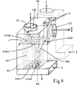
- FIGs. 4 to 7 show an embodiment of a further development of the invention.
- the embodiment looks like the embodiment in Figs. 1 to 3, but there is the difference that the inlet VVA2 to the heat exchanger for the fluid II is not connected to the external inlet A2 but on the contrary is disposed directly in the wall of the heat exchanger which faces a further box device X4 which is most clearly to be seen in Fig. 5, and the inlet A2 is disposed in an outer wall in the further box device K4 which is most clearly seen in Fig. 5.
- the external inlet A3 has been excluded as well as the register 2.
- the inside of the box device K2 is connected to inside of the further box device K4 via an opening A33 placed next to the opening VVA2.
- a wall KK2 in the box device K2.
- a register element 3 which will rather function as a shunt register element 3.
- the fluid II passes through the heat exchanger as indicated by the arrows II in order to absorb recuperation heat from it in the same way as described above when the register 2 is in the position whrere register 2 blocks the inlet A3 and the fluid II is discharged through the output U2 which is now disposed in a side wall in the further box device K4 as shown in Figs. 4 and 5 instead or in a side wall in the box device K2.
- the shunt register element 3 is opened, which is here shown as a louvered register consisting of two vanes rotatable about in the presenet case vertical shafts, the fluid II will pass shuntwise directly from inlet A2 to discharge U2.
- a lesser and lesser proportion of the fluid II will pass the heat exchanger. If this opening is coupled to a simultaneous opening of the above mentioned register 1 at the heat exchanger, a lesser and lesser proportion of the spent air will pass through the heat exchanger for giving off heat. In case no heat recuperation is desired, such as is the case on hot summer days, the registers 1 and 3 are fully opened.
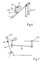
- a register vane US1 the degree of opening of which may be controlled by e.g. a motor M, while a linkage, a chain cr the like which is not shown connects the motor to the register US1.
- Fig. 6 of the drawing there is only shown the respective placement of the registers 1, 3, and US1.
- the registers 1 and 3 may be controlled by servos which are not shown or only a common servo which opens and closes the registers controlled by temperature and moisture conditions.
- a particularly simple transmission linkage beteween the registers it is possible to obtain a quite precise control using only a common drive motor for the registers 1 and 3.
- Such a transmission arrangement is shown in Figs. 6 and 7.
- Fig. 7 actually shows the same as Fig. 6 but only as far as it relates to register US1.
- the registers 1 and 3 follow each other to a suitable degree.
- This degree is adjustable, as the transmission linkage is a simple rod ST, the bearing ends of which are adjustably connected to slots in rotatable arms which are fixed to the registers 1 and 3.
- the transmission linkage is a simple rod ST, the bearing ends of which are adjustably connected to slots in rotatable arms which are fixed to the registers 1 and 3.
- the linkage SU which carries abutment devices SL1 and SL2, between which a rotatable arm connected to or connectable to the drive motor M is slidably carried by and connected to the linkage SU. It is considered that the construction is such that without being hampered by it the linkage SU may and is able to rotate the motor freely, mechanically speaking and at the same time the position of the register US1 has an influence.
- this transmission mechanism ensures that by only a lesser degree of opening of the registers 1 and 3 also the register US1 will be just sufficiently opened not to hamper the necessary passage past US1 of fluid I, in order that the functioning of the heat exchanger is retained as desired controlled by the common adjustment of the registers 1 and 3.
Landscapes
- Engineering & Computer Science (AREA)
- Chemical & Material Sciences (AREA)
- Combustion & Propulsion (AREA)
- Mechanical Engineering (AREA)
- General Engineering & Computer Science (AREA)
- Heat-Exchange Devices With Radiators And Conduit Assemblies (AREA)
Applications Claiming Priority (2)
| Application Number | Priority Date | Filing Date | Title |
|---|---|---|---|
| DK92761A DK76192D0 (da) | 1992-06-09 | 1992-06-09 | Varmeveksler til ventilationsanlaeg |
| DK761/92 | 1992-06-09 |
Publications (1)
| Publication Number | Publication Date |
|---|---|
| EP0575285A1 true EP0575285A1 (en) | 1993-12-22 |
Family
ID=8097260
Family Applications (1)
| Application Number | Title | Priority Date | Filing Date |
|---|---|---|---|
| EP93610035A Withdrawn EP0575285A1 (en) | 1992-06-09 | 1993-06-03 | Heat exchanger for heat recovering ventilation |
Country Status (2)
| Country | Link |
|---|---|
| EP (1) | EP0575285A1 (da) |
| DK (1) | DK76192D0 (da) |
Cited By (2)
| Publication number | Priority date | Publication date | Assignee | Title |
|---|---|---|---|---|
| CN113339992A (zh) * | 2021-06-02 | 2021-09-03 | 中山市骏伟电器有限公司 | 热交换模块及新风机 |
| CN113357731A (zh) * | 2021-06-02 | 2021-09-07 | 中山市骏伟电器有限公司 | 换热新风机 |
Citations (7)
| Publication number | Priority date | Publication date | Assignee | Title |
|---|---|---|---|---|
| USRE26853E (en) * | 1969-03-20 | 1970-04-14 | Room air purifier | |
| US3656542A (en) * | 1970-04-23 | 1972-04-18 | William J Darm | Ventilating system for compartmented buildings |
| DE3217606A1 (de) * | 1981-05-12 | 1982-12-02 | Johannes 7916 Elim Boertien | Waermeaustauscher |
| FR2534357A1 (fr) * | 1982-10-07 | 1984-04-13 | Husson Etu Realisa Aerodynamiq | Perfectionnements apportes aux installations de climatisation, notamment pour locaux d'elevage d'animaux |
| US4512393A (en) * | 1983-04-11 | 1985-04-23 | Baker Colony Farms Ltd. | Heat exchanger core construction and airflow control |
| US4708197A (en) * | 1985-11-01 | 1987-11-24 | Robbins R Ralph | Air to air heat exchanger |
| DE3834440A1 (de) * | 1988-10-10 | 1990-04-12 | Josef Dipl Ing Mollerus | Vorrichtung mit waermerueckgewinnung zur be- und entlueftung von raeumen mit waermeueberschuss |
-
1992
- 1992-06-09 DK DK92761A patent/DK76192D0/da not_active Application Discontinuation
-
1993
- 1993-06-03 EP EP93610035A patent/EP0575285A1/en not_active Withdrawn
Patent Citations (7)
| Publication number | Priority date | Publication date | Assignee | Title |
|---|---|---|---|---|
| USRE26853E (en) * | 1969-03-20 | 1970-04-14 | Room air purifier | |
| US3656542A (en) * | 1970-04-23 | 1972-04-18 | William J Darm | Ventilating system for compartmented buildings |
| DE3217606A1 (de) * | 1981-05-12 | 1982-12-02 | Johannes 7916 Elim Boertien | Waermeaustauscher |
| FR2534357A1 (fr) * | 1982-10-07 | 1984-04-13 | Husson Etu Realisa Aerodynamiq | Perfectionnements apportes aux installations de climatisation, notamment pour locaux d'elevage d'animaux |
| US4512393A (en) * | 1983-04-11 | 1985-04-23 | Baker Colony Farms Ltd. | Heat exchanger core construction and airflow control |
| US4708197A (en) * | 1985-11-01 | 1987-11-24 | Robbins R Ralph | Air to air heat exchanger |
| DE3834440A1 (de) * | 1988-10-10 | 1990-04-12 | Josef Dipl Ing Mollerus | Vorrichtung mit waermerueckgewinnung zur be- und entlueftung von raeumen mit waermeueberschuss |
Cited By (4)
| Publication number | Priority date | Publication date | Assignee | Title |
|---|---|---|---|---|
| CN113339992A (zh) * | 2021-06-02 | 2021-09-03 | 中山市骏伟电器有限公司 | 热交换模块及新风机 |
| CN113357731A (zh) * | 2021-06-02 | 2021-09-07 | 中山市骏伟电器有限公司 | 换热新风机 |
| CN113357731B (zh) * | 2021-06-02 | 2024-03-29 | 中山市骏伟电器有限公司 | 换热新风机 |
| CN113339992B (zh) * | 2021-06-02 | 2025-07-29 | 中山市骏伟电器有限公司 | 热交换模块及新风机 |
Also Published As
| Publication number | Publication date |
|---|---|
| DK76192D0 (da) | 1992-06-09 |
Similar Documents
| Publication | Publication Date | Title |
|---|---|---|
| CA1247450A (en) | Ventilator unit | |
| US4462459A (en) | Device for air control of an energy facade wall | |
| US4562955A (en) | Air-conditioner | |
| US5632334A (en) | Heat recovery ventilator with room air defrosting feature | |
| KR100549206B1 (ko) | 무덕트 방식의 폐열회수 환기시스템 | |
| CZ2001698A3 (cs) | Zařízení na temperování a/nebo větrání prostoru | |
| KR102052348B1 (ko) | 환기장치 | |
| SE508957C2 (sv) | Regenerativ värmeåtervinningsenhet innefattande värmeackumulator som genom en svängningsrörelse uppvisar en spjällfunktion samt värmeåtervinningsaggregat med två ihopkopplade värmeåtervinningsenheter | |
| SE513963C2 (sv) | Ventilations/uppvärmningsenhet | |
| EP0575285A1 (en) | Heat exchanger for heat recovering ventilation | |
| US4803849A (en) | Refrigeration/evaporative cooler unit | |
| CN215808860U (zh) | 立式新风空调室内机 | |
| KR102786488B1 (ko) | 전열교환기 | |
| KR102719010B1 (ko) | 전열교환소자 및 이를 포함하는 전열교환기 | |
| RU2013558C1 (ru) | Шахтная калориферная установка | |
| RU2780117C1 (ru) | Приточно-вытяжная установка для вентиляции по крайней мере одного помещения | |
| JPH07104005B2 (ja) | 空調用床置形換気ユニット | |
| JPH07101112B2 (ja) | 空調用床置形換気ユニット | |
| JPS6396434A (ja) | 空調システム | |
| KR200341143Y1 (ko) | 무덕트 방식의 폐열회수 환기시스템 | |
| JPH0114828Y2 (da) | ||
| PL73692Y1 (pl) | Centrala wentylacyjna | |
| JP2527981Y2 (ja) | 太陽熱利用建築物 | |
| JPH031707Y2 (da) | ||
| DK169111B1 (da) | Friskluftindsugningsventil |
Legal Events
| Date | Code | Title | Description |
|---|---|---|---|
| PUAI | Public reference made under article 153(3) epc to a published international application that has entered the european phase |
Free format text: ORIGINAL CODE: 0009012 |
|
| AK | Designated contracting states |
Kind code of ref document: A1 Designated state(s): AT BE CH DE DK ES FR GB GR IT LI NL PT SE |
|
| 17P | Request for examination filed |
Effective date: 19940617 |
|
| 17Q | First examination report despatched |
Effective date: 19950626 |
|
| STAA | Information on the status of an ep patent application or granted ep patent |
Free format text: STATUS: THE APPLICATION IS DEEMED TO BE WITHDRAWN |
|
| 18D | Application deemed to be withdrawn |
Effective date: 19961015 |