EP0575646A1 - Méthode et dispositif pour former des pièces diverses - Google Patents
Méthode et dispositif pour former des pièces diverses Download PDFInfo
- Publication number
- EP0575646A1 EP0575646A1 EP92110480A EP92110480A EP0575646A1 EP 0575646 A1 EP0575646 A1 EP 0575646A1 EP 92110480 A EP92110480 A EP 92110480A EP 92110480 A EP92110480 A EP 92110480A EP 0575646 A1 EP0575646 A1 EP 0575646A1
- Authority
- EP
- European Patent Office
- Prior art keywords
- workpiece
- zones
- blank
- loading
- sections
- Prior art date
- Legal status (The legal status is an assumption and is not a legal conclusion. Google has not performed a legal analysis and makes no representation as to the accuracy of the status listed.)
- Withdrawn
Links
Images


Classifications
-
- B—PERFORMING OPERATIONS; TRANSPORTING
- B21—MECHANICAL METAL-WORKING WITHOUT ESSENTIALLY REMOVING MATERIAL; PUNCHING METAL
- B21D—WORKING OR PROCESSING OF SHEET METAL OR METAL TUBES, RODS OR PROFILES WITHOUT ESSENTIALLY REMOVING MATERIAL; PUNCHING METAL
- B21D26/00—Shaping without cutting otherwise than using rigid devices or tools or yieldable or resilient pads, i.e. applying fluid pressure or magnetic forces
- B21D26/02—Shaping without cutting otherwise than using rigid devices or tools or yieldable or resilient pads, i.e. applying fluid pressure or magnetic forces by applying fluid pressure
- B21D26/053—Shaping without cutting otherwise than using rigid devices or tools or yieldable or resilient pads, i.e. applying fluid pressure or magnetic forces by applying fluid pressure characterised by the material of the blanks
- B21D26/055—Blanks having super-plastic properties
-
- B—PERFORMING OPERATIONS; TRANSPORTING
- B21—MECHANICAL METAL-WORKING WITHOUT ESSENTIALLY REMOVING MATERIAL; PUNCHING METAL
- B21D—WORKING OR PROCESSING OF SHEET METAL OR METAL TUBES, RODS OR PROFILES WITHOUT ESSENTIALLY REMOVING MATERIAL; PUNCHING METAL
- B21D11/00—Bending not restricted to forms of material mentioned in only one of groups B21D5/00, B21D7/00, B21D9/00; Bending not provided for in groups B21D5/00 - B21D9/00; Twisting
- B21D11/20—Bending sheet metal, not otherwise provided for
-
- B—PERFORMING OPERATIONS; TRANSPORTING
- B21—MECHANICAL METAL-WORKING WITHOUT ESSENTIALLY REMOVING MATERIAL; PUNCHING METAL
- B21D—WORKING OR PROCESSING OF SHEET METAL OR METAL TUBES, RODS OR PROFILES WITHOUT ESSENTIALLY REMOVING MATERIAL; PUNCHING METAL
- B21D37/00—Tools as parts of machines covered by this subclass
- B21D37/16—Heating or cooling
-
- C—CHEMISTRY; METALLURGY
- C21—METALLURGY OF IRON
- C21D—MODIFYING THE PHYSICAL STRUCTURE OF FERROUS METALS; GENERAL DEVICES FOR HEAT TREATMENT OF FERROUS OR NON-FERROUS METALS OR ALLOYS; MAKING METAL MALLEABLE, e.g. BY DECARBURISATION OR TEMPERING
- C21D1/00—General methods or devices for heat treatment, e.g. annealing, hardening, quenching or tempering
-
- C—CHEMISTRY; METALLURGY
- C21—METALLURGY OF IRON
- C21D—MODIFYING THE PHYSICAL STRUCTURE OF FERROUS METALS; GENERAL DEVICES FOR HEAT TREATMENT OF FERROUS OR NON-FERROUS METALS OR ALLOYS; MAKING METAL MALLEABLE, e.g. BY DECARBURISATION OR TEMPERING
- C21D9/00—Heat treatment, e.g. annealing, hardening, quenching or tempering, adapted for particular articles; Furnaces therefor
- C21D9/0006—Details, accessories not peculiar to any of the following furnaces
- C21D9/0025—Supports; Baskets; Containers; Covers
-
- C—CHEMISTRY; METALLURGY
- C21—METALLURGY OF IRON
- C21D—MODIFYING THE PHYSICAL STRUCTURE OF FERROUS METALS; GENERAL DEVICES FOR HEAT TREATMENT OF FERROUS OR NON-FERROUS METALS OR ALLOYS; MAKING METAL MALLEABLE, e.g. BY DECARBURISATION OR TEMPERING
- C21D9/00—Heat treatment, e.g. annealing, hardening, quenching or tempering, adapted for particular articles; Furnaces therefor
- C21D9/46—Heat treatment, e.g. annealing, hardening, quenching or tempering, adapted for particular articles; Furnaces therefor for sheet metals
Definitions
- the present invention relates to plastic metal working and can be used in machine building industry for the manufacture of workpieces from sheets, sections, and monolithic and welded panels forming a working surface of single or double curvature.
- a method is well known in prior art to be used for forming a workpiece under conditions when its material creeps (see, for instance, United States Patent Specification Serial No. 3,739,617).
- a blank is placed on a heated die and pressed thereto over the entire surface thereof by means of a diaphragm. Then the die is heated up uniformly so that it reaches a predetermined temperature.
- the blank is loaded by blowing air into the diaphragm (i.e., by differential pressure) so as to pressurize the diaphragm continuously over the entire surface of the blank until it fits completely the die.
- This purpose is attained by the method of forming a workpiece from a flat blank or a curvilinear blank, wherein it is heated up and loaded under creeping conditions, said method being characterized in that said blank has the surface thereof subdivided into loadings zones, heating zones and cooling zones so that the loading zones are selected therewith depending upon the homogeneity of geometrical parameters and mechanical properties for every particular portion of said blank, whereas the heating zones and the cooling zones are selected depending upon the homogeneity of geometrical parameters and thermal physical properties of every particular portion of said blank.
- the maximum allowable deformations at a predetermined temperature, Ee is determined thereupon, and the value of the latter is used for determining the allowable displacements of the loading points within the boundaries of every loading zone.
- the number of blank deforming steps is determined from the ratio of whereupon the blank is heated up until a predetermined distribution of temperatures is reached within every such zone and then cooled down to have the unevenness of heating density smoothed out. After this, the blank is deformed step by step, the rate of deforming being varied at every step both by heating and by loading under creeping conditions below the limit of elasticity.
- the rate of deforming E T is varied in proportion to the value of e xT
- the rate H of deformation is varied in proportion to the value of ko m
- under the combined influence of heating and loading the deformation rate is varied in proportion to the value of e xT • k ⁇ m
- e natural logarithm base
- x coefficient depending upon the properties of the material used
- T heating temperature
- k coefficient of proportionality
- a deformation stress
- m exponent of power.
- a method of forming and heat-treating a workpiece in accordance with the present invention consists in the following.
- a flat blank or a curvilinear blank is subdivided into zones of deforming.
- the dimensions and configurations of these zones of deforming are to be selected so that the changes in the curvature and rigidity of the workpiece would not exceed appropriate predetermined values within a single particular zone.
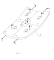
- Fig. 1 shows five of such deforming zones A, B, C, D, and E.
- the main curvature radii R A , R B , R c , R D , and R E vary insignificantly within their appropriate zones.
- An example of workpiece cross- section shown in Fig. 2 comprises three zones A, B, and C.
- the workpiece rigidity is the same within each of these zones.
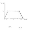
- the heating-conditions are indicated in Fig. 5.
- the predetermined temperature conditions of heating over various zones is ensured by a heat flow radiated by infrared heaters.
- a different density of heat flow is predetermined within each zone.
- the heat flow density is determined in such a manner that the blank temperature would reach 195 °C simultaneously within all the zones in 0.5 hour. If uneven density of heating occurs during heating, the blank should be cooled down to have this unevenness smoothed out.
- the number of deforming steps is determined by us from the following relationship:
- the parameters of influence are established for every zone of the blank, they begin to deform the blank step by step.
- the deformation is carried out both by means of heating and by means of loading under creeping conditions below the limit of elasticity, thus ensuring that plastic deformations will not occur.
- the deforming forces are optimized, for which purpose the rate of deforming is established and varied within every zone in accordance with the emerging stresses.
- the rate of deforming is established and varied within every zone in accordance with the emerging stresses.
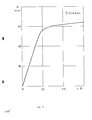
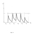
- the value of force is established within each zone which is relaxed to its minimum value (Fig. 6).
- the time of exposure in the loaded state in accordance with the curve of relaxation for this particular material at the temperature selected to be equal to 195 ° C reaches as long as 1.5 hours (Fig. 5).
- this force is reduced down to as low as zero (Fig. 6).
- the geometrical dimensions are maintained as obtained at this particular step of deforming the blank.
- the blank is subjected to heat treatment and to artificial ageing by cooling it down so that the resulting geometrical dimensions are maintained the same, said dimensions being those ones from which a judgement can be made that the predetermined contour of the workpiece is ready.
- the method according to the present invention allows also to produce the workpieces to any predetermined precision grade so that there is no need to size the workpiece any more after the process is carried out. Therewith, not only the manual labour is eliminated completely, but also the distortions are prevented that were possible earlier in the micro and macro structures of the material and could lead to a reduction in the service life of the article.
- a device is well known in prior art to be used for forming a workpiece under creeping conditions of its material in accordance with United States Patent Specification Serial No. 3,739,617.
- this device comprises a die, a diaphragm, a heating arrangement and air supply means.
- the blank is placed on the heatable die and pressed thereto over the entire surface thereof by means of the diaphragm.
- the loading is effected by blowing air into the diaphragm.
- the blank is pressed against the die by exposing the entire sirface of the blank as a whole to the differential pressure.
- a prior art device for forming various workpieces of double curvature under creeping conditions comprising a thermal chamber provided with upper rods and lower rods arranged to be disposed coaxially therein and provided with fixing units in the form of turnable plates shaped as individual parts of the contour as predetermined for the finished workpiece, said device comprising also individual driving members such as screw-and-nut pairs as well as an electric motor (see, for instance, Inventor's Certificate Specification Serial No. 1147471, Int. Cl. B21 D 11/20, i.e., the most relevant prior art).
- the devices described herein above are capable of ensuring only a restricted movement of the parallel rods limited only to one direction - a factor which does not allow to control the deforming of the blank and limits substantially the range of final configurations attainable for the workpieces thus produced.
- the third disadvantage consists in that with emerging over-stresses the necessary deformations lead to the distruction of the micro structure of the workpiece material, thereby laying the causes for the future destruction of the article already into the technology of its manufacture.
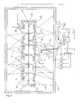
- the method according to the present invention can be implemented by using a device for forming various workpieces, comprising a thermal chamber provided with a heater and also with upper rods and lower rods having driving members and connected to the fixing units for fixing the workpiece, wherein, in conformity with the invention now claimed, said thermal chamber is provided additionally with a multisectional housing which is inserted therein and which has the sections thereof connected pivotally with each other and secured to said fixing units arranged to be disposed at the joints of the sections, said heater being therewith arranged to be disposed in each of said sections, whereas each of said sections is provided with a cooling arrangement inserted therein, and in each of said sections those portions of the workpiece are to be positioned which constitute essentially heating zones, cooling zones and loading zones, said fixing units for fixing the workpiece are provided with spherical pivots through which said fixing units are connected to the driving rods made in the form of hydraulic cylinders attached to the frame of said thermal chamber so that they are swivellable therein, said fixing units serving therewith as the
- the device for the manufacture of the workpieces in accordance with the present invention comprises a thermal chamber 1 provided with a supporting frame on which a heater 2 is arranged to be disposed, said device also comprises driving members 3 with upper and lower rods 4 connected to fixing units 5 for fixing a workpiece 6.
- the fixing unit 5 is provided with a plate 11
- the hydraulic cylinders 3 comprise displacement transducers 12 and load gauges 13 and they are attached to the frame of the thermal chamber so that they are capable of being swivelled therein.
- Each of the sections is provided with a sensor 14 for measuring the temperature and relative deformations therein as well as with a displacement measuring unit 15.
- the latter consists of a spherical pivot with a plate, wherein rods 16 of linear displacement transducers 17 attached pivotally to the wall of the thermal chamber 1 are secured.
- the multisectional housing is provided with grips 18 at the ends thereof for gripping the workpiece 6 thereby.
- All the sensing elements have their outputs connected through normalizers 19 to the appropriate inputs of analog-to-digital converter 20 of a control computing device 21.
- the outputs of the control computing device 21 are connected to an electrohydraulic commutator 22 and to an electrohydraulic transducer 23 which has the pressure and drain pipelines thereof connected to an oil pumping unit 24.
- Another output of the control computing device is connected to electric-power thyristor controllers 25 joined to bus-bars 26 to which the infra-red sources 2 are connected.
- FIG. 7 shows schematically only one thyristor controller, one hydraulic cylinder and one displacement transducer, whereas the positions of all the other elements is indicated by lines.
- the control computing device 21 comprises, besides the multichannel analog-to-digital converter 20, also a micro computer 27, a multichannel digital-to-analog converter 28, output means 29 for reading out the digitized signals, and a control element 30 for controlling the thyristors.
- the device for forming the workpieces in accordance with the present invention operates as follows (Fig. 7 and Fig. 8).
- the multisectional housing 7 is set by means of the rods 4 of the hydraulic cylinders 3 into its initial, for instance, horizontal position so that a clearance is thus ensured in between the fixing units of the upper and lower rods. Then a workpiece 6 is inserted into this clearance and clamped therein by means of the hydraulic cylinder rods.
- the displacement measuring units 15 of the linear displacement transducers 17 and the sensors 14 for measuring the temperature and relative deformations are mounted to the workpiece.
- control computing device 21 regulates the heating temperature of the workpiece 6 within the specified zones, using the thyristor controllers 25 to meter the electric power supplied to the infra-red sources 2. In doing so, use is made of the feedback ensured by the temperature sensors 14.
- control computing device 21 will load and deform the workpiece 6 by the rods 4 of the hydraulic cylinders 3 in accordance with the predetermined program.
- the design of the device now claimed makes it possible to ensure the three-dimensional loading and deformation of the blank due to that several push rods of hydraulic cylinders are united in a single fixing unit through the spherical pivot.
- the push rods of three hydraulic cylinders are united in a fixing unit, it becomes possible to control one normal component of the load and two tangential components of the load as applied to the workpiece.
- the displacements of the workpiece are monitored by the linear displacement transducers 17. If as many as up to three rods of linear displacement transducers are united in a single measuring unit through a spherical pivot, it becomes possible to take the measurements of the normal component and two tangential components of the workpiece displacement. These data are sent through the normalizers 19 and the multichannel analog-to-digital converter 20 to the micro computer 27 which compares the workpiece position against those specified in accordance with the program.
- the micro computer 27 sends appropriate signals to the multichannel analog-to-digital converter 28 and the digitized-signal output means 29 to control the forces developed and the displacements travelled by the push rods 8 of the hydraulic cylinders by means of the electrohydraulic transducer 23 to which the hydraulic cylinders 3 are connected in turn through the electrohydraulic commutator 22. Then, the workpiece thus formed is cooled down by means of the cooling arrangement 9. Every time this occurs, the fixing units maintain the resulting workpiece configuration. The process of forming is terminated as soon as the workpiece reaches its predetermined configuration (Fig. 8).
- the device now claimed ensures the opportunity for independent three-dimensional application of forces and moments, including the forces of tension/compression applied to the workpiece in the median plane, and this opportunity allows to deform the workpieces of complicated configuration with large deflections.
- the thermal chamber frame itself is made in the form of a multisectional housing, some sections of the housing being therewith provided with drives for the displacement thereof in the space, the housing sections of the thermal chamber frame are provided with drives mounted thereto and having rods for loading and deforming the blank directly, each of the sections is provided with heaters and cooling arrangements, whereas the sections are connected with each other by means of pivots.
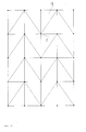
- Fig. 9 illustrates such a device for forming a workpiece with large deflections of the blank.
- the housing of the thermal chamber frame consists of sections 31 provided with drives 32.
- the sections 31 are provided with local short-travel loading devices (or drives) 33 which are attached thereto and which deform the blank of workpiece 6 directly each within its own zone.
- the sections 31 are also provided with heaters 2 and cooling arrangements 9 attached thereto.
- the drives 32 and 33 are provided with displacement transducers and load gauges, and they are connected to the system of control over the process of forming in the same manner as the drives 3 in Fig. 7.
- the process of forming is carried out in accordance with the process described herein above, the loading being carried out within each of the zones by the local short-travel drives 33 within the ranges of their possible travels, whereas the control system 21 compensates for the inadequate rod travel of the local drives 33 by means of moving the sections 31 in the space by the drives 32 so that the sections 31 are positioned equidistantly with respect to the curved surface of the blank of the workpiece 6.
- Such a design of the device according to the present invention allows to carry out forming of the workpieces with rather large deflections of the blank.
- the loads are transmitted to the workpiece in a simpler manner, and the drives can operate easier within the hot zone since only short-travel drives are used here and the direction in which the forces exerted by these local drives are acting will change insignificantly in the process of forming the workpiece.
- the sections 31 may feature a triangular or polygonal configuration in the plan view, thus forming a plurality of approximating flat elements incorporated into a three-dimensional configuration (or a grid), wherein the pivots connecting the sections with each other serve as the units.
- Fig. 10 shows a layout of the sections 31 having a triangular configuration in the plan view and intended for forming a workpiece having a rectangular configuration in the plan view.
- the sections 31 can be connected with each other by means of spherical pivots 34.
- spherical pivots 34 In the most general case for an all-purpose device it is necessary to provide as many pivots 34 and drives 32 for moving the sections 31 as possible so that it would be possible to connect the pivots 34 and the drives 32 as required for working with a particular workpiece 6 depending upon the configuration class of these workpieces.
Landscapes
- Engineering & Computer Science (AREA)
- Mechanical Engineering (AREA)
- Chemical & Material Sciences (AREA)
- Physics & Mathematics (AREA)
- Thermal Sciences (AREA)
- Crystallography & Structural Chemistry (AREA)
- Materials Engineering (AREA)
- Metallurgy (AREA)
- Organic Chemistry (AREA)
- Fluid Mechanics (AREA)
- Shaping Metal By Deep-Drawing, Or The Like (AREA)
- Cosmetics (AREA)
Priority Applications (3)
| Application Number | Priority Date | Filing Date | Title |
|---|---|---|---|
| EP92110480A EP0575646A1 (fr) | 1992-06-22 | 1992-06-22 | Méthode et dispositif pour former des pièces diverses |
| US07/973,104 US5345799A (en) | 1992-06-22 | 1992-11-06 | Method and device for forming various workpieces |
| CA002086579A CA2086579A1 (fr) | 1992-06-22 | 1992-12-31 | Methode et equipement pour former diverses pieces a travailler |
Applications Claiming Priority (1)
| Application Number | Priority Date | Filing Date | Title |
|---|---|---|---|
| EP92110480A EP0575646A1 (fr) | 1992-06-22 | 1992-06-22 | Méthode et dispositif pour former des pièces diverses |
Publications (1)
| Publication Number | Publication Date |
|---|---|
| EP0575646A1 true EP0575646A1 (fr) | 1993-12-29 |
Family
ID=8209733
Family Applications (1)
| Application Number | Title | Priority Date | Filing Date |
|---|---|---|---|
| EP92110480A Withdrawn EP0575646A1 (fr) | 1992-06-22 | 1992-06-22 | Méthode et dispositif pour former des pièces diverses |
Country Status (3)
| Country | Link |
|---|---|
| US (1) | US5345799A (fr) |
| EP (1) | EP0575646A1 (fr) |
| CA (1) | CA2086579A1 (fr) |
Cited By (4)
| Publication number | Priority date | Publication date | Assignee | Title |
|---|---|---|---|---|
| WO1999044765A1 (fr) * | 1998-03-05 | 1999-09-10 | Jong Gye Shin | Machine automatique de formation de pieces incurvees destinees a une coque de bateau |
| EP0904866A3 (fr) * | 1997-09-24 | 2000-08-02 | Mitsubishi Heavy Industries, Ltd. | Système de pliage automatique de tôle avec chauffage par induction à haute fréquence |
| EP0904867A3 (fr) * | 1997-09-29 | 2000-08-02 | Mitsubishi Heavy Industries, Ltd. | Procédé et système pour déterminer le point de chauffage et la ligne de chauffage dans un procédé de pliage d'une tôle |
| WO2002051564A1 (fr) * | 2000-12-23 | 2002-07-04 | Simone Rubbert | Procede de formage de corps plans en objets courbes, irreguliers et multidimensionnels |
Families Citing this family (15)
| Publication number | Priority date | Publication date | Assignee | Title |
|---|---|---|---|---|
| JPH08509660A (ja) * | 1993-02-18 | 1996-10-15 | エス エム エス ハーゼンクレヴァー ゲゼルシャフト ミット ベシュレンクテル ハフツング | 押出しプレスのために規定された金属鋳塊に温度プロフィルを賦与する方法と装置 |
| SE516374C2 (en) * | 2000-02-22 | 2002-01-08 | Workpiece controlled shaping of metal, preferably in the form of plates or bands, comprises heating the workpiece across notches or zones to reduce locally the tensile strength | |
| JP2002241835A (ja) * | 2001-02-20 | 2002-08-28 | Aisin Takaoka Ltd | ワークの部分強化方法 |
| GB2381764A (en) * | 2001-11-08 | 2003-05-14 | Farleydene Ltd | Autoclave suitable for heat treating parts |
| US7637136B2 (en) * | 2002-09-30 | 2009-12-29 | Rinascimetalli Ltd. | Method of working metal, metal body obtained by the method and metal-containing ceramic body obtained by the method |
| GB0229434D0 (en) * | 2002-12-18 | 2003-01-22 | Bae Systems Plc | Aircraft component manufacturing tool and method |
| US7523633B1 (en) * | 2005-10-27 | 2009-04-28 | Mielke Laurence H | Wire tray jig and bending method |
| GB2463642B (en) | 2008-09-17 | 2012-08-29 | Rolls Royce Plc | Press tool arrangement |
| US8607603B2 (en) * | 2010-04-30 | 2013-12-17 | Warsaw Orthopedic, Inc. | Systems, devices and methods for multi-dimensional bending of an elongate member |
| US8298242B2 (en) * | 2010-04-30 | 2012-10-30 | Warsaw Orthopedic, Inc. | Systems, devices and methods for bending an elongate member |
| JP6194526B2 (ja) * | 2013-06-05 | 2017-09-13 | 高周波熱錬株式会社 | 板状ワークの加熱方法及び加熱装置並びにホットプレス成形方法 |
| KR102313910B1 (ko) * | 2017-04-26 | 2021-10-19 | 한국재료연구원 | 연속 공정이 가능한 블로우 성형 장치 |
| CN112427520A (zh) * | 2020-10-26 | 2021-03-02 | 上海凌云汽车模具有限公司 | 一种非常规截型金属件热成型方法和环形工件 |
| CN114472696B (zh) * | 2022-01-25 | 2024-07-19 | 中南大学 | 一种复杂结构大曲率构件精确复合成形方法 |
| US12379180B1 (en) * | 2022-09-13 | 2025-08-05 | Barnett Outdoors, Llc. | Crossbow with de-cocking crank mechanism having sprockets |
Citations (1)
| Publication number | Priority date | Publication date | Assignee | Title |
|---|---|---|---|---|
| US4888973A (en) * | 1988-09-06 | 1989-12-26 | Murdock, Inc. | Heater for superplastic forming of metals |
Family Cites Families (10)
| Publication number | Priority date | Publication date | Assignee | Title |
|---|---|---|---|---|
| US2737224A (en) * | 1951-12-10 | 1956-03-06 | Boeing Co | Apparatus for forming sheet metal |
| US2850071A (en) * | 1954-10-18 | 1958-09-02 | Daniel W Kraybill | Method and apparatus for stretchforming metal and controlling direction of pull |
| US3739617A (en) * | 1970-09-21 | 1973-06-19 | Boeing Co | High temperature vacuum creep forming fixture |
| US3745805A (en) * | 1971-08-27 | 1973-07-17 | Ladish Co | Creep annealing and a multiple pin fixture for use therein |
| FR2237435A5 (fr) * | 1973-07-10 | 1975-02-07 | Aerospatiale | |
| US4212188A (en) * | 1979-01-18 | 1980-07-15 | The Boeing Company | Apparatus for forming sheet metal |
| DE3124514A1 (de) * | 1981-06-23 | 1983-01-05 | Blohm + Voss Ag, 2000 Hamburg | Verfahren zur formgebung von schiffsblechen |
| DE3245755A1 (de) * | 1982-12-10 | 1984-06-14 | Dorstener Maschinenfabrik Ag, 4270 Dorsten | Verfahren zum korrigieren der biegelinie des biegewerkzeuges einer biegepresse, insbesondere abkantpresse |
| JPS6156738A (ja) * | 1984-08-28 | 1986-03-22 | Toyota Motor Corp | 車両用部品の成形方法 |
| US4592537A (en) * | 1985-01-07 | 1986-06-03 | Tocco, Inc. | Apparatus for heat treating and sizing thin walled articles |
-
1992
- 1992-06-22 EP EP92110480A patent/EP0575646A1/fr not_active Withdrawn
- 1992-11-06 US US07/973,104 patent/US5345799A/en not_active Expired - Fee Related
- 1992-12-31 CA CA002086579A patent/CA2086579A1/fr not_active Abandoned
Patent Citations (1)
| Publication number | Priority date | Publication date | Assignee | Title |
|---|---|---|---|---|
| US4888973A (en) * | 1988-09-06 | 1989-12-26 | Murdock, Inc. | Heater for superplastic forming of metals |
Non-Patent Citations (1)
| Title |
|---|
| SOVIET INVENTIONS ILLUSTRATED Section PQ, Week 8541, 22 November 1985 Derwent Publications Ltd., London, GB; AN 85-255013/41 & SU-A-1 147 471 (HYDRO-DYNAMICS) 30 March 1985 * |
Cited By (8)
| Publication number | Priority date | Publication date | Assignee | Title |
|---|---|---|---|---|
| EP0904866A3 (fr) * | 1997-09-24 | 2000-08-02 | Mitsubishi Heavy Industries, Ltd. | Système de pliage automatique de tôle avec chauffage par induction à haute fréquence |
| EP1129798A3 (fr) * | 1997-09-24 | 2001-12-05 | Mitsubishi Heavy Industries, Ltd. | Système de pliage automatique de tôle avec chauffage par induction à haute fréquence |
| EP0904867A3 (fr) * | 1997-09-29 | 2000-08-02 | Mitsubishi Heavy Industries, Ltd. | Procédé et système pour déterminer le point de chauffage et la ligne de chauffage dans un procédé de pliage d'une tôle |
| US6298310B1 (en) | 1997-09-29 | 2001-10-02 | Mitsubishi Heavy Industries, Ltd. | Method and system for determining heating point and heating line in bending of steel plate |
| US6385556B1 (en) | 1997-09-29 | 2002-05-07 | Mitsubishi Heavy Industries, Ltd. | Method and system for determining heating point and heating line in bending of steel plate |
| US6456957B1 (en) | 1997-09-29 | 2002-09-24 | Mitsubishi Heavy Industries, Ltd. | Method and system for determining heating point and heating line in bending of steel plate |
| WO1999044765A1 (fr) * | 1998-03-05 | 1999-09-10 | Jong Gye Shin | Machine automatique de formation de pieces incurvees destinees a une coque de bateau |
| WO2002051564A1 (fr) * | 2000-12-23 | 2002-07-04 | Simone Rubbert | Procede de formage de corps plans en objets courbes, irreguliers et multidimensionnels |
Also Published As
| Publication number | Publication date |
|---|---|
| CA2086579A1 (fr) | 1993-12-23 |
| US5345799A (en) | 1994-09-13 |
Similar Documents
| Publication | Publication Date | Title |
|---|---|---|
| EP0575646A1 (fr) | Méthode et dispositif pour former des pièces diverses | |
| AU2007209756B2 (en) | Active reconfigurable stretch forming | |
| US6071360A (en) | Controlled strain rate forming of thick titanium plate | |
| CN104646475A (zh) | 铝合金飞机整体壁板多点成形方法 | |
| JPH10166059A (ja) | 板の曲げ加工方法 | |
| CN118335415B (zh) | 一种线缆生产用加热设备的控制方法及加热系统 | |
| Leem et al. | A toolpath strategy for double-sided incremental forming of corrugated structures | |
| US20030116219A1 (en) | Method and apparatus for setting a helical compression spring | |
| Wang et al. | A novel mechanical attachment for biaxial tensile test: Application to formability evaluation for DP590 at different temperatures | |
| US5519623A (en) | Improved bending machine and a method for bending a part | |
| EP2578331B1 (fr) | Procédé et équipement de mise en forme d'un composant coulé | |
| RU2056197C1 (ru) | Способ формообразования деталей и устройство для его осуществления | |
| US3344968A (en) | Trimming glass sheets | |
| JPH0262349B2 (fr) | ||
| JP2920372B2 (ja) | エイジフォーミング成形方法 | |
| CN113954393B (zh) | 一种复合材料构件分区加热固化变形控制方法 | |
| JPH11179428A (ja) | 鋼材の加熱曲げ加工方法および装置 | |
| RU2856527C1 (ru) | Способ двухсторонней роботизированной формовки с использованием двух однотипных инструментов | |
| CN112969541A (zh) | 使用感应加热使物体成型的方法和系统 | |
| RU2106251C1 (ru) | Устройство для вакуумно-автоклавного формования панелей из полимерных композиционных материалов | |
| CN111847852B (zh) | 龙虾眼光学器件球面成形系统与方法 | |
| JP3575926B2 (ja) | 折曲げ機における折曲げ角度補正方法および補正装置 | |
| KR20180067010A (ko) | 금속판에 다양한 곡면을 성형하는 방법 | |
| SU967613A1 (ru) | Способ формообразовани деталей | |
| CN120562051A (zh) | 一种框类钛合金结构件热校形载荷的计算方法 |
Legal Events
| Date | Code | Title | Description |
|---|---|---|---|
| PUAI | Public reference made under article 153(3) epc to a published international application that has entered the european phase |
Free format text: ORIGINAL CODE: 0009012 |
|
| AK | Designated contracting states |
Kind code of ref document: A1 Designated state(s): AT BE CH DE ES FR GB IT LI NL SE |
|
| K1C3 | Correction of patent application (complete document) published |
Effective date: 19931229 |
|
| 17P | Request for examination filed |
Effective date: 19940608 |
|
| 17Q | First examination report despatched |
Effective date: 19941114 |
|
| STAA | Information on the status of an ep patent application or granted ep patent |
Free format text: STATUS: THE APPLICATION IS DEEMED TO BE WITHDRAWN |
|
| 18D | Application deemed to be withdrawn |
Effective date: 19950525 |