EP0575648A1 - Milieu de pression pour un appareil à système hydraulique fermé - Google Patents
Milieu de pression pour un appareil à système hydraulique fermé Download PDFInfo
- Publication number
- EP0575648A1 EP0575648A1 EP92110509A EP92110509A EP0575648A1 EP 0575648 A1 EP0575648 A1 EP 0575648A1 EP 92110509 A EP92110509 A EP 92110509A EP 92110509 A EP92110509 A EP 92110509A EP 0575648 A1 EP0575648 A1 EP 0575648A1
- Authority
- EP
- European Patent Office
- Prior art keywords
- pressure medium
- silicone
- pressure
- weight
- medium according
- Prior art date
- Legal status (The legal status is an assumption and is not a legal conclusion. Google has not performed a legal analysis and makes no representation as to the accuracy of the status listed.)
- Withdrawn
Links
- 229920001296 polysiloxane Polymers 0.000 claims abstract description 45
- 150000001875 compounds Chemical class 0.000 claims abstract description 28
- OKTJSMMVPCPJKN-UHFFFAOYSA-N Carbon Chemical compound [C] OKTJSMMVPCPJKN-UHFFFAOYSA-N 0.000 claims abstract description 16
- 239000012530 fluid Substances 0.000 claims abstract description 15
- 229920002631 room-temperature vulcanizate silicone Polymers 0.000 claims abstract description 12
- 239000004945 silicone rubber Substances 0.000 claims abstract description 12
- 239000011521 glass Substances 0.000 claims abstract description 11
- 239000000203 mixture Substances 0.000 claims abstract description 10
- 239000000843 powder Substances 0.000 claims abstract description 10
- 239000000463 material Substances 0.000 claims abstract description 8
- 239000004205 dimethyl polysiloxane Substances 0.000 claims abstract description 6
- 235000013870 dimethyl polysiloxane Nutrition 0.000 claims abstract description 6
- 229920000435 poly(dimethylsiloxane) Polymers 0.000 claims abstract description 6
- 239000010439 graphite Substances 0.000 abstract description 5
- 229910002804 graphite Inorganic materials 0.000 abstract description 5
- 239000010720 hydraulic oil Substances 0.000 description 6
- 239000003921 oil Substances 0.000 description 6
- 229920001971 elastomer Polymers 0.000 description 5
- 239000002480 mineral oil Substances 0.000 description 5
- 238000012360 testing method Methods 0.000 description 5
- 238000010586 diagram Methods 0.000 description 4
- 238000013461 design Methods 0.000 description 3
- 230000009969 flowable effect Effects 0.000 description 3
- 235000010446 mineral oil Nutrition 0.000 description 3
- 239000000654 additive Substances 0.000 description 2
- 229920002379 silicone rubber Polymers 0.000 description 2
- 238000012512 characterization method Methods 0.000 description 1
- 230000006835 compression Effects 0.000 description 1
- 238000007906 compression Methods 0.000 description 1
- 239000000806 elastomer Substances 0.000 description 1
- 239000000945 filler Substances 0.000 description 1
- 238000012986 modification Methods 0.000 description 1
- 230000004048 modification Effects 0.000 description 1
- 238000000465 moulding Methods 0.000 description 1
- 238000012856 packing Methods 0.000 description 1
- 238000000518 rheometry Methods 0.000 description 1
- 150000003377 silicon compounds Chemical class 0.000 description 1
- 238000012546 transfer Methods 0.000 description 1
Images


Classifications
-
- C—CHEMISTRY; METALLURGY
- C08—ORGANIC MACROMOLECULAR COMPOUNDS; THEIR PREPARATION OR CHEMICAL WORKING-UP; COMPOSITIONS BASED THEREON
- C08K—Use of inorganic or non-macromolecular organic substances as compounding ingredients
- C08K3/00—Use of inorganic substances as compounding ingredients
- C08K3/02—Elements
- C08K3/04—Carbon
-
- C—CHEMISTRY; METALLURGY
- C08—ORGANIC MACROMOLECULAR COMPOUNDS; THEIR PREPARATION OR CHEMICAL WORKING-UP; COMPOSITIONS BASED THEREON
- C08K—Use of inorganic or non-macromolecular organic substances as compounding ingredients
- C08K3/00—Use of inorganic substances as compounding ingredients
- C08K3/40—Glass
Definitions
- This invention relates to a new and useful pressure medium for hydraulically functioning tools and apparatuses, such as chucks, workpiece-holders or mechanical seals.
- the new pressure medium is essentially meant for purposes where thermal expansion of hydraulic fluid causes excessive pressure or where high compressibility causes long piston movements.
- the silicone pressure medium as such and hydraulic oils have as a drawback high thermal expansion, which can cause excessive pressure rise in an apparatus using such pressure medium.
- Another drawback is high compressibility, which can cause too long movement of the piston used to pressurize said pressure medium.
- the thermal expansion causes e.g. in hydraulic oil 70 bar/10°C pressure rise, which means that the pressure rise is so high, that said apparatus would break if temperature rise is 150°C, or if said apparatus is provided with temperature compensating means, e.g. a spring loaded piston, the movement of the piston and springs would be too long to be useful in existing equipment.
- Still another drawback when using hydraulic oil is that under the great pressure leaks are very common.
- one important aspect of the present invention is to avoid oil leaks and the use of expensive seal designs and to achieve a new pressure medium which is useful where wide temperature range is required.
- the new pressure medium according to the invention is characterized by what is presented in the characterization part of the claims.
- the main advantages of the invention include a reduction of the thermal expansion, a reduction of compressibility of the silicone compound and a possibility to avoid leaks of the hydraulic fluid used. Also the flowability of the compound improves.
- the thermal expansion is relatively high, as shown in fig. 1, which means that the pressure increase in closed systems is often too high requiring design provisions to avoid excessive pressure rise.
- the inclined line “1 bar” indicates the increase of the volume of a certain mineral oil as a function of temperature when the volume can freely increase.
- the space for the oil is not closed.
- the volume increase in a free space with the oil in question is about 6.6% (106.6) when the temperature increases 100°C. If the space for the oil is limited in this particular case so that with 100°C temperature increase the volume of the oil can increase only about 4.6% the pressure increases 500 bar.
- the lowest line “1500 bar” indicates the situation where the possibility of volume increase is still more limited.
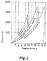
- silicone fluids are higher than that of mineral oils, as clearly shown in figure 2.
- a mineral oil 100°C increase of temperature corresponds about 5% increase of volume but in a closed space this causes the pressure of 1000 bar.
- a silicone 100°C temperature increase tends to cause 10% increase of volume which in a closed space causes the same pressure of 1000 bar.
- the invention relates to a new pressure medium for a closed hydraulic apparatus, wherein the pressure medium comprises silicone compounds mixed with graphite and/or glasspowder for reducing the coefficient of thermal expansion.
- the new improved pressure medium comprises a silicone mixture including an RTV silicone rubber (room temperature vulcanizing silicone) and a silicone fluid (dimethyl polysiloxane).
- the silicone compound used can comprise only a room temperature vulcanizing (RTV) silicone rubber or a mixture of a RTV silicone rubber and a silicone fluid (dimethyl polysiloxane).
- RTV room temperature vulcanizing
- the pressure medium comprises a mixture of silicone compounds including 10-30 % by weight of a silicone fluid and 90-70 % by weight of an RTV silicone rubber.
- RTV silicone vulcanizes at room temperature in a certain time but it can vulcanized faster at higher temperatures. Later in the description both the abovementioned alternatives are referred as silicone compound.
- the silicon compound can be filled with graphite powder or glass powder or with a mixture of the both of them. Later in the description all the abovementioned alternatives are referred as filling material.
- the suitable mixing ratio is in the range from 10 to 60 % by weight of the filling material.
- the pressure medium comprises the silicone compound mixed with 10-60 % by weight of graphite powder and 30-10 % by weight of glass powder.
- One way of producing the pressure medium is to use the silicone fluid (dimethyl polysiloxane) only mixed with graphite powder. Also this kind of compound is sufficiently flowable.
- the pressure medium there is more than one way to fill the pressure chamber with the silicone compound mixed with the filling material. This mixture is called the pressure medium.
- One way is to mix the filling material into the silicone compound and then cast the produced pressure medium into the pressure chamber, close the pressure chamber and vulcanize the pressure medium either at room temperature or at higher temperature.
- Another way is to mix the filling material into the silicone compound and then cast the produced pressure medium into a mold and vulcanize the pressure medium either at room temperature or at higher temperature. Only thereafter the pressure medium is compressed into the pressure chamber.
- FIGS 3 and 4 are shown compressibility of two different pressure mediums manufactured according to the teaching of the present invention.
- the pressure medium of fig. 3, (622G) comprises 55 % by weight of RTV silicone rubber and 45 % by weight of graphite powder.
- the pressure medium of fig. 4, (622L) comprises 40 % by weight of RTV silicone rubber, 10 % by weight of silicone fluid (dimethyl polysiloxane) and 50 % by weight of glass powder.
- the rheology of the pressure medium according to the present invention was studied by using cylindrical test pieces having diameter of 20 mm and length of 20 mm.
- the test pieces were compressed through different size nozzle orifices being 20 mm in length and having diameters 2 mm, 4 mm or 6mm.
- the force needed to compress test pieces through the different orifices were measured and the results are shown in fig. 5.
- the material indicated by 622 comprises 100 by weight of RTV silicone rubber.
- the addition of graphite powder and/or glass powder to the silicone compounds reduced the needed compression force compared to the pure silicone compound (622), as is clearly shown in figure 5.
- Cured rubber having for example mixing ratio of 50 % graphite powder and 50 % silicone compounds, all percentages by weight, is compressed into a pressure chamber.
- a hydraulic piston For the compressing of the pressure medium through a small hole e.g. a hydraulic piston can be used. Large batches of silicone and additives are best mixed with a mechanical stirrer, but kneadable compounds can be mixed by hand.
- Air free pressure medium is easily achieved with filling apparatus when air escapes from a threaded hole provided in the pressure chamber which hole is closed after the pressure chamber is full of pressure medium.
- graphite and/or glass additives are chemically inert.
Landscapes
- Chemical & Material Sciences (AREA)
- Health & Medical Sciences (AREA)
- Chemical Kinetics & Catalysis (AREA)
- Medicinal Chemistry (AREA)
- Polymers & Plastics (AREA)
- Organic Chemistry (AREA)
- Compositions Of Macromolecular Compounds (AREA)
Priority Applications (1)
| Application Number | Priority Date | Filing Date | Title |
|---|---|---|---|
| EP92110509A EP0575648A1 (fr) | 1992-06-22 | 1992-06-22 | Milieu de pression pour un appareil à système hydraulique fermé |
Applications Claiming Priority (1)
| Application Number | Priority Date | Filing Date | Title |
|---|---|---|---|
| EP92110509A EP0575648A1 (fr) | 1992-06-22 | 1992-06-22 | Milieu de pression pour un appareil à système hydraulique fermé |
Publications (1)
| Publication Number | Publication Date |
|---|---|
| EP0575648A1 true EP0575648A1 (fr) | 1993-12-29 |
Family
ID=8209737
Family Applications (1)
| Application Number | Title | Priority Date | Filing Date |
|---|---|---|---|
| EP92110509A Withdrawn EP0575648A1 (fr) | 1992-06-22 | 1992-06-22 | Milieu de pression pour un appareil à système hydraulique fermé |
Country Status (1)
| Country | Link |
|---|---|
| EP (1) | EP0575648A1 (fr) |
Citations (6)
| Publication number | Priority date | Publication date | Assignee | Title |
|---|---|---|---|---|
| DE3039692A1 (de) * | 1979-10-25 | 1981-05-07 | Instytut Chemii Przemysłowej, Warszawa | Mechanische energie absorbierende polysiloxan-kompositionen |
| EP0233134A1 (fr) * | 1986-02-13 | 1987-08-19 | United Technologies Corporation | Méthode et appareil pour le moulage utilisant un polymère solide et fluide |
| EP0260216A2 (fr) * | 1986-09-10 | 1988-03-16 | United Technologies Corporation | Milieu solide, fluide à base d'un polymère et son emploi dans un procédé de moulage |
| EP0270899A2 (fr) * | 1986-12-08 | 1988-06-15 | Dow Corning Corporation | Procédé de moulage isostatique utilisant un polysiloxane friable comme milieu hydraulique |
| EP0273264A2 (fr) * | 1986-12-19 | 1988-07-06 | Dow Corning Corporation | Composition d'organopolysiloxane à l'état friable, utilisable comme matériau hydraulique et ayant une stabilité thermique améliorée |
| WO1991004814A1 (fr) * | 1989-10-03 | 1991-04-18 | Unicraft Oy | Dispositif de fixation reglable |
-
1992
- 1992-06-22 EP EP92110509A patent/EP0575648A1/fr not_active Withdrawn
Patent Citations (6)
| Publication number | Priority date | Publication date | Assignee | Title |
|---|---|---|---|---|
| DE3039692A1 (de) * | 1979-10-25 | 1981-05-07 | Instytut Chemii Przemysłowej, Warszawa | Mechanische energie absorbierende polysiloxan-kompositionen |
| EP0233134A1 (fr) * | 1986-02-13 | 1987-08-19 | United Technologies Corporation | Méthode et appareil pour le moulage utilisant un polymère solide et fluide |
| EP0260216A2 (fr) * | 1986-09-10 | 1988-03-16 | United Technologies Corporation | Milieu solide, fluide à base d'un polymère et son emploi dans un procédé de moulage |
| EP0270899A2 (fr) * | 1986-12-08 | 1988-06-15 | Dow Corning Corporation | Procédé de moulage isostatique utilisant un polysiloxane friable comme milieu hydraulique |
| EP0273264A2 (fr) * | 1986-12-19 | 1988-07-06 | Dow Corning Corporation | Composition d'organopolysiloxane à l'état friable, utilisable comme matériau hydraulique et ayant une stabilité thermique améliorée |
| WO1991004814A1 (fr) * | 1989-10-03 | 1991-04-18 | Unicraft Oy | Dispositif de fixation reglable |
Similar Documents
| Publication | Publication Date | Title |
|---|---|---|
| CA1083617A (fr) | Amortisseur de choc a elastomere fluide | |
| US4011929A (en) | Dampening device using a silicone rubber | |
| EP0453701B1 (fr) | Cartouche amortisseur | |
| JPS6250512B2 (fr) | ||
| US5869750A (en) | Method, system and device for testing two-phase compressible compositions having gas under pressure | |
| US4704240A (en) | Method of fabricating tubular composite structures | |
| KR101419956B1 (ko) | 고무 조성물, 그 제조 방법, 고무 조성물을 이용한 시일재 및 이것을 구비한 장치, 및 내dme용 고무 조성물 | |
| CA1288882C (fr) | Silicone emiette pour l'hydraulique | |
| CA1206990A (fr) | Joint ou garniture a doublure, et sa fabrication | |
| JPH0698636B2 (ja) | 物品の成形方法及び装置 | |
| EP0575648A1 (fr) | Milieu de pression pour un appareil à système hydraulique fermé | |
| US2646595A (en) | Method for molding omicron-ring gaskets | |
| EP0569158B1 (fr) | Support fluidique pour les hautes températures | |
| WO1995020111A1 (fr) | Ressort a liquide pour presse de decoupage | |
| US5580917A (en) | Hydrostatically damping shock and vibration energy absorbing non-vulcanizable silicone elastomer | |
| JPH0693279A (ja) | 改良された圧力媒体 | |
| JPH06505553A (ja) | パッキングの製造方法及びパッキング | |
| CA1287435C (fr) | Produit solide et coulant a base de polymere pour le moulage | |
| US4772437A (en) | Method of molding using a solid flowable polymer medium with U.V. detectable additive | |
| EP2534392B1 (fr) | Ressort à gaz muni d'un moyen d'étanchéité amélioré | |
| JP5621133B2 (ja) | 制振用組成物 | |
| FI81180C (fi) | Hydraulisk eller pneumatisk kraftanordning. | |
| JPH0559348A (ja) | 気密を保持して摺動するシール材用のパツキング | |
| EP0270899B1 (fr) | Procédé de moulage isostatique utilisant un polysiloxane friable comme milieu hydraulique | |
| CA1113890A (fr) | Methode de pre-telescopage d'un dispositif d'attelage |
Legal Events
| Date | Code | Title | Description |
|---|---|---|---|
| PUAI | Public reference made under article 153(3) epc to a published international application that has entered the european phase |
Free format text: ORIGINAL CODE: 0009012 |
|
| AK | Designated contracting states |
Kind code of ref document: A1 Designated state(s): CH DE ES FR GB IT LI SE |
|
| STAA | Information on the status of an ep patent application or granted ep patent |
Free format text: STATUS: THE APPLICATION IS DEEMED TO BE WITHDRAWN |
|
| 18D | Application deemed to be withdrawn |
Effective date: 19940630 |