EP0575652A1 - Transmission à réduction - Google Patents
Transmission à réduction Download PDFInfo
- Publication number
- EP0575652A1 EP0575652A1 EP92110692A EP92110692A EP0575652A1 EP 0575652 A1 EP0575652 A1 EP 0575652A1 EP 92110692 A EP92110692 A EP 92110692A EP 92110692 A EP92110692 A EP 92110692A EP 0575652 A1 EP0575652 A1 EP 0575652A1
- Authority
- EP
- European Patent Office
- Prior art keywords
- intermediate ring
- wheel
- drive wheel
- planet
- reduction gear
- Prior art date
- Legal status (The legal status is an assumption and is not a legal conclusion. Google has not performed a legal analysis and makes no representation as to the accuracy of the status listed.)
- Withdrawn
Links
Images


Classifications
-
- F—MECHANICAL ENGINEERING; LIGHTING; HEATING; WEAPONS; BLASTING
- F16—ENGINEERING ELEMENTS AND UNITS; GENERAL MEASURES FOR PRODUCING AND MAINTAINING EFFECTIVE FUNCTIONING OF MACHINES OR INSTALLATIONS; THERMAL INSULATION IN GENERAL
- F16H—GEARING
- F16H1/00—Toothed gearings for conveying rotary motion
- F16H1/28—Toothed gearings for conveying rotary motion with gears having orbital motion
- F16H1/32—Toothed gearings for conveying rotary motion with gears having orbital motion in which the central axis of the gearing lies inside the periphery of an orbital gear
-
- F—MECHANICAL ENGINEERING; LIGHTING; HEATING; WEAPONS; BLASTING
- F16—ENGINEERING ELEMENTS AND UNITS; GENERAL MEASURES FOR PRODUCING AND MAINTAINING EFFECTIVE FUNCTIONING OF MACHINES OR INSTALLATIONS; THERMAL INSULATION IN GENERAL
- F16H—GEARING
- F16H49/00—Other gearings
- F16H49/001—Wave gearings, e.g. harmonic drive transmissions
-
- F—MECHANICAL ENGINEERING; LIGHTING; HEATING; WEAPONS; BLASTING
- F16—ENGINEERING ELEMENTS AND UNITS; GENERAL MEASURES FOR PRODUCING AND MAINTAINING EFFECTIVE FUNCTIONING OF MACHINES OR INSTALLATIONS; THERMAL INSULATION IN GENERAL
- F16H—GEARING
- F16H25/00—Gearings comprising primarily only cams, cam-followers and screw-and-nut mechanisms
- F16H25/04—Gearings comprising primarily only cams, cam-followers and screw-and-nut mechanisms for conveying rotary motion
- F16H25/06—Gearings comprising primarily only cams, cam-followers and screw-and-nut mechanisms for conveying rotary motion with intermediate members guided along tracks on both rotary members
- F16H2025/066—Gearings comprising primarily only cams, cam-followers and screw-and-nut mechanisms for conveying rotary motion with intermediate members guided along tracks on both rotary members the intermediate members being rollers supported in a chain
Definitions
- the invention relates to a reduction gear with an input shaft and with a coaxial output shaft, with a drive wheel arranged on the input shaft, with an output wheel arranged on the output shaft, which has outward transmission elements, with an intermediate ring interacting with both wheels, the inward transmission elements has and is held eccentrically circular in engagement with the driven gear rotation.
- a reduction gear of this type can be found - installed in a cable winch - for example in US Pat. No. 2,495,811.
- the driven gear represents a flange of the cable drum and is provided with an external ring gear in which an internal ring gear of the eccentrically rotating intermediate ring engages. Its drive takes place via the drive wheel arranged eccentrically on the drive shaft, on which the intermediate ring is rotatably mounted.
- the eccentrically circling intermediate ring is held against rotation on the housing by a radially protruding, sliding and rotatably mounted arm.
- the reduction ratio is determined by the difference in the number of teeth of the driven gear and the intermediate ring.
- the invention has now set itself the task of creating a reduction gear in which a higher reduction ratio can be achieved with the same wheel diameters or number of teeth.
- the drive wheel is arranged concentrically on the drive shaft and is provided with outwardly directed transmission elements, and in that at least one planet wheel engaging in the transmission elements of the drive wheel and the intermediate ring is provided, which protrudes outward over the circumference of the driven wheel.
- the intermediate ring At the area of engagement between the intermediate ring and the driven gear diametrically opposite Side, i.e. in the direction of the common radius of the drive wheel and the intermediate ring, the intermediate ring has the greatest distance from the drive wheel due to the eccentricity, so that a single planet gear inserted at this point has the greatest possible projection and is therefore fixed in its position.
- each planet gear rolls between the drive gear and the intermediate ring.
- the function of a cam or an eccentric is achieved by the projection of the planet gear over the driven gear, and the intermediate ring is continuously displaced outwards by the planet gear in the direction of rotation of the drive shaft and eccentrically rotating due to the rotation-free holder.
- the drive shaft is balanced by the elimination of an eccentric and in addition there is a reduction between the drive shaft and the intermediate ring, so that the overall reduction is increased.
- An advantageous embodiment is provided when the two planet gears are arranged diametrically opposite one another and each have approximately half the projection. As a result, the unbalanced gear parts are limited to the intermediate ring, since this also distributes the two planet wheels evenly.
- a first embodiment which is particularly suitable for the use of a single planet gear, provides that the drive gear and the intermediate ring have U-shaped or V-shaped grooves, and each planet gear has a circumferential web engaging in the grooves.
- Another embodiment which is particularly suitable for the use of two planet gears, provides that all transmission elements have teeth.
- the planet gears are preferably inserted loosely and are neither arranged on a carrier nor on bearing axles, so that the transmission has an extremely simple structure.
- the arrangement of a carrier which is rotatably mounted on the drive shaft is also possible. If only a single planet gear or two non-diametrically opposed planet gears are used, the carrier can also serve as a mass balance for the planet gears and be shaped accordingly.
- a particularly inexpensive manufacture of the reduction gear results when the toothing of the drive wheel and the intermediate ring are formed by closed roller chains, and the driven gear and each planet gear are designed as sprockets.
- Reduction gears with different reduction ratios despite the same outer dimensions of the intermediate ring and the driven gear can be achieved in that the drive gear is exchangeably attached to the drive shaft and different sizes of drive gears and associated planet gears are available. It is essential that the sum of the radius of the drive wheel and the diameter of the planet gear is constant.
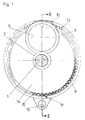
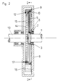
- FIGS. 3 and 4 show a radial and an axial section through a first embodiment and FIGS. 3 and 4 the same sections through a second embodiment.
- a reduction gear has an input shaft 1 and a coaxial output shaft 13, which are each mounted in a housing 8.
- a drive wheel 2 is optionally exchangeably arranged or designed to be exchangeable, which has transmission elements directed outwards.
- An output gear 14 is also equipped with external transmission elements, which is arranged centrally and rotatably on the output shaft 13.
- the two wheels 2, 14 are surrounded by an intermediate ring 9, the diameter of which is larger than that of the driven wheel 14 and which is arranged eccentrically to the two shafts 1, 13.
- the circular movement of the intermediate ring 9 is brought about via at least one planet wheel 5 which engages in the drive wheel 2 and which also engages in the intermediate ring 9 and projects beyond the circumference of the driven wheel 14.
- each planet gear 5 runs on a circular path around the drive shaft 1 due to its interventions in the drive wheel 2 and the intermediate ring 9 and in the process urges the intermediate ring 9 outwards, so that the engagement region 17 moves.
- the circumference of the drive wheel 2 is smaller than the inner circumference of the intermediate ring 9, a first reduction stage results between the drive wheel 2 and the intermediate ring 9.
- the size of the reduction can be determined by suitable selection of the drive wheel 2 and the planet gear 5 or the planet gears 5.
- the planet gear 5 the directions of rotation of the input shaft 1 and the output shaft 2 are the same.
- a single planet gear 5 is formed by a disk with the largest possible diameter in the direction of the common radius of the drive gear 2 and the intermediate ring 9, which has a circumferential web 6 which is bevelled on both sides.
- the associated transmission elements of the drive wheel 2 and the intermediate ring 9 each consist of a U- or V-shaped groove 3, 10, in which the opposite shaped circumferential web 6 of the planet gear 5 engages.
- the second row of transmission elements on the inside of the intermediate ring 9 comprises a toothing 12 formed by a closed roller chain, in which the teeth 15 of the driven gear 14 designed as a chain gear engage in the region 17, which is diametrically opposite the planet gear 5.
- two planet gears 5 are provided which, compared to the single planet gear 5 of FIGS. 1 and 2, each have a smaller diameter by half the eccentricity and are arranged diametrically opposite one another symmetrically to the common radius.
- toothings 4, 7, 11, 12, 15 are provided as transmission elements.
- the drive wheel 2 is enclosed by a roller chain and two individual roller chains or a double roller chain are arranged in the intermediate ring 9. Accordingly, both planet gears 5 and the driven gear 14 are designed as sprockets.
- the planet gears 5 are loosely inserted between the drive wheel 2 and the intermediate ring 9 and require neither a carrier nor bearing axles. However, it is possible to provide a planet gear carrier on the drive shaft 1 so that it can rotate freely, on which each planet gear 5 is freely rotatably mounted. 1 and 2, a planet gear carrier can also be used as a mass balance, which is not necessary in the embodiment according to FIGS. 3 and 4.
Landscapes
- Engineering & Computer Science (AREA)
- General Engineering & Computer Science (AREA)
- Mechanical Engineering (AREA)
- Retarders (AREA)
Priority Applications (1)
| Application Number | Priority Date | Filing Date | Title |
|---|---|---|---|
| EP92110692A EP0575652A1 (fr) | 1992-06-26 | 1992-06-26 | Transmission à réduction |
Applications Claiming Priority (1)
| Application Number | Priority Date | Filing Date | Title |
|---|---|---|---|
| EP92110692A EP0575652A1 (fr) | 1992-06-26 | 1992-06-26 | Transmission à réduction |
Publications (1)
| Publication Number | Publication Date |
|---|---|
| EP0575652A1 true EP0575652A1 (fr) | 1993-12-29 |
Family
ID=8209743
Family Applications (1)
| Application Number | Title | Priority Date | Filing Date |
|---|---|---|---|
| EP92110692A Withdrawn EP0575652A1 (fr) | 1992-06-26 | 1992-06-26 | Transmission à réduction |
Country Status (1)
| Country | Link |
|---|---|
| EP (1) | EP0575652A1 (fr) |
Citations (6)
| Publication number | Priority date | Publication date | Assignee | Title |
|---|---|---|---|---|
| US1641656A (en) * | 1923-05-29 | 1927-09-06 | John S Barnett | Planetary transmission gearing |
| FR2025039A1 (fr) * | 1968-12-02 | 1970-09-04 | Bendix Corp | |
| US4478100A (en) * | 1982-03-08 | 1984-10-23 | Sfredda Albert P | Automatic transmission |
| US4481842A (en) * | 1981-08-31 | 1984-11-13 | Wedgtrac Corporation | Torque limit drive transmission |
| US4620455A (en) * | 1985-02-08 | 1986-11-04 | Excelermatic Inc. | Traction roller transmission |
| EP0307732A2 (fr) * | 1987-09-04 | 1989-03-22 | TBS GmbH | Transmission |
-
1992
- 1992-06-26 EP EP92110692A patent/EP0575652A1/fr not_active Withdrawn
Patent Citations (6)
| Publication number | Priority date | Publication date | Assignee | Title |
|---|---|---|---|---|
| US1641656A (en) * | 1923-05-29 | 1927-09-06 | John S Barnett | Planetary transmission gearing |
| FR2025039A1 (fr) * | 1968-12-02 | 1970-09-04 | Bendix Corp | |
| US4481842A (en) * | 1981-08-31 | 1984-11-13 | Wedgtrac Corporation | Torque limit drive transmission |
| US4478100A (en) * | 1982-03-08 | 1984-10-23 | Sfredda Albert P | Automatic transmission |
| US4620455A (en) * | 1985-02-08 | 1986-11-04 | Excelermatic Inc. | Traction roller transmission |
| EP0307732A2 (fr) * | 1987-09-04 | 1989-03-22 | TBS GmbH | Transmission |
Similar Documents
| Publication | Publication Date | Title |
|---|---|---|
| DE69305380T2 (de) | Reihe drehzahlsteigernder und -senkender Getriebe unter Verwendung einer Getriebekonstruktion nach dem Zykloidenprinzip | |
| DE2554467A1 (de) | Orbitalgetriebe | |
| DE4239331A1 (fr) | ||
| DE2315746A1 (de) | Spannungswellenerzeuger und diesen verwendende spannungswellenantriebsanordnung | |
| EP0551050A1 (fr) | Transmission excentrique | |
| DE102007015289B4 (de) | Oszillierendes innen eingreifendes Planetenradreduktionsgetriebe | |
| DE102017128637A1 (de) | Untersetzungsgetriebe | |
| DE19548568C2 (de) | Differentialgetriebe mit Abstützung der Ausgleichsräder | |
| DE4013196A1 (de) | Differentialgetriebe | |
| DE2507844A1 (de) | Intermittierender drehmechanismus | |
| WO2005047043A1 (fr) | Boite de transfert a couronnes dentees | |
| DE19714528A1 (de) | Umlaufgetriebe | |
| DE4126866C2 (fr) | ||
| DE102014213151B4 (de) | Kreisschiebeplanetenradgetriebe | |
| EP0248289A2 (fr) | Transmission d'engrenage avec rapport de changement de vitesse variable continûment | |
| DE1960503B2 (de) | Umlaufgetriebe mit exzentren | |
| EP3653905B1 (fr) | Engrenage excentrique | |
| EP0575652A1 (fr) | Transmission à réduction | |
| DE19518160A1 (de) | Planetengetriebe | |
| DE3040383A1 (de) | Untersetzungsgetriebe | |
| DE3719006C2 (fr) | ||
| DE29705170U1 (de) | Untersetzungsgetriebe | |
| DE19731004A1 (de) | Rückkehrendes Umlaufgetriebe | |
| DE102017106767A1 (de) | Kegelradgetriebe mit integriertem Planetengetriebe-Differential | |
| DD157880A5 (de) | Vorrichtung zum aufnehmen einer schlauchfolie |
Legal Events
| Date | Code | Title | Description |
|---|---|---|---|
| PUAI | Public reference made under article 153(3) epc to a published international application that has entered the european phase |
Free format text: ORIGINAL CODE: 0009012 |
|
| AK | Designated contracting states |
Kind code of ref document: A1 Designated state(s): AT BE CH DE DK ES FR GB GR IT LI LU MC NL PT SE |
|
| RBV | Designated contracting states (corrected) |
Designated state(s): AT CH DE FR GB IT LI SE |
|
| STAA | Information on the status of an ep patent application or granted ep patent |
Free format text: STATUS: THE APPLICATION IS DEEMED TO BE WITHDRAWN |
|
| 18D | Application deemed to be withdrawn |
Effective date: 19940630 |