EP0575700A1 - Méthode et dispositif pour appliquer une tension à un moteur de traction à courant continu - Google Patents
Méthode et dispositif pour appliquer une tension à un moteur de traction à courant continu Download PDFInfo
- Publication number
- EP0575700A1 EP0575700A1 EP93104024A EP93104024A EP0575700A1 EP 0575700 A1 EP0575700 A1 EP 0575700A1 EP 93104024 A EP93104024 A EP 93104024A EP 93104024 A EP93104024 A EP 93104024A EP 0575700 A1 EP0575700 A1 EP 0575700A1
- Authority
- EP
- European Patent Office
- Prior art keywords
- voltage
- value
- function
- specified
- voltage value
- Prior art date
- Legal status (The legal status is an assumption and is not a legal conclusion. Google has not performed a legal analysis and makes no representation as to the accuracy of the status listed.)
- Withdrawn
Links
Images


Classifications
-
- B—PERFORMING OPERATIONS; TRANSPORTING
- B60—VEHICLES IN GENERAL
- B60L—PROPULSION OF ELECTRICALLY-PROPELLED VEHICLES; SUPPLYING ELECTRIC POWER FOR AUXILIARY EQUIPMENT OF ELECTRICALLY-PROPELLED VEHICLES; ELECTRODYNAMIC BRAKE SYSTEMS FOR VEHICLES IN GENERAL; MAGNETIC SUSPENSION OR LEVITATION FOR VEHICLES; MONITORING OPERATING VARIABLES OF ELECTRICALLY-PROPELLED VEHICLES; ELECTRIC SAFETY DEVICES FOR ELECTRICALLY-PROPELLED VEHICLES
- B60L15/00—Methods, circuits, or devices for controlling the traction-motor speed of electrically-propelled vehicles
- B60L15/10—Methods, circuits, or devices for controlling the traction-motor speed of electrically-propelled vehicles for automatic control superimposed on human control to limit the acceleration of the vehicle, e.g. to prevent excessive motor current
-
- B—PERFORMING OPERATIONS; TRANSPORTING
- B60—VEHICLES IN GENERAL
- B60L—PROPULSION OF ELECTRICALLY-PROPELLED VEHICLES; SUPPLYING ELECTRIC POWER FOR AUXILIARY EQUIPMENT OF ELECTRICALLY-PROPELLED VEHICLES; ELECTRODYNAMIC BRAKE SYSTEMS FOR VEHICLES IN GENERAL; MAGNETIC SUSPENSION OR LEVITATION FOR VEHICLES; MONITORING OPERATING VARIABLES OF ELECTRICALLY-PROPELLED VEHICLES; ELECTRIC SAFETY DEVICES FOR ELECTRICALLY-PROPELLED VEHICLES
- B60L15/00—Methods, circuits, or devices for controlling the traction-motor speed of electrically-propelled vehicles
- B60L15/20—Methods, circuits, or devices for controlling the traction-motor speed of electrically-propelled vehicles for control of the vehicle or its driving motor to achieve a desired performance, e.g. speed, torque, programmed variation of speed
-
- B—PERFORMING OPERATIONS; TRANSPORTING
- B60—VEHICLES IN GENERAL
- B60L—PROPULSION OF ELECTRICALLY-PROPELLED VEHICLES; SUPPLYING ELECTRIC POWER FOR AUXILIARY EQUIPMENT OF ELECTRICALLY-PROPELLED VEHICLES; ELECTRODYNAMIC BRAKE SYSTEMS FOR VEHICLES IN GENERAL; MAGNETIC SUSPENSION OR LEVITATION FOR VEHICLES; MONITORING OPERATING VARIABLES OF ELECTRICALLY-PROPELLED VEHICLES; ELECTRIC SAFETY DEVICES FOR ELECTRICALLY-PROPELLED VEHICLES
- B60L2250/00—Driver interactions
- B60L2250/26—Driver interactions by pedal actuation
-
- Y—GENERAL TAGGING OF NEW TECHNOLOGICAL DEVELOPMENTS; GENERAL TAGGING OF CROSS-SECTIONAL TECHNOLOGIES SPANNING OVER SEVERAL SECTIONS OF THE IPC; TECHNICAL SUBJECTS COVERED BY FORMER USPC CROSS-REFERENCE ART COLLECTIONS [XRACs] AND DIGESTS
- Y02—TECHNOLOGIES OR APPLICATIONS FOR MITIGATION OR ADAPTATION AGAINST CLIMATE CHANGE
- Y02T—CLIMATE CHANGE MITIGATION TECHNOLOGIES RELATED TO TRANSPORTATION
- Y02T10/00—Road transport of goods or passengers
- Y02T10/60—Other road transportation technologies with climate change mitigation effect
- Y02T10/64—Electric machine technologies in electromobility
-
- Y—GENERAL TAGGING OF NEW TECHNOLOGICAL DEVELOPMENTS; GENERAL TAGGING OF CROSS-SECTIONAL TECHNOLOGIES SPANNING OVER SEVERAL SECTIONS OF THE IPC; TECHNICAL SUBJECTS COVERED BY FORMER USPC CROSS-REFERENCE ART COLLECTIONS [XRACs] AND DIGESTS
- Y02—TECHNOLOGIES OR APPLICATIONS FOR MITIGATION OR ADAPTATION AGAINST CLIMATE CHANGE
- Y02T—CLIMATE CHANGE MITIGATION TECHNOLOGIES RELATED TO TRANSPORTATION
- Y02T10/00—Road transport of goods or passengers
- Y02T10/60—Other road transportation technologies with climate change mitigation effect
- Y02T10/72—Electric energy management in electromobility
Definitions
- the invention relates to a method for applying a voltage to a DC traction motor, in particular for industrial trucks, according to the preamble of claim 1.
- a DC motor is normally used for this purpose, the terminals of which are supplied with battery voltage.
- the voltage applied to the engine determines the moment on the drive wheel of the vehicle and thus its acceleration or speed.
- the effective voltage level is set by a suitable pulse circuit, the control signal for the pulse circuit being derived from a signal which is generated by the driving switch.
- the invention has for its object to provide a method for applying a voltage to a DC traction motor, especially for industrial trucks, with which the starting behavior is improved while protecting the mechanical drive parts.
- a uniform voltage function for example in the form of an ascending straight line, is not selected, but one from two sections existing function, the first section beginning with zero has a large slope and the second section has a smaller slope.
- the functional sections preferably consist of straight lines. They are chosen so that the intermediate voltage value, which for example can already be 70% of the battery voltage, is reached in a very short time, for example in 10 to 20% of the predetermined period for the entire time in which the full voltage is applied to the motor becomes. The larger the predetermined time period, the smaller the slope of the first functional section and at the same time the intermediate voltage value forming the end of the first functional section.
- an embodiment of the invention provides that two or more voltage functions are provided with different time spans and different intermediate voltage values, which are selected arbitrarily by the driver of the vehicle or automatically depending on the weight of the vehicle, such that the voltage function with the larger one increases with increasing weight Period and the smaller intermediate voltage value can be selected.
- the individual voltage or ramp functions can be stored in a table in a memory, for example an EPROM. The driver can arbitrarily use some of the ramp functions if this is provided.
- a load sensor can also be provided so that a specific ramp function is selected depending on the load size.
- a large number of ramp functions can be stored in the memory, in which case the user can make a selection as to which ramp functions are optimal for the intended operation of the vehicle.
- the ramp function It is no problem for the person skilled in the art to determine the ramp function. It is chosen so that the maximum permissible torque of a component or a maximum permissible acceleration of the vehicle is not exceeded.
- the weakest link in the drive chain determines this limit or the specification of the user.
- the voltage curve is otherwise selected so that the time required to build up the drive torque is minimized below the maximum permissible drive torque.
- a battery 10 feeds a DC motor 14 via a control circuit 12, which drives a wheel 18 of a vehicle, for example an industrial truck, via a gear 16.
- the control circuit 12 is connected to a travel switch 20 which is operated by the driver. The deflection on the travel switch determines the proportion of the battery voltage U B that is applied to the motor 14.
- the voltage is designated U S in FIG. 1.
- the travel switch generates a voltage signal U F depending on its position, for example via a potentiometer.
- the engine 14 generates an engine torque M M or transmission input torque. The output torque of the transmission 16 M G is transferred to the wheel.
- the drive switch 20 If the drive switch 20 is operated slowly, it follows the voltage applied to the motor U S directly corresponds to the driving switch voltage U F. If this also applied to a sudden adjustment of the driving switch, for example from 0 to 100%, the battery voltage U B would be applied suddenly to the motor 14. As already stated, this mode of operation is unfavorable because it leads to a torque that is too high and, in particular, places excessive stress on the mechanical parts, not including the unfavorable acceleration behavior of the vehicle. It is therefore known to provide a converter in the control circuit 12 which, in the event of a sudden change in the driving switch voltage U F, gives the battery voltage to the motor 14 after a time function.
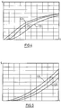
- the ramp function 3 in the form of a straight line, as is shown in FIG. 2 with the reference numerals 1 and 2.
- the linear voltage ramps 1 and 2 reach the voltage at which the contactors are switched in order to connect the battery 10 directly to the terminals of the motor 14 at different times, for example at 0.7 and 1.3 seconds.
- the voltage when switching the contactors makes a small jump. This is based on the losses of the control circuit 12, which are eliminated when the battery voltage U B is directly applied to the motor 14.
- the ramp function 3 according to FIG. 2 is provided, which consists of a first straight functional section 3a and consists of a second straight functional section 3b.
- the first section 3a which begins at the zero point, has a large slope. It reaches 70% of the battery voltage U B within a very short time, for example at 10% of the contactor switching time t R.
- the intermediate voltage value reached is denoted by U Z.
- the second ramp section 3b extends from the intermediate voltage value U Z with a significantly smaller slope. If the torque profiles for the voltage ramps according to FIG. 2 are now compared, the torque profiles according to FIG. 3 result.
- a limit torque M M is shown in FIG. 3, which characterizes the maximum input torque for the transmission 16. It can be seen that in the case of a voltage ramp 1 with a relatively short contactor switching time t r, a maximum for the torque curve is reached which is above the limit torque.
- the voltage ramp 1 cannot be used for the limit torque M M. Only the voltage ramp 2 reaches a maximum which is below the limit value M M. The maximum of the torque curve for the voltage ramp 3 is approximately the same as that for the voltage ramp 2, but is achieved in a much shorter time. You can also see that the torque is almost constant up to the contactor switching time t r . Using the voltage ramp 3 therefore accelerates the vehicle, speaks faster and the vehicle acceleration is more even (this will be discussed further below). The transmission is also protected.
- FIG. 4 shows the speed profile of the vehicle or the path profile for voltage ramps 1, 2 and 3. This also results in the advantageous acceleration for a vehicle when it is driven according to voltage ramp 3 in run-up mode.
- the functional sections 3a and 3b can be described by the following equations: with 0 ⁇ t ⁇ P X. t R , where a represents the losses of the control circuit 12, P Y the intermediate voltage value in percent of the final voltage value and P X the time in which the intermediate voltage value is reached in percent of the contactor switching time t r . with P X t r ⁇ t ⁇ t r .
- the functional sections 3a, 3b of the voltage ramp are selected as a function of the system, that is to say as a function of the vehicle, in such a way that the maximum permissible torque of a drive component or a maximum permissible acceleration of the vehicle is not exceeded.
- the voltage curve, in particular the first functional section 3a is then selected such that the time t r required to build up the maximum permissible drive torque is as short as possible. Compared to conventional switching times, which are between 0.5 and 2 seconds, short switching times of 0.1 to 0.2 seconds are now possible, which means maximum acceleration without damaging drive components and ergonomically favorable driving behavior.
- the voltage ramp 3 can be stored in a table in an EPROM.
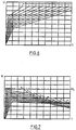
- a family of voltage ramps which meet the above conditions but lead to different starting behavior.
- Such a ramp family is shown in Fig. 6. They correspond to the family of torque curves according to FIG. 7.
- the user selects one of the voltage ramps 6 from which the vehicle is then operated.
- the voltage ramps can be optimized depending on the load. For example, a voltage ramp for the vehicle empty weight, for an average weight and for a maximum weight can be provided.
- a load sensor can be coupled to the vehicle, the signal of which is sent to the control circuit 12.
Landscapes
- Engineering & Computer Science (AREA)
- Power Engineering (AREA)
- Transportation (AREA)
- Mechanical Engineering (AREA)
- Electric Propulsion And Braking For Vehicles (AREA)
Applications Claiming Priority (2)
| Application Number | Priority Date | Filing Date | Title |
|---|---|---|---|
| DE4220277 | 1992-06-20 | ||
| DE4220277A DE4220277C2 (de) | 1992-06-20 | 1992-06-20 | Verfahren und Vorrichtung zum Anlegen einer Spannung an einen Gleichstrom-Fahrmotor |
Publications (1)
| Publication Number | Publication Date |
|---|---|
| EP0575700A1 true EP0575700A1 (fr) | 1993-12-29 |
Family
ID=6461482
Family Applications (1)
| Application Number | Title | Priority Date | Filing Date |
|---|---|---|---|
| EP93104024A Withdrawn EP0575700A1 (fr) | 1992-06-20 | 1993-03-12 | Méthode et dispositif pour appliquer une tension à un moteur de traction à courant continu |
Country Status (2)
| Country | Link |
|---|---|
| EP (1) | EP0575700A1 (fr) |
| DE (1) | DE4220277C2 (fr) |
Cited By (6)
| Publication number | Priority date | Publication date | Assignee | Title |
|---|---|---|---|---|
| FR2720699A1 (fr) * | 1994-06-06 | 1995-12-08 | Sagem | Procédé de commande d'un moteur de véhicule à confort amélioré. |
| FR2720698A1 (fr) * | 1994-06-06 | 1995-12-08 | Sagem | Procédé de commande d'un moteur de véhicule. |
| FR2720697A1 (fr) * | 1994-06-06 | 1995-12-08 | Sagem | Procédé de commande à sensibilité améliorée d'un moteur de véhicule à propulsion électrique. |
| FR2721560A1 (fr) * | 1994-06-24 | 1995-12-29 | Sagem | Procédé de commande d'un moteur de véhicule à propulsion électrique. |
| WO1997036763A1 (fr) * | 1996-03-29 | 1997-10-09 | Frank John Thompson Hancock | Dispositif de commande |
| US5789884A (en) * | 1996-03-25 | 1998-08-04 | Hancock; Frank John Thompson | Control arrangement for motorised trolley |
Families Citing this family (1)
| Publication number | Priority date | Publication date | Assignee | Title |
|---|---|---|---|---|
| DE19629386C1 (de) * | 1996-07-20 | 1998-01-29 | Jungheinrich Ag | Elektrischer Fahrantrieb für ein Flurförderzeug |
Citations (1)
| Publication number | Priority date | Publication date | Assignee | Title |
|---|---|---|---|---|
| EP0374960A2 (fr) * | 1988-12-23 | 1990-06-27 | Hitachi, Ltd. | Dispositif de contrôle du matériel roulant électrique |
Family Cites Families (3)
| Publication number | Priority date | Publication date | Assignee | Title |
|---|---|---|---|---|
| DE1186136B (de) * | 1962-06-07 | 1965-01-28 | Licentia Gmbh | Verfahren und Sollwertgeber zur Sollwertvorgabe bei der Drehzahlregelung eines elektromotorischen Antriebs |
| US3543113A (en) * | 1968-03-06 | 1970-11-24 | Westinghouse Electric Corp | Load weight circuit for traction motor control systems |
| US3543121A (en) * | 1968-03-06 | 1970-11-24 | Westinghouse Electric Corp | Jerk limit circuit for traction motor control systems |
-
1992
- 1992-06-20 DE DE4220277A patent/DE4220277C2/de not_active Expired - Fee Related
-
1993
- 1993-03-12 EP EP93104024A patent/EP0575700A1/fr not_active Withdrawn
Patent Citations (1)
| Publication number | Priority date | Publication date | Assignee | Title |
|---|---|---|---|---|
| EP0374960A2 (fr) * | 1988-12-23 | 1990-06-27 | Hitachi, Ltd. | Dispositif de contrôle du matériel roulant électrique |
Non-Patent Citations (1)
| Title |
|---|
| PATENT ABSTRACTS OF JAPAN vol. 005, no. 097 (M-075)24. Juni 1981 & JP-A-56 041 702 ( HITACHI, LTD ) 18. April 1981 * |
Cited By (6)
| Publication number | Priority date | Publication date | Assignee | Title |
|---|---|---|---|---|
| FR2720699A1 (fr) * | 1994-06-06 | 1995-12-08 | Sagem | Procédé de commande d'un moteur de véhicule à confort amélioré. |
| FR2720698A1 (fr) * | 1994-06-06 | 1995-12-08 | Sagem | Procédé de commande d'un moteur de véhicule. |
| FR2720697A1 (fr) * | 1994-06-06 | 1995-12-08 | Sagem | Procédé de commande à sensibilité améliorée d'un moteur de véhicule à propulsion électrique. |
| FR2721560A1 (fr) * | 1994-06-24 | 1995-12-29 | Sagem | Procédé de commande d'un moteur de véhicule à propulsion électrique. |
| US5789884A (en) * | 1996-03-25 | 1998-08-04 | Hancock; Frank John Thompson | Control arrangement for motorised trolley |
| WO1997036763A1 (fr) * | 1996-03-29 | 1997-10-09 | Frank John Thompson Hancock | Dispositif de commande |
Also Published As
| Publication number | Publication date |
|---|---|
| DE4220277C2 (de) | 1995-10-12 |
| DE4220277A1 (de) | 1993-12-23 |
Similar Documents
| Publication | Publication Date | Title |
|---|---|---|
| DE19721093C2 (de) | Fahrzeug mit Drehkraft übertragenden Armen zum Befahren von Treppen | |
| DE4402423B4 (de) | Servolenkungs-Vorrichtung für Motorfahrzeuge | |
| DE4401333A1 (de) | Fahrzeuglenkung-Steuersystem | |
| EP0584457A1 (fr) | Procédé et dispositif pour régler l'engagement et le disengagement d'un embrayage dans la transmission d'un véhicule | |
| DE4327483A1 (de) | Verfahren und Vorrichtung zur Ansteuerung eines Leistungsstellelements einer Antriebseinheit eines Fahrzeugs | |
| DE2714113C2 (de) | Einrichtung zum Regeln der Fahrgeschwindigkeit eines Kraftfahrzeugs | |
| DE19644881B4 (de) | Verfahren und Vorrichtung zur Steuerung eines Ausgangsdrehmoments eines Triebstrangs eines Fahrzeugs | |
| DE69903502T2 (de) | Elektrisch betätigte Getriebeschalteinrichtung mit Kondensator | |
| EP0575700A1 (fr) | Méthode et dispositif pour appliquer une tension à un moteur de traction à courant continu | |
| DE2930439C2 (de) | Überlastsicherung für ein Hebezeug | |
| EP0069922A2 (fr) | Procédé de commande de boîtes de vitesses automatiques dans des véhicules automobiles | |
| DE3421387C2 (fr) | ||
| DE602004004617T2 (de) | Positionswähleinrichtung für ein automatisches Getriebe | |
| EP2193061A2 (fr) | Procédé et dispositif pour influer sur la force de traction pendant des processus de changement de vitesses d'une boîte de vitesses mécanique | |
| DE19537273A1 (de) | Einrichtung zur Geschwindigkeitsregelung von Fahrzeugen | |
| EP3219584A1 (fr) | Procédé destiné au moins à la mise en stationnement semi-automatique d'un véhicule automobile, système d'aide au conducteur et véhicule automobile | |
| DE102007011509A1 (de) | Lenksystem mit Mitteln zur Bewertung der auftretenden Lenkmomente | |
| DE10210795A1 (de) | Fahrverhaltensumschaltung | |
| DE3844286A1 (de) | Sicherheits-notlaufverfahren fuer kraftfahrzeuge und vorrichtung zu seiner durchfuehrung | |
| EP0802467A2 (fr) | Méthode et moyens pour le positionnement d'un appareil | |
| DE102017108473A1 (de) | Verfahren zur Kontrolle eines elektrischen Antriebs eines Fahrzeugs | |
| DE4242169C2 (de) | Geschwindigkeitsregler | |
| EP0578919B1 (fr) | Dispositif à courant continu d'entraînement pour véhicules, notamment pour véhicules de manutention | |
| EP0256268A1 (fr) | Limitateur du nombre de tours pour moteurs de véhicule | |
| EP1955925B1 (fr) | Procédé destiné au fonctionnement d'un système de direction dans un véhicule automobile |
Legal Events
| Date | Code | Title | Description |
|---|---|---|---|
| PUAI | Public reference made under article 153(3) epc to a published international application that has entered the european phase |
Free format text: ORIGINAL CODE: 0009012 |
|
| AK | Designated contracting states |
Kind code of ref document: A1 Designated state(s): DE FR GB IT SE |
|
| 17P | Request for examination filed |
Effective date: 19940616 |
|
| 17Q | First examination report despatched |
Effective date: 19951215 |
|
| 18D | Application deemed to be withdrawn |
Effective date: 19970205 |
|
| 18D | Application deemed to be withdrawn |
Effective date: 19970205 |