EP0575718A1 - Dispositif pour égaliser une pile - Google Patents
Dispositif pour égaliser une pile Download PDFInfo
- Publication number
- EP0575718A1 EP0575718A1 EP93106197A EP93106197A EP0575718A1 EP 0575718 A1 EP0575718 A1 EP 0575718A1 EP 93106197 A EP93106197 A EP 93106197A EP 93106197 A EP93106197 A EP 93106197A EP 0575718 A1 EP0575718 A1 EP 0575718A1
- Authority
- EP
- European Patent Office
- Prior art keywords
- bumper
- pushing
- straight
- stack
- stacking direction
- Prior art date
- Legal status (The legal status is an assumption and is not a legal conclusion. Google has not performed a legal analysis and makes no representation as to the accuracy of the status listed.)
- Granted
Links
Images



Classifications
-
- B—PERFORMING OPERATIONS; TRANSPORTING
- B65—CONVEYING; PACKING; STORING; HANDLING THIN OR FILAMENTARY MATERIAL
- B65H—HANDLING THIN OR FILAMENTARY MATERIAL, e.g. SHEETS, WEBS, CABLES
- B65H31/00—Pile receivers
- B65H31/34—Apparatus for squaring-up piled articles
- B65H31/38—Apparatus for vibrating or knocking the pile during piling
-
- B—PERFORMING OPERATIONS; TRANSPORTING
- B65—CONVEYING; PACKING; STORING; HANDLING THIN OR FILAMENTARY MATERIAL
- B65H—HANDLING THIN OR FILAMENTARY MATERIAL, e.g. SHEETS, WEBS, CABLES
- B65H2402/00—Constructional details of the handling apparatus
- B65H2402/60—Coupling, adapter or locking means
-
- B—PERFORMING OPERATIONS; TRANSPORTING
- B65—CONVEYING; PACKING; STORING; HANDLING THIN OR FILAMENTARY MATERIAL
- B65H—HANDLING THIN OR FILAMENTARY MATERIAL, e.g. SHEETS, WEBS, CABLES
- B65H2511/00—Dimensions; Position; Numbers; Identification; Occurrences
- B65H2511/10—Size; Dimensions
-
- Y—GENERAL TAGGING OF NEW TECHNOLOGICAL DEVELOPMENTS; GENERAL TAGGING OF CROSS-SECTIONAL TECHNOLOGIES SPANNING OVER SEVERAL SECTIONS OF THE IPC; TECHNICAL SUBJECTS COVERED BY FORMER USPC CROSS-REFERENCE ART COLLECTIONS [XRACs] AND DIGESTS
- Y10—TECHNICAL SUBJECTS COVERED BY FORMER USPC
- Y10S—TECHNICAL SUBJECTS COVERED BY FORMER USPC CROSS-REFERENCE ART COLLECTIONS [XRACs] AND DIGESTS
- Y10S414/00—Material or article handling
- Y10S414/10—Associated with forming or dispersing groups of intersupporting articles, e.g. stacking patterns
- Y10S414/12—Associated with forming or dispersing groups of intersupporting articles, e.g. stacking patterns including means pressing against top or end of group
Definitions
- the invention relates to a device for straight pushing a stack with a bumper pointing in the stacking direction, at the end pointing in the stacking direction, a bumper plate is arranged, and with a displaceable in the pushing direction, connected to carry out the pushing movement with drive means in which to adjust the position of the Bumper plate relative to the bracket, the bumper for format adjustment is slidably mounted in the stacking direction and its position is adjustable.
- Such a device is known from DE-GM 75 13 266.
- plates attached to straight bumpers are pushed towards and then moved away again for straight butting.
- This back and forth movement is transmitted by a cam drive to a bearing bush that is displaceable relative to the machine side frame.
- a positionable linear bumper designed as a spindle, is adjustably mounted in its position.
- the straight bumper is moved in its position with respect to the bearing bush.
- such a straight bumper In order to enable format adjustment over a larger area, such a straight bumper must be designed as long as possible.
- the invention is based on the problem of creating a device for straight butting a stack according to the preamble of the main claim, with which a secure format adjustment over a wide format adjustment range is possible in a space-saving manner.
- this problem is solved by an embodiment of such a device according to the characterizing features of claim 1.
- a small sheet format with a large length of the straight bumper can be processed.
- processing with a short length of the straight bumper is possible.
- the straight bumper does not represent an additional safety risk for people, additional, space-consuming and obstructing cladding can be omitted.
- An embodiment according to the features of claim 2 represents a particularly simple preferred embodiment, in which a functionally reliable stack alignment over a large format adjustment range can be carried out with little effort is possible. Stable storage can be maintained across the entire format range.
- the training according to the features of claim 3 enables a particularly advantageous and safe format adjustment.
- the inventive design according to the features of claim 4 represents a particularly simple space-saving design of a device for pushing a stack straight.
- the straight bumper With a common drive means, the straight bumper can be adjusted in its position for holding and its length can be changed.
- the inventive device according to the features of claim 5 allows a simple design of the means for changing the length of the straight bumper. Since the means for changing the length participate in the straight butt movement in such a device, they can be in permanent operative connection with the straight bumper without additional, expensive, extensive coupling elements.
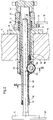
- FIGS. 1 to 6 The invention is explained in more detail below using an exemplary embodiment, as shown in FIGS. 1 to 6.
- Fig. 1 shows a last printing unit 2 downstream in the sheet conveying direction 1 of a sheetfed offset printing press, in which the paper sheets placed on a delivery stack 3 are secured by means of brackets 40 attached to racks arranged in the side walls 5 in the stacking direction, with straight bumper plates 4 articulated thereon in its lateral side Position.
- the profiled rack 15 is slidably mounted in a hollow shaft 14.
- the hollow shaft 14 is provided in its lower region with a longitudinal groove 39 formed parallel to its axis, the two ends of which are formed as stop surfaces 18 and 19.
- the hollow shaft 14 is rotatably axially displaceable in a bearing bush 6 fastened in the side wall 5 and also axially displaceably, rotatably mounted hollow shaft 7.
- the two hollow shafts 7 and 14 and the rack 15 are arranged concentrically.
- the hollow shaft 14 is profiled on its outer circumference and in a bushing 16 fastened in the hollow shaft 7 with the outer profile of the hollow shaft 14 Correspondingly designed inner profile rotatably mounted axially.
- a bearing block 23 is fastened on the end region of the hollow shaft 7 pointing from the side wall 5 to the stack side.
- an adjusting shaft 25 is rotatably and axially fixed beneath the rack 15.
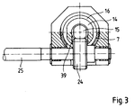
- a gearwheel 24 is attached to the adjusting shaft 25 and meshes with the rack 25 through a longitudinal groove of the hollow shaft 7 and through the longitudinal groove 37.
- the adjusting shaft 25 is aligned perpendicular to the axis of the rack 15 and rotatably, axially fixed at its end opposite the gear 24 in a bearing bush 29.
- the bearing bush 29 is mounted in a slot 28, which is designed as a sliding bearing, on a holding projection 27, which is fastened to the side wall 5, so that it can be displaced in a rotationally fixed manner parallel to the rack axis.
- a handwheel 26 is fastened on the adjusting shaft 25.
- the adjusting shaft 25 can be locked in a set rotational position with respect to the bearing bush 29 by means of a locking screw 30.
- a driving plate 8 is fastened on the end of the hollow shaft 7 that points away from the delivery stack 3 through the side wall 5.
- a driving roller 9 is rotatably mounted radially to the hollow shaft 7.
- a compression spring 10 is mounted concentrically with the hollow shaft 7 between the drive plate 8 and the bearing bush 6.
- the roller 9 is in constant contact with the compression spring 10 with an axial cam segment disc 11 driven by the printing press drive in a known manner about a pivot pin 12 of a lever 13 in a reciprocating movement.
- the locking screw 30 is first loosened, then the handwheel 26 and thus the gearwheel 24 are rotated, as a result of which the toothed rack 15 is displaced in its axial position. If the sheet format is reduced, the rack 15 is shifted in its position towards the sheet stack with entrainment of the hollow shaft 14 until the stop 18 of the hollow shaft 14 strikes the end face of the guide bush 16. When the gear wheel 24 is rotated further, the gear rack 15 is now displaced with respect to the hollow shaft 14 in the direction of the stack until the end region 20 of the gear rack 15 reaches the meshing region of the gear wheel 24.
- the gear wheel is rotated in the opposite direction, whereby the rack 15 is first pushed away from the sheet stack, taking the hollow shaft 14 with it, until the stop 19 of the hollow shaft 14 strikes a stop, not shown, on the facing end face of the hollow shaft 7 outside the area of influence of the gear wheel 24.
- the gear wheel 24 is rotated further, the toothed rack 15 is displaced away from the sheet stack with respect to the hollow shaft 14 until the straight arc joint holder 40 strikes the end face of the hollow shaft 14.
- the handwheel 25 is locked again using the clamping screw 30. For this phase-wise entrainment of the hollow shaft 14, lower frictional forces act between the hollow shaft 14 and the hollow shaft 7 than between the hollow shaft 14 and the rack 15.
- the slot 28 is designed so that a sliding movement of the bearing bush 29 relative to the Bracket 27 over the entire intended stroke range of the straight butt plate 4 is made possible.
- a pneumatic cylinder 32 with a piston rod 33 radially aligned with the hollow shaft 7 can be fastened to a holding projection 31 on the outside of the side wall 5 on the outside of the side wall 5.
- a lever 35 on a bearing pin 34 is on the piston rod 33 pivoted.
- the lever 35 is double-armed and is pivotally mounted with its one arm about a pivot pin 36, which is fastened in the retaining projection 31.
- the other arm of the lever 35 is formed with a right-angled stop 37 which corresponds to a right-angled stop surface 38, consisting of a stop surface which faces away from the side wall 5 and a circumferential surface.
- a hollow shaft-shaped pin 41 can have its end face on the end face pointing away from the side wall 5 the drive plate 8 are pressed mechanically, electrically or pneumatically and push them out of the area of influence of the curve segment.
Landscapes
- Engineering & Computer Science (AREA)
- Mechanical Engineering (AREA)
- Pile Receivers (AREA)
- Supply, Installation And Extraction Of Printed Sheets Or Plates (AREA)
- Sheets, Magazines, And Separation Thereof (AREA)
Applications Claiming Priority (2)
| Application Number | Priority Date | Filing Date | Title |
|---|---|---|---|
| DE4220074 | 1992-06-19 | ||
| DE4220074A DE4220074A1 (de) | 1992-06-19 | 1992-06-19 | Vorrichtung zum Geradstoßen eines Stapels |
Publications (2)
| Publication Number | Publication Date |
|---|---|
| EP0575718A1 true EP0575718A1 (fr) | 1993-12-29 |
| EP0575718B1 EP0575718B1 (fr) | 1995-07-26 |
Family
ID=6461371
Family Applications (1)
| Application Number | Title | Priority Date | Filing Date |
|---|---|---|---|
| EP93106197A Expired - Lifetime EP0575718B1 (fr) | 1992-06-19 | 1993-04-16 | Dispositif pour égaliser une pile |
Country Status (4)
| Country | Link |
|---|---|
| US (1) | US5423656A (fr) |
| EP (1) | EP0575718B1 (fr) |
| JP (1) | JP3417975B2 (fr) |
| DE (2) | DE4220074A1 (fr) |
Cited By (1)
| Publication number | Priority date | Publication date | Assignee | Title |
|---|---|---|---|---|
| US7784785B2 (en) | 2005-03-24 | 2010-08-31 | Heidelberger Druckmaschinen Ag | Apparatus for forming sheet stacks and delivery of a sheet-fed rotary printing machine having a stop |
Families Citing this family (8)
| Publication number | Priority date | Publication date | Assignee | Title |
|---|---|---|---|---|
| GB2307679B (en) * | 1995-11-30 | 1999-10-06 | Heidelberger Druckmasch Ag | Apparatus for forming a sheet pile e.g. in a delivery of a sheet-fed printing machine |
| DE19641918C2 (de) * | 1996-10-11 | 1999-04-15 | Eastman Kodak Co | Vorrichtung zum Ausrichten von einzeln in eine Sammelstation zugeführten und dort stapelförmig übereinander abgelegten Blättern |
| US5954473A (en) * | 1997-06-23 | 1999-09-21 | Moore U.S.A., Inc. | Readily adjustable cut sheet stacker |
| US6536760B1 (en) * | 2000-08-09 | 2003-03-25 | Eastman Kodak Company | Sheet processing apparatus |
| DE10146072B4 (de) * | 2000-10-13 | 2011-06-01 | Heidelberger Druckmaschinen Ag | Geradstoßer für auf einen Stapel abgelegte Bogen |
| DE102007002154A1 (de) | 2007-01-15 | 2008-07-17 | Heidelberger Druckmaschinen Ag | Vorrichtung und Verfahren zum Ausrichten von Bogenstapel |
| JP5669920B1 (ja) * | 2013-11-13 | 2015-02-18 | 三菱重工印刷紙工機械株式会社 | スケアリング装置及びカウンタエゼクタ並びに製函機 |
| DE102017209555A1 (de) | 2017-06-07 | 2018-12-13 | Heidelberger Druckmaschinen Ag | Bogenausleger mit Rüttelplatte und Verfahren zur Stapelbildung |
Citations (3)
| Publication number | Priority date | Publication date | Assignee | Title |
|---|---|---|---|---|
| DE7513266U (de) * | 1975-04-25 | 1976-08-26 | Heidelberger Druckmaschinen Ag, 6900 Heidelberg | Vorrichtung zum GeradstoBen der bedruckten Bogen an der Stapelauslage von Druckmaschinen |
| DD243258A1 (de) * | 1985-12-03 | 1987-02-25 | Polygraph Leipzig | Einrichtung zum einstellen der anschlaege in bogenauslegern |
| EP0454206A2 (fr) * | 1990-04-23 | 1991-10-30 | Industria Grafica Meschi S.r.l. | Dispositif automatique pour aligner des feuilles de papier empilées |
Family Cites Families (7)
| Publication number | Priority date | Publication date | Assignee | Title |
|---|---|---|---|---|
| US2060270A (en) * | 1935-03-11 | 1936-11-10 | Willats Henry Bosworth | Jogger for a printing press |
| GB1109724A (en) * | 1965-06-18 | 1968-04-10 | Adamovske Strojirny Np | Improvements in knocking-up devices particularly for paper sheets upon the supporting table of printing machines |
| DE1242635B (de) * | 1965-06-18 | 1967-06-22 | Adamovske Strojirny Np | Einrichtung zum Ausrichten bedruckter Papierbogen auf dem Auslegetisch von Druckmaschinen |
| US3693970A (en) * | 1970-10-13 | 1972-09-26 | Harris Intertype Corp | Sheet handling apparatus |
| DE2939267A1 (de) * | 1979-09-28 | 1981-04-02 | Mabeg Maschinenbau Gmbh Nachf. Hense & Pleines Gmbh & Co, 6050 Offenbach | Vorrichtung zum selbsttaetigen seitlichen ausrichten eines auf einer tragplatte ruhenden bogenstapels |
| JPS63134466A (ja) * | 1986-11-21 | 1988-06-07 | Fuji Photo Film Co Ltd | シ−ト集積装置 |
| DE9102883U1 (de) * | 1991-03-11 | 1991-05-29 | Heidelberger Druckmaschinen Ag, 6900 Heidelberg | Auslegerstapel an Druckmaschinen |
-
1992
- 1992-06-19 DE DE4220074A patent/DE4220074A1/de not_active Withdrawn
-
1993
- 1993-04-16 EP EP93106197A patent/EP0575718B1/fr not_active Expired - Lifetime
- 1993-04-16 DE DE59300403T patent/DE59300403D1/de not_active Expired - Fee Related
- 1993-06-17 US US08/078,415 patent/US5423656A/en not_active Expired - Fee Related
- 1993-06-18 JP JP14755193A patent/JP3417975B2/ja not_active Expired - Fee Related
Patent Citations (3)
| Publication number | Priority date | Publication date | Assignee | Title |
|---|---|---|---|---|
| DE7513266U (de) * | 1975-04-25 | 1976-08-26 | Heidelberger Druckmaschinen Ag, 6900 Heidelberg | Vorrichtung zum GeradstoBen der bedruckten Bogen an der Stapelauslage von Druckmaschinen |
| DD243258A1 (de) * | 1985-12-03 | 1987-02-25 | Polygraph Leipzig | Einrichtung zum einstellen der anschlaege in bogenauslegern |
| EP0454206A2 (fr) * | 1990-04-23 | 1991-10-30 | Industria Grafica Meschi S.r.l. | Dispositif automatique pour aligner des feuilles de papier empilées |
Cited By (1)
| Publication number | Priority date | Publication date | Assignee | Title |
|---|---|---|---|---|
| US7784785B2 (en) | 2005-03-24 | 2010-08-31 | Heidelberger Druckmaschinen Ag | Apparatus for forming sheet stacks and delivery of a sheet-fed rotary printing machine having a stop |
Also Published As
| Publication number | Publication date |
|---|---|
| JP3417975B2 (ja) | 2003-06-16 |
| EP0575718B1 (fr) | 1995-07-26 |
| JPH0656332A (ja) | 1994-03-01 |
| DE59300403D1 (de) | 1995-08-31 |
| DE4220074A1 (de) | 1993-12-23 |
| US5423656A (en) | 1995-06-13 |
Similar Documents
| Publication | Publication Date | Title |
|---|---|---|
| DE3407681C2 (fr) | ||
| DE2220652C3 (de) | Vorrichtung zum Befestigen von Druckplatten auf dem Plattenzylinder einer Rotationsdruckmaschine | |
| DE2509838A1 (de) | Einstelleinrichtung fuer einen walzenvorschubmechanismus | |
| DE2703424C2 (de) | Farbwerk für Offset-Druckmaschinen | |
| EP0575718B1 (fr) | Dispositif pour égaliser une pile | |
| CH648264A5 (de) | Falzvorrichtung fuer rotationsdruckmaschinen. | |
| EP0377860A2 (fr) | Tambour de transfert de feuilles pour machines à imprimer pour l'impression sur le premier côté ou en retiration | |
| DE2233879C3 (de) | Einrichtung zum Einstellen der Schwingungsamplitude an Zlckzack-Falzapparaten | |
| DE10118132A1 (de) | Farbwerk und Walze eines Farbwerks | |
| DE3511387A1 (de) | Druckwerk mit einem in druckzeilenrichtung verfahrbaren druckkopf und einem als druckgegenlager dienenden druckbalken | |
| EP0614760B1 (fr) | Butée pour aligner le bord avant des feuilles sur une table de mange | |
| DE2920684C2 (de) | Halterung und Antriebsvorrichtung für Wendestangen in Druckmaschinen | |
| DE4242606C2 (de) | Einrichtung zum Verstellen von Bogenniederhaltern | |
| EP0508113A1 (fr) | Dispositif pour serrer rapidement et précisément et tendre des clichés sur le cylindre porte-plaque d'une machine à imprimer | |
| EP1433598B1 (fr) | Dispositif de réglage du repérage des tambours de transfert de feuilles sur machine d'impression recto-verso | |
| DE10010205C2 (de) | Einrichtung zur axialen Einstellung von Bremsstationen in Saugwalzen | |
| EP0522275B1 (fr) | Table d'alimentation pour machine à imprimer des feuilles | |
| DE19538322C2 (de) | Einrichtung zur axialen Verstellung von Leitelementen | |
| DE189668C (fr) | ||
| CH646376A5 (en) | Holding device with a drive for adjusting a turning bar | |
| DE3005715C2 (de) | Dokumentendrucker mit einer Rahmenanordnung | |
| DE701773C (de) | Drucksegmentwalze | |
| EP0618158A2 (fr) | Dispositif de marques latérales | |
| DE2604815C2 (de) | Punktdrucker für Mehrfachregistriergeräte nach dem Kompensationsverfahren | |
| DD207521A1 (de) | Lagerung von farbkaesten |
Legal Events
| Date | Code | Title | Description |
|---|---|---|---|
| PUAI | Public reference made under article 153(3) epc to a published international application that has entered the european phase |
Free format text: ORIGINAL CODE: 0009012 |
|
| 17P | Request for examination filed |
Effective date: 19930416 |
|
| AK | Designated contracting states |
Kind code of ref document: A1 Designated state(s): CH DE FR GB IT LI SE |
|
| GBC | Gb: translation of claims filed (gb section 78(7)/1977) | ||
| 17Q | First examination report despatched |
Effective date: 19940304 |
|
| GRAA | (expected) grant |
Free format text: ORIGINAL CODE: 0009210 |
|
| AK | Designated contracting states |
Kind code of ref document: B1 Designated state(s): CH DE FR GB IT LI SE |
|
| REF | Corresponds to: |
Ref document number: 59300403 Country of ref document: DE Date of ref document: 19950831 |
|
| GBT | Gb: translation of ep patent filed (gb section 77(6)(a)/1977) |
Effective date: 19950915 |
|
| ET | Fr: translation filed | ||
| ITF | It: translation for a ep patent filed | ||
| PGFP | Annual fee paid to national office [announced via postgrant information from national office to epo] |
Ref country code: SE Payment date: 19960404 Year of fee payment: 4 |
|
| PGFP | Annual fee paid to national office [announced via postgrant information from national office to epo] |
Ref country code: CH Payment date: 19960531 Year of fee payment: 4 |
|
| PLBE | No opposition filed within time limit |
Free format text: ORIGINAL CODE: 0009261 |
|
| 26N | No opposition filed | ||
| PGFP | Annual fee paid to national office [announced via postgrant information from national office to epo] |
Ref country code: GB Payment date: 19970319 Year of fee payment: 5 |
|
| PGFP | Annual fee paid to national office [announced via postgrant information from national office to epo] |
Ref country code: FR Payment date: 19970416 Year of fee payment: 5 |
|
| PG25 | Lapsed in a contracting state [announced via postgrant information from national office to epo] |
Ref country code: SE Effective date: 19970417 |
|
| PG25 | Lapsed in a contracting state [announced via postgrant information from national office to epo] |
Ref country code: LI Free format text: LAPSE BECAUSE OF NON-PAYMENT OF DUE FEES Effective date: 19970430 Ref country code: CH Free format text: LAPSE BECAUSE OF NON-PAYMENT OF DUE FEES Effective date: 19970430 |
|
| REG | Reference to a national code |
Ref country code: CH Ref legal event code: PL |
|
| EUG | Se: european patent has lapsed |
Ref document number: 93106197.2 |
|
| PG25 | Lapsed in a contracting state [announced via postgrant information from national office to epo] |
Ref country code: GB Free format text: LAPSE BECAUSE OF NON-PAYMENT OF DUE FEES Effective date: 19980416 |
|
| PG25 | Lapsed in a contracting state [announced via postgrant information from national office to epo] |
Ref country code: FR Free format text: THE PATENT HAS BEEN ANNULLED BY A DECISION OF A NATIONAL AUTHORITY Effective date: 19980430 |
|
| GBPC | Gb: european patent ceased through non-payment of renewal fee |
Effective date: 19980416 |
|
| REG | Reference to a national code |
Ref country code: FR Ref legal event code: ST |
|
| PGFP | Annual fee paid to national office [announced via postgrant information from national office to epo] |
Ref country code: DE Payment date: 20030505 Year of fee payment: 11 |
|
| PG25 | Lapsed in a contracting state [announced via postgrant information from national office to epo] |
Ref country code: DE Free format text: LAPSE BECAUSE OF NON-PAYMENT OF DUE FEES Effective date: 20041103 |
|
| PG25 | Lapsed in a contracting state [announced via postgrant information from national office to epo] |
Ref country code: IT Free format text: LAPSE BECAUSE OF NON-PAYMENT OF DUE FEES;WARNING: LAPSES OF ITALIAN PATENTS WITH EFFECTIVE DATE BEFORE 2007 MAY HAVE OCCURRED AT ANY TIME BEFORE 2007. THE CORRECT EFFECTIVE DATE MAY BE DIFFERENT FROM THE ONE RECORDED. Effective date: 20050416 |