EP0575723A1 - Appareil ménager à traiter des aliments - Google Patents
Appareil ménager à traiter des aliments Download PDFInfo
- Publication number
- EP0575723A1 EP0575723A1 EP93106428A EP93106428A EP0575723A1 EP 0575723 A1 EP0575723 A1 EP 0575723A1 EP 93106428 A EP93106428 A EP 93106428A EP 93106428 A EP93106428 A EP 93106428A EP 0575723 A1 EP0575723 A1 EP 0575723A1
- Authority
- EP
- European Patent Office
- Prior art keywords
- household appliance
- connection
- power supply
- adapter body
- basic
- Prior art date
- Legal status (The legal status is an assumption and is not a legal conclusion. Google has not performed a legal analysis and makes no representation as to the accuracy of the status listed.)
- Granted
Links
Images


Classifications
-
- H—ELECTRICITY
- H02—GENERATION; CONVERSION OR DISTRIBUTION OF ELECTRIC POWER
- H02J—ELECTRIC POWER NETWORKS; CIRCUIT ARRANGEMENTS OR SYSTEMS FOR SUPPLYING OR DISTRIBUTING ELECTRIC POWER; SYSTEMS FOR STORING ELECTRIC ENERGY
- H02J7/00—Circuit arrangements for charging or discharging batteries or for supplying loads from batteries
- H02J7/70—Circuit arrangements for charging or discharging batteries or for supplying loads from batteries characterised by the mechanical construction
- H02J7/751—Circuit arrangements for charging or discharging batteries or for supplying loads from batteries characterised by the mechanical construction concerning the insertion or the connection of the batteries
-
- A—HUMAN NECESSITIES
- A47—FURNITURE; DOMESTIC ARTICLES OR APPLIANCES; COFFEE MILLS; SPICE MILLS; SUCTION CLEANERS IN GENERAL
- A47J—KITCHEN EQUIPMENT; COFFEE MILLS; SPICE MILLS; APPARATUS FOR MAKING BEVERAGES
- A47J43/00—Implements for preparing or holding food, not provided for in other groups of this subclass
- A47J43/04—Machines for domestic use not covered elsewhere, e.g. for grinding, mixing, stirring, kneading, emulsifying, whipping or beating foodstuffs, e.g. power-driven
- A47J43/07—Parts or details, e.g. mixing tools, whipping tools
- A47J43/08—Driving mechanisms
- A47J43/082—Driving mechanisms for machines with tools driven from the upper side
-
- A—HUMAN NECESSITIES
- A47—FURNITURE; DOMESTIC ARTICLES OR APPLIANCES; COFFEE MILLS; SPICE MILLS; SUCTION CLEANERS IN GENERAL
- A47J—KITCHEN EQUIPMENT; COFFEE MILLS; SPICE MILLS; APPARATUS FOR MAKING BEVERAGES
- A47J45/00—Devices for fastening or gripping kitchen utensils or crockery
- A47J45/02—Devices for fastening or gripping kitchen utensils or crockery for fastening kitchen utensils to tables, walls, or the like
Definitions
- the invention relates to a household appliance for processing food, with a basic device containing an electrical switch and an electric motor and electrical connecting means for connection to an electrical supply network, the basic device containing an electrical accumulator for network-independent operation and also being connectable to a power supply unit .
- Such a household appliance is already known from DE-B-11 26 082.
- the electric motor can be connected via a switch to an accumulator housed in the basic unit of the household appliance or via a plug connection arranged on the housing, e.g. can be connected to the battery of a car or to the public power grid via a transformer provided in the power supply cable. So if the household appliance is not to be operated via the accumulators, but rather via the mains, the current flows through the plug connection and the accumulators to the electric motor when the switch is switched on. This leads to the disadvantage that if, for example, no accumulators are inserted or they are defective, the household appliance cannot be switched on even via the mains operation.
- a mains-independent, electric motor-driven household appliance in which a wall holder with a charging station is provided for charging the batteries arranged in the household appliance, into which the household appliance must be hung.
- the household appliance can only be operated via the accumulators, so that the household appliance cannot be put into operation when the accumulators are empty or defective.
- the invention is therefore based on the object of providing a generic household appliance which, when handled as a power supply unit, works completely independently of the batteries and, in the process, can deliver a high level of output in the long term.
- the basic device has an electrical switching device which, in a first switching position, enables the connection of the electric motor to the accumulator and, in a second switching position, enables the connection of the electric motor and the accumulator to the power supply unit in that the power supply unit by means of an electrical Line is connected to an adapter body which can be mechanically connected to the basic device and that the electrical switching device is also brought into its second switching position by the mechanical connection of the basic device and adapter body.
- This solution creates a household appliance in which, for tasks with low electrical power requirements, such as whisking and beating, mains-independent operation is possible without a disturbing mains cable and in which an electrical connection to the supply network is only necessary for functions with high power requirements, such as for example when kneading dough.
- a functionally clear structure is achieved for an operator. An operator can, for example, if the batteries are exhausted while the household appliance is operating, by simple means Attach the adapter to continue operating the household appliance with external energy without long charging pauses being required.
- the adapter body additionally guarantees an automatic electrical operating mode which is safe from incorrect operation and by means of which the electrical switching device can be actuated.
- the power supply unit contains a speed control.
- a particularly secure attachment is obtained if the adapter body and the basic device can be connected to one another in a form-fitting manner, and it is particularly favorable for practical handling if a pre-tensioned latching device is provided for the form-fitting connection of these two parts, which can be unlocked by means of an unlocking device.
- a storage option for the entire device that is important in practice is created in that the housing of the power supply unit has a receptacle for the adapter body and the basic device, it being advantageous in terms of security against unintentional loosening of this connection if a snap-in connection between the adapter body and the housing of the power supply is provided.
- An embodiment of the invention ensures unlimited possibilities in the choice of the device location, in which the housing of the power supply is designed as a wall bracket.
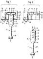
- the entire household appliance is composed of the basic appliance 1, one that can be connected to it Adapter body 2 and a power supply unit 3 designed as a wall bracket, the power supply unit 3 being electrically connected to the adapter body 2 by the cable 4 and via this to the base unit.
- the basic device 1 is removed from the adapter body 2 in a manner described later, the latter remaining in the wall bracket 3.
- FIG 3 shows the mode of operation of the hand mixer 1 as a power supply unit, the basic unit 1 remaining connected to the adapter body 2. Both devices 1, 2 are taken together from the wall holder and the basic device 1 is fed via the cable 4 through the electrical supply network (not shown).
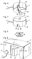
- FIG. 4 shows the basic device 1, which - as can also be seen in FIG. 10 - contains an electric motor 5, an on / off switch 6, an accumulator 7 (only FIG. 10) and a switching device 8.
- the housing of the basic device 1 is formed according to FIG. 3 in a manner known per se as an essentially cylindrical body 34 with gradations 9, 35, 36, onto which a cylindrical shaft 27 with a bell formed at the end, which is open at the bottom, extends downward 28 connects.
- a working tool (knife) 30 which is drive-connected to the electric motor 5 via a drive shaft 29 centered in the shaft 27.
- the bell 28 has slots 31 running approximately horizontally on the circumference, which enable better circulation of the food when mixing or chopping.
- the on / off switch 6 is diametrically opposed to a recessed grip 9.
- a bar 10 is formed, which, arranged centrally, is diametrical extends over the entire diameter and its end face 32 is aligned with the lateral surface 33 of the base body 34.
- Both the on / off switch 6 and the release button 11 are aligned with one another and protrude equally from the lateral surface 33.
- a latching bolt 12 protrudes from the side walls 37 of the strip 10.
- the electrical contacts 13 of the three poles P, C and N are indicated on each of these side walls 37.
- the actuation button 14 protrudes in a ramp shape. It serves to actuate the switching device 8.
- the actuation button 14 according to FIG. 4 is automatically pressed downwards when the strip 10 is inserted into the corresponding groove 15 of the adapter body 2 shown in FIG. 6.
- the lateral boundary walls 39 of the groove 15 are each provided with recesses 16 according to FIG. 6, into which the locking bolts 12 of the basic device 1 can engage.
- the contacts 17 are formed on these walls 39, which are in electrical connection with one another after the locking of the basic device 1 and adapter body 2.
- the locking bolts 12 are under prestress of the spring 18 which acts on their respective bearing bolts 40 in the sense that their locking portions 43 move out of the bar 10 in the direction of arrow 41.
- the bearing bolts 40 are perpendicular to the insertion direction X (FIG. 4) of the basic device 1, or according to FIG. 5, that is to say seen from above into the interior of the adapter body 2, in front of the locking sections 43, so that they move over their during the insertion process Allow sloping sections 19 to move slightly inward into the strip 10 against the force of the spring 18.
- the locking latch 12 By shifting Y the release button 11, the locking latch 12 can be pivoted inwards into the interior 42 so that they are disengaged from the recesses 16 (FIG. 6) will.
- the conical region 20 of the unlocking button 11 engages the inclined surfaces 44 of the latching bolts 12 when pressed inward in the Y direction.
- the release button 11 After actuation, the release button 11 is reset to the outside by the spring 18 and the locking latch 12.
- the locking sections 43 also automatically come out of the side walls 37 of the openings 45 again.
- the circular disk-shaped adapter body 2 has a central wedge-shaped recess 21 on its end face 46 opposite the groove 15.
- the depression 21 serves for the engagement of a snap button 22, which is placed in the housing of the power supply unit 3 on the underside 47 of the recess 48.
- the recess 48 serves to receive the adapter body 2, as is clearly shown in FIGS. 1 and 2.
- the cable 4 is guided in the channel 50.
- the recess 48 is followed by the cylindrical receiving space 51, which serves to receive the body 34.
- 8 also shows the rotary knob 23 for speed control and a control lamp 24, which can be used, for example, to check the charge of the accumulator 7.
- the power supply unit 3 contains, in addition to the actual power supply unit 25, which converts the AC line voltage into a substantially lower DC voltage, a speed control 26 and a circuit 56, which also makes the power supply unit 3 operable as a charger.
- the circuit 56 contains a current limit and a discharge protection diode for the accumulator. The latter two elements are short-circuited by a magnetically actuated microswitch (not shown) when the hand mixer 1 is operating on a rechargeable battery. When the microswitch is open, i.e. when the hand mixer 1 is operated as a power supply, the accumulator can also be charged when the device 1 is in operation.
- the electrical structure of the basic device 1 is to be explained in more detail below with reference to FIG. 10.
- the contact 13 - in FIG. 10 the contacts 13 are shown for better illustration instead of on the rare walls 37, 39 on the end faces 36, 52, that is to say in a horizontal plane, which is also conceivable - is for connection to the 3- 3-core cable 4 formed with the individual contacts P, C and N.
- the contact N is connected directly to the electric motor 5 via the line 53, the contact P with the interposition of the on / off switch 6 via the line 54.
- N stands for negative, P for positive and C for loading.
- the negative pole of the accumulator 7 is connected to the line 53 from the contact N to the electric motor 5.
- the positive pole of the accumulator 7 is connected to the line 54 between the contact P and the on / off switch 6 when the actuation button 14 is not actuated.
- the switching device 8 switches the positive pole of the accumulator 7 in connection with the contact C, so that the accumulator 7 is charged is possible.
- the basic device 1 is removed by actuating the unlocking button 11, the adapter body 2, as shown in FIG. 2, remains in the housing of the power supply unit 3 due to the action of the snap button 22.
- the actuating button 14 jumps up due to its bias by a spring, not shown, and brings the switching device 8 into the position shown in Fig. 10, so that the battery 7 is connected to the on / off switch 6.
- the accumulator 7 remains by the actuating button 14 or by the switching device 8 separated from the on / off switch 6 and the accumulator 7 is connected to the charging line C by the switching device 8. Since the contacts 13 and 17 are connected to one another in this state, the accumulator can be charged on the one hand; on the other hand, mains operation of the basic device 1 is now possible, so that the operating speed can be varied via the speed control 26 by means of the rotary knob 23 if required.
- the electrical changeover within the basic device 1 takes place automatically by connecting or disconnecting the same to the adapter body 2. In this way, incorrect operation is not possible. Especially since the actuation button 14 is not accessible from the outside during mains operation. While the stick mixer is operating, only the device can be switched off by accidentally pressing the actuation button 14.
Landscapes
- Engineering & Computer Science (AREA)
- Food Science & Technology (AREA)
- Power Engineering (AREA)
- Mechanical Engineering (AREA)
- Food-Manufacturing Devices (AREA)
- General Preparation And Processing Of Foods (AREA)
Applications Claiming Priority (2)
| Application Number | Priority Date | Filing Date | Title |
|---|---|---|---|
| DE4220233 | 1992-06-20 | ||
| DE4220233A DE4220233A1 (de) | 1992-06-20 | 1992-06-20 | Haushaltsgerät zum Bearbeiten von Lebensmitteln |
Publications (2)
| Publication Number | Publication Date |
|---|---|
| EP0575723A1 true EP0575723A1 (fr) | 1993-12-29 |
| EP0575723B1 EP0575723B1 (fr) | 1996-08-21 |
Family
ID=6461455
Family Applications (1)
| Application Number | Title | Priority Date | Filing Date |
|---|---|---|---|
| EP93106428A Expired - Lifetime EP0575723B1 (fr) | 1992-06-20 | 1993-04-21 | Appareil ménager à traiter des aliments |
Country Status (5)
| Country | Link |
|---|---|
| US (1) | US5489807A (fr) |
| EP (1) | EP0575723B1 (fr) |
| AT (1) | ATE141474T1 (fr) |
| DE (2) | DE4220233A1 (fr) |
| ES (1) | ES2090760T3 (fr) |
Cited By (2)
| Publication number | Priority date | Publication date | Assignee | Title |
|---|---|---|---|---|
| US5489807A (en) * | 1992-06-20 | 1996-02-06 | Braun Aktiengesellschaft | Domestic appliance for processing foods |
| EP2015389A1 (fr) * | 2007-07-04 | 2009-01-14 | Braun GmbH | Dispositif doté d'un appareil électrique et d'une station de charge |
Families Citing this family (11)
| Publication number | Priority date | Publication date | Assignee | Title |
|---|---|---|---|---|
| USD400166S (en) | 1997-07-29 | 1998-10-27 | Black & Decker Inc. | Charger housing |
| US6573621B2 (en) | 2000-12-01 | 2003-06-03 | S-B Power Tool Company | AC/DC power supply system for power tools |
| JP2006325395A (ja) * | 2005-05-17 | 2006-11-30 | Milwaukee Electric Tool Corp | 動力工具、バッテリ、充電器、およびそれらを動作させる方法 |
| DE102005038926A1 (de) * | 2005-08-17 | 2007-03-22 | BSH Bosch und Siemens Hausgeräte GmbH | Akkubetriebenes elektromotorisches Küchengerät |
| DE102005038919A1 (de) * | 2005-08-17 | 2007-03-15 | BSH Bosch und Siemens Hausgeräte GmbH | Elektromotorisches Küchengerät mit elektrischer oder elektronischer Verriegelung |
| DE102005038922A1 (de) * | 2005-08-17 | 2007-02-22 | BSH Bosch und Siemens Hausgeräte GmbH | Multifunktionaler Halter für einen Stabmixer |
| DE102005038923A1 (de) * | 2005-08-17 | 2007-02-22 | BSH Bosch und Siemens Hausgeräte GmbH | Ladesystem für ein akkubetriebenes Küchengerät |
| DE102009007359A1 (de) * | 2009-02-04 | 2010-08-05 | Zweibrüder Optoelectronics GmbH | Ladestation |
| US9915467B1 (en) | 2016-11-02 | 2018-03-13 | Sheila Mosley | Refrigerator with integrated multi-speed blender |
| DE102017112663A1 (de) * | 2017-06-08 | 2018-12-13 | Vorwerk & Co. Interholding Gmbh | Verfahren zum Betrieb eines einen Akkumulator aufweisenden Haushaltsgerätes |
| CA3121630A1 (fr) * | 2018-12-06 | 2020-06-11 | Columbia Insurance Company | Appareil d'appareil modulaire configure pour de multiples accessoires |
Citations (7)
| Publication number | Priority date | Publication date | Assignee | Title |
|---|---|---|---|---|
| DE1126082B (de) * | 1960-12-16 | 1962-03-22 | Dr Hermann Neuhierl | Kuechenmaschine |
| DE1221919B (de) * | 1960-01-11 | 1966-07-28 | Sperry Rand Corp | Elektrisches Rasiergeraet fuer Batteriebetrieb |
| DE1248875B (de) * | 1967-08-31 | ESGE Export A G Glarus (Schweiz) | Netzunabhangiges, elektromotorisch angetne benes Handmischgerat | |
| FR1554399A (fr) * | 1967-02-17 | 1969-01-17 | ||
| US3525912A (en) * | 1966-03-28 | 1970-08-25 | Scovill Manufacturing Co | Selectable power source for a motor driven appliance |
| US3710224A (en) * | 1970-12-31 | 1973-01-09 | Sperry Rand Corp | Display stand for rechargeable battery operated appliance |
| EP0341395A1 (fr) * | 1988-05-11 | 1989-11-15 | Wella Aktiengesellschaft | Dispositif pour un appareil électrique |
Family Cites Families (4)
| Publication number | Priority date | Publication date | Assignee | Title |
|---|---|---|---|---|
| US4413211A (en) * | 1981-12-23 | 1983-11-01 | Fowler Ricky C | Control circuit for electrical appliances |
| FR2582162B1 (fr) * | 1985-05-14 | 1987-08-14 | Black & Decker Inc | Dispositif pour la charge d'ensembles accumulateurs electriques |
| US4620110A (en) * | 1985-07-15 | 1986-10-28 | General Electric Company | Compact power supply module and cord |
| DE4220233A1 (de) * | 1992-06-20 | 1993-12-23 | Braun Ag | Haushaltsgerät zum Bearbeiten von Lebensmitteln |
-
1992
- 1992-06-20 DE DE4220233A patent/DE4220233A1/de not_active Withdrawn
-
1993
- 1993-04-21 DE DE59303480T patent/DE59303480D1/de not_active Expired - Lifetime
- 1993-04-21 AT AT93106428T patent/ATE141474T1/de active
- 1993-04-21 EP EP93106428A patent/EP0575723B1/fr not_active Expired - Lifetime
- 1993-04-21 ES ES93106428T patent/ES2090760T3/es not_active Expired - Lifetime
- 1993-06-07 US US08/073,126 patent/US5489807A/en not_active Expired - Fee Related
Patent Citations (7)
| Publication number | Priority date | Publication date | Assignee | Title |
|---|---|---|---|---|
| DE1248875B (de) * | 1967-08-31 | ESGE Export A G Glarus (Schweiz) | Netzunabhangiges, elektromotorisch angetne benes Handmischgerat | |
| DE1221919B (de) * | 1960-01-11 | 1966-07-28 | Sperry Rand Corp | Elektrisches Rasiergeraet fuer Batteriebetrieb |
| DE1126082B (de) * | 1960-12-16 | 1962-03-22 | Dr Hermann Neuhierl | Kuechenmaschine |
| US3525912A (en) * | 1966-03-28 | 1970-08-25 | Scovill Manufacturing Co | Selectable power source for a motor driven appliance |
| FR1554399A (fr) * | 1967-02-17 | 1969-01-17 | ||
| US3710224A (en) * | 1970-12-31 | 1973-01-09 | Sperry Rand Corp | Display stand for rechargeable battery operated appliance |
| EP0341395A1 (fr) * | 1988-05-11 | 1989-11-15 | Wella Aktiengesellschaft | Dispositif pour un appareil électrique |
Cited By (2)
| Publication number | Priority date | Publication date | Assignee | Title |
|---|---|---|---|---|
| US5489807A (en) * | 1992-06-20 | 1996-02-06 | Braun Aktiengesellschaft | Domestic appliance for processing foods |
| EP2015389A1 (fr) * | 2007-07-04 | 2009-01-14 | Braun GmbH | Dispositif doté d'un appareil électrique et d'une station de charge |
Also Published As
| Publication number | Publication date |
|---|---|
| EP0575723B1 (fr) | 1996-08-21 |
| ATE141474T1 (de) | 1996-09-15 |
| DE4220233A1 (de) | 1993-12-23 |
| ES2090760T3 (es) | 1996-10-16 |
| DE59303480D1 (de) | 1996-09-26 |
| US5489807A (en) | 1996-02-06 |
Similar Documents
| Publication | Publication Date | Title |
|---|---|---|
| EP0575723B1 (fr) | Appareil ménager à traiter des aliments | |
| DE60003499T2 (de) | Lösbare Verbindung zwischen Batteriemodulen und elektrischen Geräten | |
| EP0485784B1 (fr) | Chargeur pour batteries rechargeables | |
| EP0499840B1 (fr) | Appareil électrique | |
| DE602004013398T2 (de) | batterieauswurfsmechanismus | |
| EP0374600B1 (fr) | Dispositif d'alimentation en courant | |
| EP0341395A1 (fr) | Dispositif pour un appareil électrique | |
| DE3422364A1 (de) | Batteriebetriebenes elektrisches geraet | |
| EP1670619A1 (fr) | Visseuse a batterie | |
| WO2005039829A1 (fr) | Visseuse a batterie | |
| DE102020200317A1 (de) | Akkupack für eine Handwerkzeugmaschine, Handwerkzeugmaschine und Ladegerät | |
| EP0499839B1 (fr) | Appareil électrique | |
| EP3367464B1 (fr) | Module d'accumulateur d'énergie et appareil éléctrique | |
| EP0499838B1 (fr) | Appareil électrique | |
| EP4050716A2 (fr) | Porte-élément et bloc-accumulateur doté d'un porte-élément | |
| DE8505814U1 (de) | Elektrowerkzeug | |
| DE4142159C2 (de) | Haltevorrichtung für batteriebetriebene Elektrogeräte mit einer Anschlußkupplung an eine Stromquelle | |
| DE202015105602U1 (de) | Handwerkzeugmaschine | |
| DE3742240A1 (de) | Elektrisches handwerkzeug mit einem akkuteil | |
| DE9313032U1 (de) | Mobiles Arbeitsgerät | |
| DE1221919B (de) | Elektrisches Rasiergeraet fuer Batteriebetrieb | |
| DE102020214780A1 (de) | Energieversorgungsgerät für ein akkubetriebenes Elektrogerät oder einen Wechselakkupack-Adapter sowie System bestehend aus zumindest einem akkubetriebenen Elektrogerät und/oder einem Wechselakkupack-Adapter sowie einem Energieversorgungsgerät | |
| CH229736A (de) | Aus einer Akkumulatortaschenlampe und einem hierzu passenden Netzanschluss-Ladegerät bestehende Kombination. | |
| CH628860A5 (en) | Power supply device for electrical garden appliances | |
| DE3876367T2 (de) | Elektrischer rasierer. |
Legal Events
| Date | Code | Title | Description |
|---|---|---|---|
| PUAI | Public reference made under article 153(3) epc to a published international application that has entered the european phase |
Free format text: ORIGINAL CODE: 0009012 |
|
| AK | Designated contracting states |
Kind code of ref document: A1 Designated state(s): AT CH DE ES FR GB LI |
|
| 17P | Request for examination filed |
Effective date: 19940128 |
|
| 17Q | First examination report despatched |
Effective date: 19950303 |
|
| RAP1 | Party data changed (applicant data changed or rights of an application transferred) |
Owner name: BRAUN AKTIENGESELLSCHAFT |
|
| GRAH | Despatch of communication of intention to grant a patent |
Free format text: ORIGINAL CODE: EPIDOS IGRA |
|
| GRAA | (expected) grant |
Free format text: ORIGINAL CODE: 0009210 |
|
| GRAH | Despatch of communication of intention to grant a patent |
Free format text: ORIGINAL CODE: EPIDOS IGRA |
|
| AK | Designated contracting states |
Kind code of ref document: B1 Designated state(s): AT CH DE ES FR GB LI |
|
| REF | Corresponds to: |
Ref document number: 141474 Country of ref document: AT Date of ref document: 19960915 Kind code of ref document: T |
|
| REG | Reference to a national code |
Ref country code: CH Ref legal event code: NV Representative=s name: PATENTANWALTSBUREAU BOSSHARD UND LUCHS |
|
| REF | Corresponds to: |
Ref document number: 59303480 Country of ref document: DE Date of ref document: 19960926 |
|
| GBT | Gb: translation of ep patent filed (gb section 77(6)(a)/1977) |
Effective date: 19960906 |
|
| REG | Reference to a national code |
Ref country code: ES Ref legal event code: FG2A Ref document number: 2090760 Country of ref document: ES Kind code of ref document: T3 |
|
| ET | Fr: translation filed | ||
| ET | Fr: translation filed | ||
| REG | Reference to a national code |
Ref country code: ES Ref legal event code: FG2A Ref document number: 2090760 Country of ref document: ES Kind code of ref document: T3 |
|
| PLBE | No opposition filed within time limit |
Free format text: ORIGINAL CODE: 0009261 |
|
| 26N | No opposition filed | ||
| PGFP | Annual fee paid to national office [announced via postgrant information from national office to epo] |
Ref country code: AT Payment date: 19990426 Year of fee payment: 7 |
|
| PGFP | Annual fee paid to national office [announced via postgrant information from national office to epo] |
Ref country code: CH Payment date: 19990507 Year of fee payment: 7 |
|
| PGFP | Annual fee paid to national office [announced via postgrant information from national office to epo] |
Ref country code: GB Payment date: 20000323 Year of fee payment: 8 |
|
| PGFP | Annual fee paid to national office [announced via postgrant information from national office to epo] |
Ref country code: ES Payment date: 20000405 Year of fee payment: 8 |
|
| PGFP | Annual fee paid to national office [announced via postgrant information from national office to epo] |
Ref country code: FR Payment date: 20000417 Year of fee payment: 8 |
|
| PG25 | Lapsed in a contracting state [announced via postgrant information from national office to epo] |
Ref country code: AT Free format text: LAPSE BECAUSE OF NON-PAYMENT OF DUE FEES Effective date: 20000421 |
|
| REG | Reference to a national code |
Ref country code: FR Ref legal event code: CD Ref country code: FR Ref legal event code: CA |
|
| PG25 | Lapsed in a contracting state [announced via postgrant information from national office to epo] |
Ref country code: LI Free format text: LAPSE BECAUSE OF NON-PAYMENT OF DUE FEES Effective date: 20000430 Ref country code: CH Free format text: LAPSE BECAUSE OF NON-PAYMENT OF DUE FEES Effective date: 20000430 |
|
| REG | Reference to a national code |
Ref country code: CH Ref legal event code: PFA Free format text: BRAUN AKTIENGESELLSCHAFT TRANSFER- BRAUN AKTIENGESELLSCHAFT;BRAUN GMBH Ref country code: CH Ref legal event code: NV Representative=s name: PATENTANWALTSBUREAU BOSSHARD UND LUCHS;LUCHS & PAR |
|
| REG | Reference to a national code |
Ref country code: CH Ref legal event code: PL |
|
| REG | Reference to a national code |
Ref country code: ES Ref legal event code: PC2A |
|
| PG25 | Lapsed in a contracting state [announced via postgrant information from national office to epo] |
Ref country code: GB Free format text: LAPSE BECAUSE OF NON-PAYMENT OF DUE FEES Effective date: 20010421 |
|
| PG25 | Lapsed in a contracting state [announced via postgrant information from national office to epo] |
Ref country code: ES Free format text: LAPSE BECAUSE OF NON-PAYMENT OF DUE FEES Effective date: 20010423 |
|
| PG25 | Lapsed in a contracting state [announced via postgrant information from national office to epo] |
Ref country code: FR Free format text: THE PATENT HAS BEEN ANNULLED BY A DECISION OF A NATIONAL AUTHORITY Effective date: 20010430 |
|
| GBPC | Gb: european patent ceased through non-payment of renewal fee |
Effective date: 20010421 |
|
| REG | Reference to a national code |
Ref country code: FR Ref legal event code: ST |
|
| PGFP | Annual fee paid to national office [announced via postgrant information from national office to epo] |
Ref country code: DE Payment date: 20020412 Year of fee payment: 10 |
|
| REG | Reference to a national code |
Ref country code: ES Ref legal event code: FD2A Effective date: 20030203 |
|
| PG25 | Lapsed in a contracting state [announced via postgrant information from national office to epo] |
Ref country code: DE Free format text: LAPSE BECAUSE OF THE APPLICANT RENOUNCES Effective date: 20030405 |