EP0575980A1 - Polarisierte elektromagnetische Betätigungsvorrichtung - Google Patents
Polarisierte elektromagnetische Betätigungsvorrichtung Download PDFInfo
- Publication number
- EP0575980A1 EP0575980A1 EP93110018A EP93110018A EP0575980A1 EP 0575980 A1 EP0575980 A1 EP 0575980A1 EP 93110018 A EP93110018 A EP 93110018A EP 93110018 A EP93110018 A EP 93110018A EP 0575980 A1 EP0575980 A1 EP 0575980A1
- Authority
- EP
- European Patent Office
- Prior art keywords
- dome
- coil
- keeper
- compartment
- shaped
- Prior art date
- Legal status (The legal status is an assumption and is not a legal conclusion. Google has not performed a legal analysis and makes no representation as to the accuracy of the status listed.)
- Withdrawn
Links
- 230000005291 magnetic effect Effects 0.000 claims abstract description 11
- 238000003780 insertion Methods 0.000 claims abstract description 3
- 230000037431 insertion Effects 0.000 claims abstract description 3
- 230000014759 maintenance of location Effects 0.000 claims description 4
- 230000007246 mechanism Effects 0.000 claims description 4
- 239000000463 material Substances 0.000 claims description 3
- 230000004308 accommodation Effects 0.000 claims description 2
- 230000009471 action Effects 0.000 claims description 2
- 229920002457 flexible plastic Polymers 0.000 claims description 2
- 239000007787 solid Substances 0.000 claims description 2
- 230000001788 irregular Effects 0.000 claims 1
- RYGMFSIKBFXOCR-UHFFFAOYSA-N Copper Chemical compound [Cu] RYGMFSIKBFXOCR-UHFFFAOYSA-N 0.000 description 4
- 230000008878 coupling Effects 0.000 description 4
- 238000010168 coupling process Methods 0.000 description 4
- 238000005859 coupling reaction Methods 0.000 description 4
- 238000004873 anchoring Methods 0.000 description 2
- 239000003302 ferromagnetic material Substances 0.000 description 2
- 238000004519 manufacturing process Methods 0.000 description 2
- 230000004048 modification Effects 0.000 description 2
- 238000012986 modification Methods 0.000 description 2
- 239000000428 dust Substances 0.000 description 1
- 230000005294 ferromagnetic effect Effects 0.000 description 1
- 239000012535 impurity Substances 0.000 description 1
- 230000008595 infiltration Effects 0.000 description 1
- 238000001764 infiltration Methods 0.000 description 1
- 238000009413 insulation Methods 0.000 description 1
- 230000000670 limiting effect Effects 0.000 description 1
- 239000002245 particle Substances 0.000 description 1
- 230000002093 peripheral effect Effects 0.000 description 1
- 229920003023 plastic Polymers 0.000 description 1
- 239000004033 plastic Substances 0.000 description 1
- 230000001681 protective effect Effects 0.000 description 1
Images

Classifications
-
- H—ELECTRICITY
- H01—ELECTRIC ELEMENTS
- H01H—ELECTRIC SWITCHES; RELAYS; SELECTORS; EMERGENCY PROTECTIVE DEVICES
- H01H71/00—Details of the protective switches or relays covered by groups H01H73/00 - H01H83/00
- H01H71/10—Operating or release mechanisms
- H01H71/12—Automatic release mechanisms with or without manual release
- H01H71/24—Electromagnetic mechanisms
- H01H71/32—Electromagnetic mechanisms having permanently magnetised part
- H01H71/325—Housings, assembly or disposition of different elements in the housing
-
- H—ELECTRICITY
- H01—ELECTRIC ELEMENTS
- H01H—ELECTRIC SWITCHES; RELAYS; SELECTORS; EMERGENCY PROTECTIVE DEVICES
- H01H71/00—Details of the protective switches or relays covered by groups H01H73/00 - H01H83/00
- H01H71/02—Housings; Casings; Bases; Mountings
- H01H71/0207—Mounting or assembling the different parts of the circuit breaker
- H01H2071/0242—Assembling parts of a circuit breaker by using snap mounting techniques
Definitions
- the present invention relates to a polarized electromagnetic actuator improved from the point of view of both structure and mutual assembly of its various components.
- electromagnet actuators are devices activated by electrical signals of extremely low power, which can actuate mechanisms which use or include much higher power (for example to cause the opening of electrical circuits of high-power equipment) only when said actuation is required.
- Current polarized electromagnetic actuators generally comprise a box-like body which includes a fixed ferromagnetic core inserted in a coil of insulated copper wire and supplied with direct or even alternating current; a movable keeper, contrasted by return springs, cooperates with said core.
- a permanent magnet is arranged in contact with said fixed core, polarizes the magnetic circuit and retains the keeper in contact with the fixed core until the coil is fed so as to create a polarity which is opposite to the polarity of the permanent magnet. At this point the keeper releases the fixed core by virtue of the contrasting action of the return spring.
- the actuator disclosed and claimed in said utility model is substantially constituted by a prism-shaped body provided with through cavities, i.e. cavities which are open at their opposite ends, in one of which an arm of a U-shaped core, made of ferromagnetic material, is inserted; the other arm of said core is axially inserted in a coil accommodated in a second cavity of said prism-shaped body.
- a permanent magnet is inserted in the cavity formed between said first and second cavities and is placed in contact with the base of said U-shaped core.
- a metallic keeper is pivoted above said body and is contrasted by a spring for returning it to the open position accommodated in an additional cavity of said prism-shaped body.
- Said prism-shaped body which accommodates the coil, the core and the moving keeper, is sealed and closed at the bottom by a baseplate and is sealed and closed at the top by a dome enclosing said moving keeper and is provided with a hole for the passage of a pivot which is placed in contact with the keeper and is intended to actuate a kinematic system which operates at high power.
- Said actuator furthermore has means for oscillatably engaging the keeper on the fixed core, fixed studs on the bottom of the prism-shaped body for the stable anchoring of the baseplate and other parts for retaining the coil and other components in a stable position.
- said actuator has a structure which is simpler and easier to assemble than that of prior actuators, it has proved itself to be susceptible to further modifications and improvements aimed at simplifying its structure and at improving, in economical terms as well, the production process and its reliability in the course of time.
- the aim of the present invention is to provide an improved polarized electromagnetic actuator which eliminates the drawbacks and limitations of known actuators and above all, to entail further rationalization of the operations for mutually coupling the various components and to simplify and facilitate the steps for the assembly of said components, both manually and by means of automatic assembly equipment, with the result of significantly improving the entire production process.
- An object of the present invention is to provide an electromagnetic actuator designed so that it is substantially sealed against infiltration, in the various cavities, of dust and particles which may have detached from the coil and/or from the permanent magnet, with evident advantages as regards the correct operation of the unit and most of all with the assurance of perfect contact between the keeper and the fixed core.
- a polarized electromagnetic actuator of the type which comprises a prism-shaped supporting body having separate compartments with through cavities for containing a substantially U-shaped core, a coil of conducting wire, a polarizing permanent magnet and a moving keeper contrasted by a return spring, which actuates an actuation pin of an external mechanism, and a dome-shaped lid and a lower closure baseplate; said actuator being constituted, according to the present invention, by a prism-shaped main body internally provided with: a first compartment, suitable to contain said axially hollow coil of conducting wire; a second compartment for containing said permanent magnet; two further separate compartments, one of which is tubular and axially formed in a central position with respect to said first compartment for the insulated accommodation of an arm of said U-shaped core, the other compartment being provided to accommodate the second arm of said core; and a further cavity for accommodating said keeper return spring; said first and second compartments being closed upwardly so as to allow insertion
- said means for the removable engagement of the dome to the main body are constituted by two flat tabs rigidly coupled to said dome, made of flexible plastic material and provided with holes or openings; said tabs, by entering two guides formed on the internal wall of the main body, are suitable to stably engage their holes on teeth or protrusions which protrude from said guides arranged inside the main body.
- each one of said tabs engaging the main body can disengage from said body by using a rod or the like, which is insertable in a hole formed in the wall of said body and can be pushed against the solid part of said tabs until the holes of said tabs disengage from the retention teeth, thus allowing to remove the dome.
- said closure baseplate is provided with means for its snap-together engagement with the main body; said means are constituted by flexible studs, shaped like a hook or the like, which can engage in a snap-together manner within holes defined in the wall of said body in order to keep the permanent magnet, the coil and the core which constitutes the magnetic circuit stably in position.
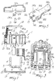
- the actuator comprises a main body 1 substantially shaped like a parallelepiped; lug-shaped means or the like (not shown) are rigidly coupled to the outer peripheral region of said main body to fix said body 1 to the external mechanism which the actuator must actuate.
- cavities or compartments are formed inside the body 1, and have mutually parallel axes and different dimensions; more precisely, the cavities 2 and 2a are meant to accommodate respectively the arm 3 and the arm 4 of a core 5 made of ferromagnetic material, which is substantially shaped like an uppercase letter U and is provided, in the substantially straight portion 5a, with through holes 6 the purpose whereof will become apparent hereinafter; the cavity 7, which is coaxial to the cavity 2, is meant to accommodate the coil of conducting wire 8, which is axially hollow, so that when it is inserted in the cavity 7 it is guided, so as to be insulated, on the hollow body which forms the cavity 2 within which the arm 3 of the core 5 is inserted.
- a permanent magnet 10 is inserted in the cavity 9, whereas the cavity 11 accommodates a return spring 12; one end of said spring is anchored to a pin or hook 12a, and its opposite end 12b is anchored within a hole 13 formed at the end of a moving keeper 14; said keeper has, at the end opposite to the one where it couples to the spring, a flat portion 14a which is meant to be moved into contact with the upper end of the arm 3 of the core 5.
- the cavity 7 of the coil and the cavity 9 of the magnet are closed upwardly (the side of the keeper) so as to constitute blind compartments capable of stably accommodating the coil and the magnet without requiring elastic retention means.
- said cavity 7 accommodates a coil 8 constituted by insulated copper wire of the self-cementing type, i.e. which maintains its shape since the insulation which encloses the copper wire, when heated, welds to the adjacent turns.
- the coil 8 is thus constituted exclusively by the insulated copper wire, which is inserted astride the insulating compartment 2. In this manner there is no connection between the cavities 7 and 9 and the moving keeper 14 on the side where said keeper will be engaged by the fixed magnetic circuit 5, and thus any impurities which might detach from the magnet 10 and from the coil 8 could not penetrate between the keeper 14 and the magnetic circuit 5.
- Said moving keeper is furthermore monolithically provided with two opposite pairs of lateral wings 14b and 14c which form the pivoting region. More in detail, the recesses comprised between said pairs of lateral wings of the keeper engage shaped teeth 15 formed correspondingly on the main body 1, so that the wings 14b and 14c in practice oscillate on the shaped teeth 15 under the traction applied by the spring 12, which has an axis inclined so as to provide a horizontal component of the force which causes the keeper to adhere to the shaped teeth 15.
- the body 1 furthermore has, in its lower part, fixed studs 16 which allow coupling to a baseplate 17 which can be anchored to the body 1 by virtue of the snap-acting means described hereafter.
- Said baseplate 17, which must close all of the lower part of the main body 1, once the magnet 10, the coil 8 and the fixed magnetic circuit 5 have been positioned, engages the main body 1 on one side through two tabs 18 which enter two cavities 19 of the body 1 from the other side by means of two snap-acting tabs 20 formed by the baseplate 17, the teeth whereof enter the two cavities 21 formed in the main body 1 (figures 2, 3 and 4).
- the fixed magnetic circuit 5 is inserted so that its holes 6 are crossed by the studs 16 formed in the body 1 and protruding therefrom.
- the baseplate 17 also fits its holes 17a over said studs 16. Said studs, when the baseplate is closed, protrude by a very small extent from the outer plane of the baseplate in order to be subsequently hot-riveted, as will become apparent hereinafter.
- the actuator is then closed upwardly by a dome 22 which is centrally provided with a hole 22a for the passage of a conventional actuation pin 23.
- Said upper dome 22 after the pin 23 has been accommodated therein, closes onto the main body 1 by means of two tabs 24 which enter the compartments 25 until the rectangular holes 24a of the tabs 24 elastically engage the protrusions 25a, locking themselves in this position. Since the compartments 25 are inside the body 1, it is no longer possible to remove the dome 22.
- said figure illustrates an arrangement of the components of the actuator which can be used both for manual and automatic assembly.
- This arrangement is non-limitative, in that any other initial arrangement can be assumed, so long as it achieves the same final result.
- the main body 1 is held still and in inverted position by a fixture of any kind, and then the magnet 10 and the coil 8 are loaded first with a downward movement.
- This is followed by the assembly of the fixed magnetic circuit 5.
- a thin rectangular plate 27 is inserted from below in the two shaped teeth 15; said plate is provided with two holes at the teeth, is made of a suitable material, even plastics, and has the purpose of reducing the friction coefficient in the mutual movement between the keeper 14 and the fixed magnetic circuit 5 in addition to constituting, according to the requirements, a gap of said magnetic circuit.
- the eyelet of the spring 12 is then pulled through the compartment 11 until it engages the transverse bar 21.
- the other eyelet of the spring 12 has already been engaged in the hole 13 of the keeper 14, the two recesses 14e whereof fit between the shaped teeth 15.
- the dome 22, in the hole 22a whereof the actuation pin 23 has already been inserted is inserted until the tabs 24, inserted in the compartments 25 of the main body 1, reach and pass beyond the two retention teeth 25a, anchoring themselves to said teeth.
Landscapes
- Physics & Mathematics (AREA)
- Electromagnetism (AREA)
- Electromagnets (AREA)
- Reciprocating, Oscillating Or Vibrating Motors (AREA)
Applications Claiming Priority (2)
| Application Number | Priority Date | Filing Date | Title |
|---|---|---|---|
| IT000636 IT226720Z2 (it) | 1992-06-25 | 1992-06-25 | Dispositivo attuatore elettromagnetico polarizzato |
| ITMI920636U | 1992-06-25 |
Publications (1)
| Publication Number | Publication Date |
|---|---|
| EP0575980A1 true EP0575980A1 (de) | 1993-12-29 |
Family
ID=11362497
Family Applications (1)
| Application Number | Title | Priority Date | Filing Date |
|---|---|---|---|
| EP93110018A Withdrawn EP0575980A1 (de) | 1992-06-25 | 1993-06-23 | Polarisierte elektromagnetische Betätigungsvorrichtung |
Country Status (2)
| Country | Link |
|---|---|
| EP (1) | EP0575980A1 (de) |
| IT (1) | IT226720Z2 (de) |
Cited By (1)
| Publication number | Priority date | Publication date | Assignee | Title |
|---|---|---|---|---|
| EA009364B1 (ru) * | 2004-10-21 | 2007-12-28 | Шнейдер Электрик Эндюстри Сас | Электромагнитное отключающее устройство и аппарат электрической защиты, содержащий подобное устройство |
Citations (5)
| Publication number | Priority date | Publication date | Assignee | Title |
|---|---|---|---|---|
| AT307558B (de) * | 1969-04-25 | 1973-05-25 | Siemens Ag | Bistabil betätigbares Relais |
| US3833869A (en) * | 1973-11-09 | 1974-09-03 | Amp Inc | Electromechanical relay |
| EP0332181A2 (de) * | 1988-03-09 | 1989-09-13 | OMRON Corporation | Elektromagnetische Vorrichtung |
| EP0337900A1 (de) * | 1988-04-14 | 1989-10-18 | Merlin Gerin | Elektromagnetischer Auslöser mit hoher Empfindlichkeit |
| EP0463884A2 (de) * | 1990-06-29 | 1992-01-02 | Takamisawa Electric Co., Ltd. | Elektromagnetisches Kleinrelais |
-
1992
- 1992-06-25 IT IT000636 patent/IT226720Z2/it active IP Right Grant
-
1993
- 1993-06-23 EP EP93110018A patent/EP0575980A1/de not_active Withdrawn
Patent Citations (5)
| Publication number | Priority date | Publication date | Assignee | Title |
|---|---|---|---|---|
| AT307558B (de) * | 1969-04-25 | 1973-05-25 | Siemens Ag | Bistabil betätigbares Relais |
| US3833869A (en) * | 1973-11-09 | 1974-09-03 | Amp Inc | Electromechanical relay |
| EP0332181A2 (de) * | 1988-03-09 | 1989-09-13 | OMRON Corporation | Elektromagnetische Vorrichtung |
| EP0337900A1 (de) * | 1988-04-14 | 1989-10-18 | Merlin Gerin | Elektromagnetischer Auslöser mit hoher Empfindlichkeit |
| EP0463884A2 (de) * | 1990-06-29 | 1992-01-02 | Takamisawa Electric Co., Ltd. | Elektromagnetisches Kleinrelais |
Cited By (1)
| Publication number | Priority date | Publication date | Assignee | Title |
|---|---|---|---|---|
| EA009364B1 (ru) * | 2004-10-21 | 2007-12-28 | Шнейдер Электрик Эндюстри Сас | Электромагнитное отключающее устройство и аппарат электрической защиты, содержащий подобное устройство |
Also Published As
| Publication number | Publication date |
|---|---|
| ITMI920636V0 (it) | 1992-06-25 |
| ITMI920636U1 (it) | 1993-12-25 |
| IT226720Z2 (it) | 1997-07-01 |
Similar Documents
| Publication | Publication Date | Title |
|---|---|---|
| EP2673793B1 (de) | Bistabiles elektromagnetisches relais mit einem x-drive-motor | |
| US4599597A (en) | Circuit protection devices | |
| US4760364A (en) | Electromagnetic contactor having improved structure and assembly | |
| CN102159758A (zh) | 用于家用电器,优选是洗衣机的门的安全锁 | |
| CA2029196C (en) | Slide switch | |
| JPS631694B2 (de) | ||
| US20120056701A1 (en) | Electromagnetic contact device | |
| US20150354248A1 (en) | Magnetically activated door-lock device | |
| CA1060928A (en) | Electrical contactor | |
| JPH07120496B2 (ja) | 電磁接触器 | |
| EP0051255A1 (de) | Elektromagnetisches Gerät | |
| JP2589610Y2 (ja) | 電磁接触器の相互鎖錠装置 | |
| US2400344A (en) | Electromagnet | |
| US5109210A (en) | Thermal relay with remote controlled resetting and testing junctions | |
| US3453571A (en) | Electromagnetic relay with convertible switch contact modules | |
| DE3615651A1 (de) | Elektromagnetisches kleinstrelais | |
| EP0462841B1 (de) | Polarisiertes elektromagnetisches Relais schmaler Bauform | |
| JPH0433628Y2 (de) | ||
| IT8224581A1 (it) | Relé polarizzato | |
| RU216214U1 (ru) | Исполнительный механизм электромеханического замка | |
| EP0880158B1 (de) | Elektromagnetisches Relais mit einer bistabilen Drucktaste für Sicherheitsprüfung | |
| JP2584399B2 (ja) | 電磁継電器 | |
| JP3924941B2 (ja) | スイッチ装置 | |
| JPH0512949Y2 (de) | ||
| JPH0724768Y2 (ja) | 電磁継電器 |
Legal Events
| Date | Code | Title | Description |
|---|---|---|---|
| PUAI | Public reference made under article 153(3) epc to a published international application that has entered the european phase |
Free format text: ORIGINAL CODE: 0009012 |
|
| AK | Designated contracting states |
Kind code of ref document: A1 Designated state(s): AT DE ES FR |
|
| 17P | Request for examination filed |
Effective date: 19940615 |
|
| STAA | Information on the status of an ep patent application or granted ep patent |
Free format text: STATUS: THE APPLICATION HAS BEEN WITHDRAWN |
|
| 18W | Application withdrawn |
Withdrawal date: 19960620 |