EP0576005A2 - Shredding device for paper web used in the manufacture of cigarettes with filters - Google Patents
Shredding device for paper web used in the manufacture of cigarettes with filters Download PDFInfo
- Publication number
- EP0576005A2 EP0576005A2 EP93110112A EP93110112A EP0576005A2 EP 0576005 A2 EP0576005 A2 EP 0576005A2 EP 93110112 A EP93110112 A EP 93110112A EP 93110112 A EP93110112 A EP 93110112A EP 0576005 A2 EP0576005 A2 EP 0576005A2
- Authority
- EP
- European Patent Office
- Prior art keywords
- drum
- pair
- shredding
- peripheral surface
- paper web
- Prior art date
- Legal status (The legal status is an assumption and is not a legal conclusion. Google has not performed a legal analysis and makes no representation as to the accuracy of the status listed.)
- Granted
Links
- 235000019504 cigarettes Nutrition 0.000 title claims description 48
- 238000004519 manufacturing process Methods 0.000 title claims description 3
- 230000002093 peripheral effect Effects 0.000 claims abstract description 45
- 238000003825 pressing Methods 0.000 claims abstract description 9
- 230000008878 coupling Effects 0.000 claims description 6
- 238000010168 coupling process Methods 0.000 claims description 6
- 238000005859 coupling reaction Methods 0.000 claims description 6
- 239000011435 rock Substances 0.000 abstract description 3
- 238000005096 rolling process Methods 0.000 description 21
- 239000003292 glue Substances 0.000 description 13
- 230000007246 mechanism Effects 0.000 description 7
- 230000004048 modification Effects 0.000 description 7
- 238000012986 modification Methods 0.000 description 7
- 238000005520 cutting process Methods 0.000 description 6
- 238000012545 processing Methods 0.000 description 6
- 238000004026 adhesive bonding Methods 0.000 description 4
- 125000006850 spacer group Chemical group 0.000 description 4
- 238000012546 transfer Methods 0.000 description 4
- 230000006866 deterioration Effects 0.000 description 2
- 238000000034 method Methods 0.000 description 2
- 238000012856 packing Methods 0.000 description 2
- 230000000149 penetrating effect Effects 0.000 description 2
- 230000008569 process Effects 0.000 description 2
- 238000013459 approach Methods 0.000 description 1
- 230000005540 biological transmission Effects 0.000 description 1
- 230000008859 change Effects 0.000 description 1
- 230000006835 compression Effects 0.000 description 1
- 238000007906 compression Methods 0.000 description 1
- 230000007423 decrease Effects 0.000 description 1
- 230000003247 decreasing effect Effects 0.000 description 1
- 238000001035 drying Methods 0.000 description 1
- 230000000694 effects Effects 0.000 description 1
- 239000000945 filler Substances 0.000 description 1
- 230000002035 prolonged effect Effects 0.000 description 1
- 230000004044 response Effects 0.000 description 1
- 238000011144 upstream manufacturing Methods 0.000 description 1
Images



Classifications
-
- B—PERFORMING OPERATIONS; TRANSPORTING
- B26—HAND CUTTING TOOLS; CUTTING; SEVERING
- B26D—CUTTING; DETAILS COMMON TO MACHINES FOR PERFORATING, PUNCHING, CUTTING-OUT, STAMPING-OUT OR SEVERING
- B26D1/00—Cutting through work characterised by the nature or movement of the cutting member or particular materials not otherwise provided for; Apparatus or machines therefor; Cutting members therefor
- B26D1/56—Cutting through work characterised by the nature or movement of the cutting member or particular materials not otherwise provided for; Apparatus or machines therefor; Cutting members therefor involving a cutting member which travels with the work otherwise than in the direction of the cut, i.e. flying cutter
- B26D1/62—Cutting through work characterised by the nature or movement of the cutting member or particular materials not otherwise provided for; Apparatus or machines therefor; Cutting members therefor involving a cutting member which travels with the work otherwise than in the direction of the cut, i.e. flying cutter and is rotating about an axis parallel to the line of cut, e.g. mounted on a rotary cylinder
- B26D1/626—Cutting through work characterised by the nature or movement of the cutting member or particular materials not otherwise provided for; Apparatus or machines therefor; Cutting members therefor involving a cutting member which travels with the work otherwise than in the direction of the cut, i.e. flying cutter and is rotating about an axis parallel to the line of cut, e.g. mounted on a rotary cylinder for thin material, e.g. for sheets, strips or the like
-
- A—HUMAN NECESSITIES
- A24—TOBACCO; CIGARS; CIGARETTES; SIMULATED SMOKING DEVICES; SMOKERS' REQUISITES
- A24C—MACHINES FOR MAKING CIGARS OR CIGARETTES
- A24C5/00—Making cigarettes; Making tipping materials for, or attaching filters or mouthpieces to, cigars or cigarettes
- A24C5/47—Attaching filters or mouthpieces to cigars or cigarettes, e.g. inserting filters into cigarettes or their mouthpieces
- A24C5/471—Attaching filters or mouthpieces to cigars or cigarettes, e.g. inserting filters into cigarettes or their mouthpieces by means of a connecting band
- A24C5/473—Cutting the connecting band
Definitions
- the present invention relates to a shredding device which is incorporated in a filter attachment designed to connect cigarettes and filters and which shreds paper web to produce paper pieces used for connecting cigarettes and filters.
- This type of filter attachment is provided with a non-contact type shredding device which is disclosed in the publication of examined JP patent application No. S61- 54559.
- This publicly known shredding device includes a receiving drum and a bladed drum.
- the bladed drum has a plurality of shredding blades arranged equidistantly on its peripheral surface and a pair of free rollers installed on its both ends. These free rollers have larger diameters than that of the bladed drum and they rotate while being in contact with the receiving drum.
- the shredding blades of the bladed drum shred the paper web into paper pieces of a specified length without contacting the peripheral surface of the receiving drum.
- the shredding blades of the bladed drum do not collide with the receiving drum at the time of shredding the paper web, making it possible to prevent shredding noises caused by such a collision and also to prevent damage to the receiving drum or the shredding blades.
- the shredding performance heavily depends on the size of the gap between the shredding blades and the receiving drum when the shredding blades approach most closely to the peripheral surface of the receiving drum.
- both drum shafts of the receiving drum and the bladed drum are urged by pressing screws in the directions that cause them to press toward each other.
- the pair of free rollers of the bladed drum are pressed and urged against the receiving drum by a predetermined force, thereby maintaining the gap at a constant dimension.
- An object of the present invention is to provide a shredding device which is capable of maintaining paper web shredding performance for a long time and of ensuring prolonged service life thereof.
- the above-mentioned object is achieved by a shredding device according to the present invention.
- the shredding device comprises the first drum which is rotated and which has a peripheral surface for carrying a paper web as the drum rotates, and shredding means for shredding the paper web into paper pieces of a specified length, in cooperation with the first drum, the shredding means including a second drum which is arranged close to and in parallel to the first drum and which is rotated in the opposite direction from the first drum, a pair of free rollers which are installed at both sides of the second drum coaxially with the second drum and which have a larger outside diameter than the second drum and rotate while contacting the peripheral surface of the first drum, a plurality of shredding blades which are provided circumferentially on the peripheral surface of the second drum at equal intervals and which pass the first drum with a predetermined gap between themselves and the peripheral surface of the first drum as the second drum is rotated, the shredding blades shredding the paper web on the first drum while passing, supporting means for supporting the
- the second drum and the pair of free rollers are supported by the supporting means so that they are allowed to move toward or away from the peripheral surface of the first drum and are constantly urged toward the peripheral surface of the first drum by the urging means. Accordingly, since the pair of free rollers having a larger outside diameter than the second drum rotate while being in contact with the peripheral surface of the first drum, the second drum rotates without causing the shredding blades to contact the peripheral surface of the first drum.
- a paper web is supplied between the first drum and the second drum which are rotated in the opposite directions from each other.
- the paper web passes through the drums, the paper web is cut into individual paper pieces by the shredding blades of the second drum.
- the shredding blades of the second drum do not collide the peripheral surface of the first drum. As a result, it is possible to prevent the cutting noise and damage to the peripheral surface of the first drum and the shredding blades at the time of shredding the paper web.
- a filter attachment is equipped with a mainframe 1.
- a drum train 2 is provided on the right side of the mainframe 1.
- the drum train 2 extends to a rolling section 3 on the left as observed in FIG. 1.
- the drum train 2 comprises many drums and the peripheral surface of each drum has many grooves (not shown) which are provided equidistantly.
- a cigarette rod produced by a cigarette manufacturing machine (not shown) is supplied to a groove of the grooved drum which is located at the right end of the drum train 2, the cigarette rod having a length which corresponds to a double length cigarette.
- Cigarette rods supplied to the drum train 2 are successively transferred to the grooves of the grooved drums positioned at left by the rotating grooved drums of the drum train 2 as publicly known, thus being carried toward the rolling section 3.
- a grooved drum lying in the middle of the drum train 2 has a rotary knife 4 and the rotary knife 4 cuts a cigarette rod, which has been carried in, into individual cigarettes as the grooved drum rotates. After that, the two cigarettes, which have been acquired by cutting the single cigarette rod, are carried toward the above-mentioned rolling section 3. In the course of the carrying process, a predetermined space is provided between the two cigarettes.
- an area A1 shows a processing flow from a step wherein individual cigarettes are formed from a cigarette rod to a step wherein the space is provided between the two cigarettes.
- a reference mark T R indicates the cigarette rod and a reference mark T S indicates the cigarettes.
- a hopper 5 contains many filter rods which are not shown.
- the hopper 5 and the drum train 2 are connected via a drum train 6 which is similar to the drum train 2.
- the drum train 6 carries a filter rod, which has been taken out from the hopper 5, to the drum train 2.
- the filter rod is equally cut into filter plugs of a specified length, then the filter plugs are supplied between the cigarettes on the drum train 2.
- a grooved drum of the drum train 6 located right below the hopper 5 is equipped with, for example, two rotary knives 7.
- the rotary knives 7 equally cut a filter rod, which is carried in as the grooved drum rotates, into three filter plugs.
- a grooved drum located downstream from the grooved drum with the rotary knives 7 functions as a "grading drum.”
- the three filter plugs obtained from a single filter rod are placed one behind another in the carrying direction on the grading drum.
- the three filter plugs passing through the grading drum are fed to the drum train 2 one by one from the grooved drum located at the downstream end of the drum train 6.
- Each of the filter plugs supplied to the drum train 2 is arranged between two cigarettes at the aforementioned space. After that, the filter plug is carried with the two cigarettes to the rolling section 3.
- an area A2 shows a processing flow from a step wherein individual filter plugs are acquired from a filter rod to a step wherein a filter plug is placed between the two cigarettes T S .
- a reference mark F R indicates the filter rod and a reference mark F P indicates the filter plug, the filter plug F P having a length which is equal to a double length filter chips, eace filter chip being to be attached to one cigarette T S .
- the two cigarettes T S are fed with the single filter plug F P from the drum train 2 to the rolling section 3.
- a paper piece with glue on one surface thereof is also fed to the rolling section 3.
- the paper piece feeding system extends from the top left end of the mainframe 1 to the rolling section 3 in FIG. 1.
- the feeding system has a pair of paper rolls 7 and 8 at the top left of the mainframe 1. These paper rolls 7 and 8 comprise reels wrapped with paper webs P W in multiple layers. The width of the paper web P W is sufficiently larger than the length of the filter plug F P .
- the paper web P W is drawn out from the paper roll 7, and the drawn-out paper web P W is led to the rolling section 3 while it is guided by multiple guide rollers 9 which define the feeding route.
- the reservoir 10 is used to absorb a difference between the consuming speed of the paper web P W on the rolling section 3 and the feeding-out speed of the paper web P W on the paper roll side when the filter attachment is shut down or to temporarily accumulate the paper web P W prior to the connection of the paper webs P W .
- a connecting section 11 is provided on the upstream side of the reservoir 10.
- the leading end of the paper web P W drawn out from the other paper roll 8 is led to the connecting section 11 in advance. If the paper web P W is stored in the reservoir 10, when the paper web P W of the paper roll 7 is consumed and then the trailing end of the paper web P W reaches the connecting section 11, the drawing out of the paper web P W from the paper roll 7 is stopped, then the leading end of the paper web P W drawn out from the paper roll 8 can be connected to the trailing end of the paper web P W . Even while the connection is being performed, the paper web P W continues to be fed from the reservoir 10 to the rolling section 3.
- a gluing device 12 is provided on the side of the rolling section 3.
- the gluing device 12 comprises an intermediate roller 13 which rotates while it is partially immersed in the glue of a glue container which is not shown, and a transfer roller 14 which rotates while being in contact with the intermediate roller 13 on one side and which rotates while being in contact with one surface of the paper web P W on the other side.
- the glue which is applied from the glue container to the peripheral surface of the intermediate roller 13 is transferred from the intermediate roller 13 to the transfer roller 14. At this time, the glue is spread to a specified thickness and applied to the peripheral surface of the transfer roller 14 then it is transferred to one surface of the paper web P W from the transfer roller 14.
- the details of the gluing device 12 are disclosed in the publication of examined JP patent application No. S63-43077.
- pre-heater 15 and a post-heater 16 In the feeding route of the paper web P W , there are a pre-heater 15 and a post-heater 16 with the gluing device 12 located between them. These pre-heater 15 and the post- heater 16 have guide plates for the paper web P W and heat- generating sheets attached to the surfaces of the guide plates, the guide plates and heat-generating sheets defining the carrying surface of the paper web P W . As it is obvious from FIG. 1, the pre-heater 15 heats the surface of the paper web P W to which the glue is applied, while the post-heater 16 heats the other surface of the paper web P W .
- the post-heater 16 is combined with a hot-air heater 17 which blows hot air to the glue applied to the paper web P W , thus effectively pre- drying the glue of the paper web P W .
- a shredding device 18 is provided at the end of the feeding route of the paper web P W .
- This shredding device 18 cuts the paper web P W with the glue on into paper pieces of a specified length, then the paper pieces are fed to the rolling section 3.
- the shredding device 18 is equipped with a receiving drum 19, the peripheral surface of the receiving drum 19 being formed as a suction surface for suction of air from outside. In the vicinity of the receiving drum 19, there is a bladed drum 20, and these drums 19 and 20 are rotated at the same circumferential speed but in the opposite directions from each other.
- the surface of the paper web P W with no glue on is suctioned to the suction surface of the receiving drum 19 and it is supplied to the rolling section 3 as the receiving drum 19 rotates.
- the bladed drum 20 has a plurality of shredding blades installed circumferentially at equal intervals on its peripheral surface.
- the paper web P W suctioned to the peripheral surface of the receiving drum 19 passes between the receiving drum 19 and the bladed drum 20 as the receiving drum 19 rotates.
- the paper web P W is cut into the paper pieces by the shredding blades of the rotating bladed drum 20.
- the paper pieces are formed on the receiving drum 19.
- the individual paper pieces are supplied to the rolling section 3 in succession as the receiving drum 19 rotates with the paper pieces suctioned to the receiving drum 19.
- An area A4 in FIG. 2 shows a processing flow from the supply of a paper piece to the rolling section 3 to the wrapping of the paper piece.
- a reference mark P C indicates the paper piece, and the surface of the paper piece P C to which the glue has been applied is shown hatched.
- the double filter cigarette After the double filter cigarette is supplied from the rolling section 3 to the drum train 21, it is carried on the grooved drums of the drum train 21.
- One of the grooved drums of the drum train 21 has a rotary knife 22.
- the knife cuts the double filter cigarette at the middle of its filter plug.
- two cigarettes with filter chips or two filter cigarettes are obtained from the double filter cigarette on the drum train 21.
- the two filter cigarettes are transferred from the end of the drum train 21 to a conveyer unit 70.
- the conveyer unit 70 carries the filter cigarettes to a packing machine (not shown) in the next stage, the filter cigarettes being arranged in the same direction while they are being carried in the conveyer unit 70.
- An area A5 in FIG. 2 shows the processing flow from cutting the double filter cigarettes, to carrying them to the packing machine.
- a reference mark F C denotes the filter chip obtained by cutting the filter plug F P .
- FIG. 3 through FIG. 5 the details of the aforementioned shredding device 18 are shown. The following describes the shredding device 18 in detail.
- the receiving drum 19 has a drum shaft 23, and one end of the drum shaft 23 is rotatably supported by the mainframe 1, while its other end is rotatably supported by the bottom section of a support arm 24. Although it is not shown, one end of the drum shaft 23 is connected to the driving source to receive power from the driving source so that the drum shaft 23, i.e., the receiving drum 19, is rotated in a specified direction.
- the support arm 24 is shaped approximately like an upside-down “L,” and it is obvious from FIG. 3 that it extends in parallel with the mainframe 1.
- the top end of the support arm 24 is fixed onto the mainframe 1 through a bracket 25.
- the bracket 25 is provided with a base plate 26 installed along the mainframe 1 and a shoulder block 27 which projects from one end of the base plate 26.
- the top end of the support arm 24 is fixed to the distal end the shoulder block 27 via a plurality of connecting bolts 28.
- the base plate 26 is fixed to the mainframe 1 via a plurality of connecting bolts 29. As it is obvious from FIG. 3, the base plate 26 extends facing the upper portion of the support plate 24.
- a rocking shaft 30 extends from one end of the base plate 26 to the central part of the support arm 24.
- the rocking shaft 30 extends in parallel to the drum shaft 23 of the receiving drum 19, both ends thereof being held by the support arm 24 and the base plate 26.
- the rocking shaft 30 has a pair of rocking arms 31 and 32, and the upper ends of these arms 31 and 32 are supported by the rocking shaft 30 via plain bearings 33 as shown in FIG. 5 so that they can rotate.
- a spacer sleeve 34 is mounted on the rocking shaft 30 at between the upper ends of the rocking arms 31 and 32, and further, a spacer ring 35 is mounted between the upper end of the rocking arm 31 and the support arm 24.
- the mounting positions of the rocking arms 31 and 32 in relation to the rocking shaft 30 are determined by the spacer sleeve 34 and the spacer ring 35.
- a drum shaft 36 of the bladed drum 20 extends between the bottom ends of the rocking arms 31 and 32.
- the drum shaft 36 extends in parallel to the drum shaft 23 of the receiving drum 19, both ends thereof being rotatably supported by the bottom ends of the rocking arms 31 and 32 via bearings 37.
- the drum shaft 36 has small- diameter portions 36a and 36b on its both ends, these small-diameter portions 36a and 36b passing through the bottom ends of their corresponding rocking arms 31 and 32 via the bearings 37.
- the small-diameter portion 36a of the drum shaft 36 which is located on the side of the mainframe 1, penetrates the mainframe 1 via an Oldham coupling 38, the Oldham coupling 38 being supported by the mainframe 1.
- the small-diameter portion 36a penetrating the Oldham coupling 38 is connected to an input shaft 39.
- the input shaft 39 is provided with an input gear 40.
- Motive power is transmitted to the input gear 40 via a gear train which is not shown.
- the Oldham coupling 38 has a function that ensures transmission of the motive power from the input shaft 39 to the drum shaft 36 while making the input shaft 39 and drum shaft 36 run at the same rotational speed even if the rocking arms 31 and 32 rock and an axial disagreement occurs between the input shaft 39 and the drum shaft 36.
- a pair of free rollers 42 are mounted on the small-diameter portions 36a and 36b of the drum shaft 36 via bearings 41 so that they can rotate. These free rollers 42 are located between the corresponding rocking arm and the large-diameter portion of the drum shaft 36, respectively.
- Each of the free rollers 42 includes a roller body 42a made of cemented carbide and ring holders 42b attached to both surfaces of the roller body 42a via screws 42c which penetrate the roller bodies 42a. Further, each holder ring 42b is supported by the drum shaft 36 via bearings so that they can rotate.
- the portion of the drum shaft 36 located between the free rollers 42 i.e., the large-diameter portion of the drum shaft, is provided with the bladed drum 20, the bladed drum 20 rotating as one piece with the drum shaft 36.
- the bladed drum 20 is made of cemented carbide similar to that of the roller body 42a of the free roller 42, and a plurality of shredding blades 44 are provided on the peripheral surface of the bladed drum. These shredding blades 44 are arranged equidistantly on the periphery of the bladed drum 20, the blade edges extending in the axial direction of the drum shaft 36.
- the blade edge of each shredding blade 44 has a trapezoid section although it is not shown. The trapezoid shape is suited for shredding the paper web P W without contacting the receiving drum 19 as described in the aforementioned publication of examined JP patent application No. S61- 54559.
- the shoulder block 27 of the aforementioned bracket 25 incorporates a pair of urging mechanism for pressing the rocking arms 31 and 32, that is, a pair of the free rollers 42, against the peripheral surface of the receiving drum 19.
- the urging mechanisms share the same structure; therefore, the following explains about only one of the urging mechanisms.
- the shoulder block 27 has a surface 27a which faces the bladed drum 20, the surface 27a having a bottomed hole 58.
- a slider 45 is fitted in the hole 58 so that it can slide, one end surface of the slider 45 facing the bottom surface of the hole 58, while the other end surface facing the open side of the hole 58.
- a threaded shaft 46 coaxially extends from one end surface of the slider 45; the threaded shaft 46 is screwed into the bottom surface of the hole 58 and it protrudes outside the shoulder block 27.
- the projection of the threaded shaft 46 has a nut 47 which determines the axial position of the slider 45 in the hole 58.
- a guide shaft 48 coaxially extends from the other end surface of the slider 45, while a pusher 49 is provided on the open side of the hole 58.
- the pusher 49 has a shaft 50 on the side of the hole 58, the shaft 50 having a guide hole 50a.
- the guide shaft 48 of the slider 45 is slidably fitted into the guide hole 50a of the pusher 49, the pusher 49 thus being supported by the slider 45.
- the pusher 49 has a flange 51, and between the flange 51 and the slider 45 is provided a compression coil spring, i.e., a pressure spring 52, which surrounds the guide shaft 48 and the shaft 50.
- the pressure spring 52 presses the pusher 49 against the rocking arm 31 with a specified pressing force. The pressing force can be adjusted by loosening the nut 47 and changing the axial position of the threaded shaft 46.
- the pusher 49 of the urging mechanism also urges the rocking arm 32 with a specified pressing force.
- the pushers 49 apply pressure to the rocking arms 31 and 32, causing the rocking arms 31 and 32 to be urged to turn in the direction toward the receiving drum 19.
- the pair of free rollers 42 are kept in contact with the peripheral surface of the receiving drum 19 with the specified pressing force.
- the pair of free rollers 42 has an outside diameter which is slightly larger than the outside diameter of the bladed drum 20, i.e., the outside diameter of the rotational trajectory of the blade edges of the shredding blades 44.
- the shredding blades 44 do not touch the peripheral surface of the receiving drum 19 even when the receiving drum 19 and the bladed drum 20 are rotated in opposite directions from each other.
- a gap (not shown) is secured between the peripheral surface of the receiving drum 19 and the edges of the shredding blades 44, the gap being sufficiently smaller than the thickness of the paper web P W .
- the paper web P W is supplied between the receiving drum 19 and the bladed drum 20, then when the paper web P W passes between the drums 19 and 20, it is cut into paper pieces P C of a specified length by the wedge effect of the blade edges of the shredding blades 44. After that, the paper pieces P C are supplied to the rolling section 3 as previously described.
- the pair of rocking arms 31 and 32 are constantly urged by the pressure springs 52 of the urging mechanisms toward the receiving drum 19. Accordingly, even if the rotation of the receiving drum 19 develops run-out while the paper web P W is being cut, the pair of free rollers 42 do not come apart from the peripheral surface of the receiving drum 19. In other words, the rocking position of the rocking arms 31 and 32 changes in response to the run-out of the rotation of the receiving drum 19; therefore, the pair of rotating free rollers 42 are maintained securely in contact with the peripheral surface of the receiving drum 19.
- the free rollers 42 and the bladed drum 20 are mounted on the drum shaft 36 common to them, the gap between the shredding blades 44 of the bladed drum 20 and the peripheral surface of the receiving drum 19 is maintained at the constant dimension at all times during the cutting process. As a result, the paper web P W is cut reliably and stably.
- rocking arms 31 and 32 can rock, so that no excess force is applied to the bearings of the free rollers 42 and the receiving drum 19, thus protecting these bearings from deformation or deterioration due to overheat.
- FIG. 6 and FIG. 7 a modification of the shredding device is shown.
- the same reference numbers are given to the components and portions which have the same functions as those in the previous embodiment, thus omitting the description of the components and portions.
- the following describes only the points which differ from the aforementioned embodiment.
- the urging mechanism is equipped with an air cylinder 53 in place of the pressure spring 52 as shown in FIG. 6, and the pusher 49 is installed on the end of a piston rod 54 of the air cylinder 53.
- the pusher 49 is in contact with the corresponding rocking arm 31 via a plate member 55.
- the shredding device of the modification also has the same advantages as the shredding device of the embodiment.
- each free roller 42 is installed not directly to the small-diameter portions 36a and 36b of the drum shaft 36 but via an eccentric ring 56 as shown in FIG. 7.
- the peripheral surface of the eccentric ring 56 is formed as a mounting surface 57 for the bearing 41 and it is eccentric to the drum shaft 36.
- An annular gap 70 is secured between the eccentric ring 56 and the small- diameter portion of the drum shaft 36. The gap prevents the eccentric ring 56 from being rotated even when the drum shaft 36 is rotated.
- the eccentric ring 56 is mounted on the corresponding rocking arm so that its angular position can be adjusted in relation to the drum shaft 36.
- the eccentric ring 56 is installed on the corresponding rocking arm by four mounting bolts 60 shown in FIG. 6. All mounting bolts 60 are screwed into the eccentric ring 56, penetrating arc slots 61 formed in the rocking arm.
- the gap can be readjusted to a desired value simply by adjusting the angular position of the eccentric ring 56 in relation to the drum shaft 36. Also, even if the aforementioned gap increases due to ground shredding blades 44 of the bladed drum 20, the gap can be maintained at a constant value by adjusting the angular position of the eccentric ring 56.
Landscapes
- Life Sciences & Earth Sciences (AREA)
- Forests & Forestry (AREA)
- Engineering & Computer Science (AREA)
- Mechanical Engineering (AREA)
- Manufacturing Of Cigar And Cigarette Tobacco (AREA)
Abstract
Description
- The present invention relates to a shredding device which is incorporated in a filter attachment designed to connect cigarettes and filters and which shreds paper web to produce paper pieces used for connecting cigarettes and filters.
- This type of filter attachment is provided with a non-contact type shredding device which is disclosed in the publication of examined JP patent application No. S61- 54559. This publicly known shredding device includes a receiving drum and a bladed drum. The bladed drum has a plurality of shredding blades arranged equidistantly on its peripheral surface and a pair of free rollers installed on its both ends. These free rollers have larger diameters than that of the bladed drum and they rotate while being in contact with the receiving drum.
- With the receiving drum and the bladed drum being rotated in the opposite direction from each other, when a paper web is supplied between the receiving drum and the bladed drum, then passes through these drums, the shredding blades of the bladed drum shred the paper web into paper pieces of a specified length without contacting the peripheral surface of the receiving drum.
- Thus, the shredding blades of the bladed drum do not collide with the receiving drum at the time of shredding the paper web, making it possible to prevent shredding noises caused by such a collision and also to prevent damage to the receiving drum or the shredding blades.
- In the non-contact type shredding device described above, the shredding performance heavily depends on the size of the gap between the shredding blades and the receiving drum when the shredding blades approach most closely to the peripheral surface of the receiving drum.
- Hence, to maintain the desired shredding performance, both drum shafts of the receiving drum and the bladed drum are urged by pressing screws in the directions that cause them to press toward each other. In other words, the pair of free rollers of the bladed drum are pressed and urged against the receiving drum by a predetermined force, thereby maintaining the gap at a constant dimension.
- In recent years, however, the receiving drum, bladed drum, and free rollers are increasingly made larger to achieve higher speed operation of the aforementioned filter attachment. As these drums and rollers grow larger, it becomes extremely difficult to maintain the assembly accuracy of these parts.
- Inadequate assembly accuracy will cause, for example, the run-out of the receiving drum. Such a run-out causes the gap to increase, making it impossible to shred the paper web or it may lead to a decreased gap, causing the shredding blades to bump against the receiving drum.
- In addition, changes in the aforementioned gap involve forcible deformation of the bearings which support the drum shafts; therefore, a trouble of deterioration from overheat of these bearings may result.
- An object of the present invention is to provide a shredding device which is capable of maintaining paper web shredding performance for a long time and of ensuring prolonged service life thereof.
- The above-mentioned object is achieved by a shredding device according to the present invention. The shredding device comprises the first drum which is rotated and which has a peripheral surface for carrying a paper web as the drum rotates, and shredding means for shredding the paper web into paper pieces of a specified length, in cooperation with the first drum, the shredding means including a second drum which is arranged close to and in parallel to the first drum and which is rotated in the opposite direction from the first drum, a pair of free rollers which are installed at both sides of the second drum coaxially with the second drum and which have a larger outside diameter than the second drum and rotate while contacting the peripheral surface of the first drum, a plurality of shredding blades which are provided circumferentially on the peripheral surface of the second drum at equal intervals and which pass the first drum with a predetermined gap between themselves and the peripheral surface of the first drum as the second drum is rotated, the shredding blades shredding the paper web on the first drum while passing, supporting means for supporting the second drum and the pair of free rollers to allow the second drum and the free rollers to move toward or away from the peripheral surface of the first drum, and an urging means for urging the second drum and the pair of free rollers toward the peripheral surface of the first drum, the free rollers being pressed against the peripheral surface of the first drum with a predetermined force.
- According to the above-mentioned shredding device, the second drum and the pair of free rollers are supported by the supporting means so that they are allowed to move toward or away from the peripheral surface of the first drum and are constantly urged toward the peripheral surface of the first drum by the urging means. Accordingly, since the pair of free rollers having a larger outside diameter than the second drum rotate while being in contact with the peripheral surface of the first drum, the second drum rotates without causing the shredding blades to contact the peripheral surface of the first drum.
- A paper web is supplied between the first drum and the second drum which are rotated in the opposite directions from each other. When the paper web passes through the drums, the paper web is cut into individual paper pieces by the shredding blades of the second drum.
- Even if the rotation of the first rotary drum develops run-out while the above-mentioned paper web is being cut, the pair of free rollers change their position together with the second drum, following the run-out of the first drum. Hence, a constant gap is maintained between the shredding blades of the second drum and the peripheral surface of the first drum while the paper web is cut, permitting stable cut of the paper web.
- Also, since the above-mentioned gap is securely maintained, the shredding blades of the second drum do not collide the peripheral surface of the first drum. As a result, it is possible to prevent the cutting noise and damage to the peripheral surface of the first drum and the shredding blades at the time of shredding the paper web.
- The present invention will be better understood from the detailed description given herein below and the accompanying drawings which are given by way of illustration only, and thus, are not limitative of the present invention, and wherein:
- FIG. 1 is a schematic front view of a filter attachment;
- FIG. 2 shows a cigarette and filter rod processing flow in the filter attachment;
- FIG. 3 is a front view with of a shredding device in the filter attachment with a partial cutaway view;
- FIG. 4 is a top plan view of the shredding device of FIG. 3 with a partial cutaway view;
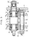
- FIG. 5 is a cross-sectional view of the shredding device taken along the line V - V in FIG. 3;
- FIG. 6 is a front view showing a modification of the shredding device; and
- FIG. 7 is a cross-sectional view which shows a modification of the shredding device.
- As shown in FIG. 1, a filter attachment is equipped with a
mainframe 1. Adrum train 2 is provided on the right side of themainframe 1. Thedrum train 2 extends to arolling section 3 on the left as observed in FIG. 1. - The
drum train 2 comprises many drums and the peripheral surface of each drum has many grooves (not shown) which are provided equidistantly. A cigarette rod produced by a cigarette manufacturing machine (not shown) is supplied to a groove of the grooved drum which is located at the right end of thedrum train 2, the cigarette rod having a length which corresponds to a double length cigarette. - Cigarette rods supplied to the
drum train 2 are successively transferred to the grooves of the grooved drums positioned at left by the rotating grooved drums of thedrum train 2 as publicly known, thus being carried toward therolling section 3. A grooved drum lying in the middle of thedrum train 2 has a rotary knife 4 and the rotary knife 4 cuts a cigarette rod, which has been carried in, into individual cigarettes as the grooved drum rotates. After that, the two cigarettes, which have been acquired by cutting the single cigarette rod, are carried toward the above-mentionedrolling section 3. In the course of the carrying process, a predetermined space is provided between the two cigarettes. - In FIG. 2, an area A₁ shows a processing flow from a step wherein individual cigarettes are formed from a cigarette rod to a step wherein the space is provided between the two cigarettes. In FIG. 2, a reference mark TR indicates the cigarette rod and a reference mark TS indicates the cigarettes.
- As shown in FIG. 1, above the
drum train 2 is provided ahopper 5. Thehopper 5 contains many filter rods which are not shown. The hopper 5 and thedrum train 2 are connected via adrum train 6 which is similar to thedrum train 2. - The
drum train 6 carries a filter rod, which has been taken out from thehopper 5, to thedrum train 2. In the course of the carrying process, the filter rod is equally cut into filter plugs of a specified length, then the filter plugs are supplied between the cigarettes on thedrum train 2. - More specifically, a grooved drum of the
drum train 6 located right below thehopper 5 is equipped with, for example, tworotary knives 7. Therotary knives 7 equally cut a filter rod, which is carried in as the grooved drum rotates, into three filter plugs. - A grooved drum located downstream from the grooved drum with the
rotary knives 7 functions as a "grading drum." The three filter plugs obtained from a single filter rod are placed one behind another in the carrying direction on the grading drum. Thus, the three filter plugs passing through the grading drum are fed to thedrum train 2 one by one from the grooved drum located at the downstream end of thedrum train 6. - Each of the filter plugs supplied to the
drum train 2 is arranged between two cigarettes at the aforementioned space. After that, the filter plug is carried with the two cigarettes to therolling section 3. - In FIG. 2, an area A₂ shows a processing flow from a step wherein individual filter plugs are acquired from a filter rod to a step wherein a filter plug is placed between the two cigarettes TS. In FIG. 2, a reference mark FR indicates the filter rod and a reference mark FP indicates the filter plug, the filter plug FP having a length which is equal to a double length filter chips, eace filter chip being to be attached to one cigarette TS.
- On the
drum train 2, the two cigarettes TS with the filter plug FP positioned between them are moved so that they come in close contact with the both ends of the filter plug FP when they pass through the last grooved drum of thedrum train 2. This processing is shown by an area A₃ in FIG. 2. - Hence, the two cigarettes TS are fed with the single filter plug FP from the
drum train 2 to the rollingsection 3. - On the other hand, a paper piece with glue on one surface thereof is also fed to the rolling
section 3. The paper piece feeding system extends from the top left end of themainframe 1 to the rollingsection 3 in FIG. 1. - The feeding system has a pair of paper rolls 7 and 8 at the top left of the
mainframe 1. These paper rolls 7 and 8 comprise reels wrapped with paper webs PW in multiple layers. The width of the paper web PW is sufficiently larger than the length of the filter plug FP. - Under the condition shown in FIG. 1, the paper web PW is drawn out from the
paper roll 7, and the drawn-out paper web PW is led to the rollingsection 3 while it is guided bymultiple guide rollers 9 which define the feeding route. In the middle of the feeding route, there is areservoir 10 for the paper web PW on the side of the paper rolls 7 and 8. Thereservoir 10 is used to absorb a difference between the consuming speed of the paper web PW on the rollingsection 3 and the feeding-out speed of the paper web PW on the paper roll side when the filter attachment is shut down or to temporarily accumulate the paper web PW prior to the connection of the paper webs PW. - The following describes the connection of the paper webs PW. A connecting
section 11 is provided on the upstream side of thereservoir 10. The leading end of the paper web PW drawn out from theother paper roll 8 is led to the connectingsection 11 in advance. If the paper web PW is stored in thereservoir 10, when the paper web PW of thepaper roll 7 is consumed and then the trailing end of the paper web PW reaches the connectingsection 11, the drawing out of the paper web PW from thepaper roll 7 is stopped, then the leading end of the paper web PW drawn out from thepaper roll 8 can be connected to the trailing end of the paper web PW. Even while the connection is being performed, the paper web PW continues to be fed from thereservoir 10 to the rollingsection 3. - In the feed path of the paper web PW, a gluing device 12 is provided on the side of the rolling
section 3. The gluing device 12 comprises anintermediate roller 13 which rotates while it is partially immersed in the glue of a glue container which is not shown, and atransfer roller 14 which rotates while being in contact with theintermediate roller 13 on one side and which rotates while being in contact with one surface of the paper web PW on the other side. - The glue which is applied from the glue container to the peripheral surface of the
intermediate roller 13 is transferred from theintermediate roller 13 to thetransfer roller 14. At this time, the glue is spread to a specified thickness and applied to the peripheral surface of thetransfer roller 14 then it is transferred to one surface of the paper web PW from thetransfer roller 14. The details of the gluing device 12 are disclosed in the publication of examined JP patent application No. S63-43077. - In the feeding route of the paper web PW, there are a pre-heater 15 and a post-heater 16 with the gluing device 12 located between them. These pre-heater 15 and the post-
heater 16 have guide plates for the paper web PW and heat- generating sheets attached to the surfaces of the guide plates, the guide plates and heat-generating sheets defining the carrying surface of the paper web PW. As it is obvious from FIG. 1, the pre-heater 15 heats the surface of the paper web PW to which the glue is applied, while the post-heater 16 heats the other surface of the paper web PW. - In the case of this embodiment, the post-heater 16 is combined with a hot-
air heater 17 which blows hot air to the glue applied to the paper web PW, thus effectively pre- drying the glue of the paper web PW. - A shredding
device 18 is provided at the end of the feeding route of the paper web PW. Thisshredding device 18 cuts the paper web PW with the glue on into paper pieces of a specified length, then the paper pieces are fed to the rollingsection 3. - The shredding
device 18 is equipped with a receivingdrum 19, the peripheral surface of the receivingdrum 19 being formed as a suction surface for suction of air from outside. In the vicinity of the receivingdrum 19, there is abladed drum 20, and thesedrums - When the paper web PW with the glue on reaches the receiving
drum 19, the surface of the paper web PW with no glue on is suctioned to the suction surface of the receivingdrum 19 and it is supplied to the rollingsection 3 as the receivingdrum 19 rotates. Although it is not shown in FIG. 1, thebladed drum 20 has a plurality of shredding blades installed circumferentially at equal intervals on its peripheral surface. Hence, the paper web PW suctioned to the peripheral surface of the receivingdrum 19 passes between the receivingdrum 19 and thebladed drum 20 as the receivingdrum 19 rotates. At this time of passing, the paper web PW is cut into the paper pieces by the shredding blades of the rotatingbladed drum 20. As a result, the paper pieces are formed on the receivingdrum 19. After that, the individual paper pieces are supplied to the rollingsection 3 in succession as the receivingdrum 19 rotates with the paper pieces suctioned to the receivingdrum 19. - When the two cigarettes TS are supplied with the filter plug FP from the end of the
aforementioned drum train 2 to the rollingsection 3, these cigarettes TS and the filter plug FP roll between the receivingdrum 19 and the rollingsection 3. Also, when a paper piece is supplied to the rollingsection 3, the paper piece is attached to a section extending from the end of one cigarette TS to the end of the other cigarette TS with the filter plug FP between them, and the paper piece is wrapped around the cigarettes and the filter plug as the cigarettes and the filter plug rotate. As a result, the two cigarettes TS and the filter plug FP are interconnected by the ring-like paper piece, thus producing a double filler cigarette which is equivalent to two filter cigarettes. After that, the double filter cigarette is supplied from the rollingsection 3 to adrum train 21. Thedrum train 21 extends toward the left end of themainframe 1. - By the time the paper piece is glued onto the cigarettes TS and the filter plug FP, the suction applied to the paper piece by the receiving
drum 19 has, of course, been released. - An area A₄ in FIG. 2 shows a processing flow from the supply of a paper piece to the rolling
section 3 to the wrapping of the paper piece. A reference mark PC indicates the paper piece, and the surface of the paper piece PC to which the glue has been applied is shown hatched. - After the double filter cigarette is supplied from the rolling
section 3 to thedrum train 21, it is carried on the grooved drums of thedrum train 21. One of the grooved drums of thedrum train 21 has arotary knife 22. When the double filter cigarette with the filter plug passes through therotary knife 22, the knife cuts the double filter cigarette at the middle of its filter plug. As a result, two cigarettes with filter chips or two filter cigarettes are obtained from the double filter cigarette on thedrum train 21. - After that, the two filter cigarettes are transferred from the end of the
drum train 21 to aconveyer unit 70. Theconveyer unit 70 carries the filter cigarettes to a packing machine (not shown) in the next stage, the filter cigarettes being arranged in the same direction while they are being carried in theconveyer unit 70. - An area A₅ in FIG. 2 shows the processing flow from cutting the double filter cigarettes, to carrying them to the packing machine. In FIG. 2, a reference mark FC denotes the filter chip obtained by cutting the filter plug FP.
- Referring now to FIG. 3 through FIG. 5, the details of the
aforementioned shredding device 18 are shown. The following describes the shreddingdevice 18 in detail. - As shown in FIG. 3, the receiving
drum 19 has adrum shaft 23, and one end of thedrum shaft 23 is rotatably supported by themainframe 1, while its other end is rotatably supported by the bottom section of asupport arm 24. Although it is not shown, one end of thedrum shaft 23 is connected to the driving source to receive power from the driving source so that thedrum shaft 23, i.e., the receivingdrum 19, is rotated in a specified direction. - The
support arm 24 is shaped approximately like an upside-down "L," and it is obvious from FIG. 3 that it extends in parallel with themainframe 1. The top end of thesupport arm 24 is fixed onto themainframe 1 through abracket 25. In other words, thebracket 25 is provided with abase plate 26 installed along themainframe 1 and ashoulder block 27 which projects from one end of thebase plate 26. The top end of thesupport arm 24 is fixed to the distal end theshoulder block 27 via a plurality of connectingbolts 28. - On the other hand, the
base plate 26 is fixed to themainframe 1 via a plurality of connectingbolts 29. As it is obvious from FIG. 3, thebase plate 26 extends facing the upper portion of thesupport plate 24. - A rocking
shaft 30 extends from one end of thebase plate 26 to the central part of thesupport arm 24. The rockingshaft 30 extends in parallel to thedrum shaft 23 of the receivingdrum 19, both ends thereof being held by thesupport arm 24 and thebase plate 26. - The rocking
shaft 30 has a pair of rockingarms arms shaft 30 viaplain bearings 33 as shown in FIG. 5 so that they can rotate. Aspacer sleeve 34 is mounted on the rockingshaft 30 at between the upper ends of the rockingarms spacer ring 35 is mounted between the upper end of the rockingarm 31 and thesupport arm 24. Hence, the mounting positions of the rockingarms shaft 30 are determined by thespacer sleeve 34 and thespacer ring 35. - A
drum shaft 36 of thebladed drum 20 extends between the bottom ends of the rockingarms drum shaft 36 extends in parallel to thedrum shaft 23 of the receivingdrum 19, both ends thereof being rotatably supported by the bottom ends of the rockingarms bearings 37. - To be more specific, the
drum shaft 36 has small-diameter portions diameter portions arms bearings 37. - The small-
diameter portion 36a of thedrum shaft 36, which is located on the side of themainframe 1, penetrates themainframe 1 via anOldham coupling 38, theOldham coupling 38 being supported by themainframe 1. - The small-
diameter portion 36a penetrating theOldham coupling 38 is connected to aninput shaft 39. Theinput shaft 39 is provided with aninput gear 40. Motive power is transmitted to theinput gear 40 via a gear train which is not shown. - Hence, when the
input gear 40, i.e.,input shaft 39, is rotated, the driving force is transmitted to thedrum shaft 36 via theOldham coupling 38, thus causing thedrum shaft 36 to rotate with theinput shaft 39. TheOldham coupling 38 has a function that ensures transmission of the motive power from theinput shaft 39 to thedrum shaft 36 while making theinput shaft 39 anddrum shaft 36 run at the same rotational speed even if the rockingarms input shaft 39 and thedrum shaft 36. - A pair of
free rollers 42 are mounted on the small-diameter portions drum shaft 36 viabearings 41 so that they can rotate. Thesefree rollers 42 are located between the corresponding rocking arm and the large-diameter portion of thedrum shaft 36, respectively. - Each of the
free rollers 42 includes aroller body 42a made of cemented carbide andring holders 42b attached to both surfaces of theroller body 42a viascrews 42c which penetrate theroller bodies 42a. Further, eachholder ring 42b is supported by thedrum shaft 36 via bearings so that they can rotate. - The portion of the
drum shaft 36 located between thefree rollers 42, i.e., the large-diameter portion of the drum shaft, is provided with thebladed drum 20, thebladed drum 20 rotating as one piece with thedrum shaft 36. Thebladed drum 20 is made of cemented carbide similar to that of theroller body 42a of thefree roller 42, and a plurality of shreddingblades 44 are provided on the peripheral surface of the bladed drum. Theseshredding blades 44 are arranged equidistantly on the periphery of thebladed drum 20, the blade edges extending in the axial direction of thedrum shaft 36. The blade edge of eachshredding blade 44 has a trapezoid section although it is not shown. The trapezoid shape is suited for shredding the paper web PW without contacting the receivingdrum 19 as described in the aforementioned publication of examined JP patent application No. S61- 54559. - The
shoulder block 27 of theaforementioned bracket 25 incorporates a pair of urging mechanism for pressing the rockingarms free rollers 42, against the peripheral surface of the receivingdrum 19. The urging mechanisms share the same structure; therefore, the following explains about only one of the urging mechanisms. - The
shoulder block 27 has asurface 27a which faces thebladed drum 20, thesurface 27a having a bottomedhole 58. Aslider 45 is fitted in thehole 58 so that it can slide, one end surface of theslider 45 facing the bottom surface of thehole 58, while the other end surface facing the open side of thehole 58. - A threaded
shaft 46 coaxially extends from one end surface of theslider 45; the threadedshaft 46 is screwed into the bottom surface of thehole 58 and it protrudes outside theshoulder block 27. The projection of the threadedshaft 46 has anut 47 which determines the axial position of theslider 45 in thehole 58. - A
guide shaft 48 coaxially extends from the other end surface of theslider 45, while apusher 49 is provided on the open side of thehole 58. Thepusher 49 has ashaft 50 on the side of thehole 58, theshaft 50 having aguide hole 50a. Theguide shaft 48 of theslider 45 is slidably fitted into theguide hole 50a of thepusher 49, thepusher 49 thus being supported by theslider 45. - The
pusher 49 has aflange 51, and between theflange 51 and theslider 45 is provided a compression coil spring, i.e., apressure spring 52, which surrounds theguide shaft 48 and theshaft 50. Thepressure spring 52 presses thepusher 49 against the rockingarm 31 with a specified pressing force. The pressing force can be adjusted by loosening thenut 47 and changing the axial position of the threadedshaft 46. - In FIG. 4, although the other urging mechanism is only partially shown, the
pusher 49 of the urging mechanism also urges the rockingarm 32 with a specified pressing force. - As described above, the
pushers 49 apply pressure to the rockingarms arms drum 19. As a result, the pair offree rollers 42 are kept in contact with the peripheral surface of the receivingdrum 19 with the specified pressing force. - The pair of
free rollers 42 has an outside diameter which is slightly larger than the outside diameter of thebladed drum 20, i.e., the outside diameter of the rotational trajectory of the blade edges of theshredding blades 44. Hence, when the pair offree rollers 42 rotate while being in contact with the receivingdrum 19, theshredding blades 44 do not touch the peripheral surface of the receivingdrum 19 even when the receivingdrum 19 and thebladed drum 20 are rotated in opposite directions from each other. In other words, even when theshredding blades 44 come closest to the peripheral surface of the receivingdrum 19, a gap (not shown) is secured between the peripheral surface of the receivingdrum 19 and the edges of theshredding blades 44, the gap being sufficiently smaller than the thickness of the paper web PW. - According to the shredding device described above, while the receiving
drum 19 and thebladed drum 20 are rotating, the paper web PW is supplied between the receivingdrum 19 and thebladed drum 20, then when the paper web PW passes between thedrums shredding blades 44. After that, the paper pieces PC are supplied to the rollingsection 3 as previously described. - Since the foregoing gap is secured between the shredding
blades 44 of thebladed drum 20 and the peripheral surface of the receivingdrum 19 when the paper web PW is cut, theshredding blades 44 do not bump against the receivingdrum 19, making it possible to prevent noises from the cutting or damage to theshredding blades 44 or the peripheral surface of the receivingdrum 19. - As previously described, the pair of rocking
arms drum 19. Accordingly, even if the rotation of the receivingdrum 19 develops run-out while the paper web PW is being cut, the pair offree rollers 42 do not come apart from the peripheral surface of the receivingdrum 19. In other words, the rocking position of the rockingarms drum 19; therefore, the pair of rotatingfree rollers 42 are maintained securely in contact with the peripheral surface of the receivingdrum 19. - Thus, since the
free rollers 42 and thebladed drum 20 are mounted on thedrum shaft 36 common to them, the gap between the shreddingblades 44 of thebladed drum 20 and the peripheral surface of the receivingdrum 19 is maintained at the constant dimension at all times during the cutting process. As a result, the paper web PW is cut reliably and stably. - Furthermore, even if the rotation of the receiving
drum 19 incurs run-out, the aforementioned gap is securely maintained, and therefore, theshredding blades 44 of thebladed drum 20 do not bump against the receivingdrum 19, thus preventing damage to the blade edges of theseshredding blades 44. - Also, the rocking
arms free rollers 42 and the receivingdrum 19, thus protecting these bearings from deformation or deterioration due to overheat. - Referring to FIG. 6 and FIG. 7, a modification of the shredding device is shown. To explain about the shredding device according to the modification, the same reference numbers are given to the components and portions which have the same functions as those in the previous embodiment, thus omitting the description of the components and portions. The following describes only the points which differ from the aforementioned embodiment.
- In the shredding device of the modification, the urging mechanism is equipped with an
air cylinder 53 in place of thepressure spring 52 as shown in FIG. 6, and thepusher 49 is installed on the end of apiston rod 54 of theair cylinder 53. In the case of this modification, thepusher 49 is in contact with the corresponding rockingarm 31 via aplate member 55. - Thus, even when the
air cylinder 53 is used in place of thepressure spring 52, theair cylinder 53 urges the corresponding rocking arm in the same manner toward the receivingdrum 19. Hence, the shredding device of the modification also has the same advantages as the shredding device of the embodiment. - The bearing 41 of each
free roller 42 is installed not directly to the small-diameter portions drum shaft 36 but via aneccentric ring 56 as shown in FIG. 7. - The peripheral surface of the
eccentric ring 56 is formed as a mountingsurface 57 for thebearing 41 and it is eccentric to thedrum shaft 36. Anannular gap 70 is secured between theeccentric ring 56 and the small- diameter portion of thedrum shaft 36. The gap prevents theeccentric ring 56 from being rotated even when thedrum shaft 36 is rotated. - The
eccentric ring 56 is mounted on the corresponding rocking arm so that its angular position can be adjusted in relation to thedrum shaft 36. To be more specific, theeccentric ring 56 is installed on the corresponding rocking arm by four mountingbolts 60 shown in FIG. 6. All mountingbolts 60 are screwed into theeccentric ring 56, penetratingarc slots 61 formed in the rocking arm. - By changing the angular position of the
eccentric ring 56, the distance from the point of contact between the receivingdrum 19 and thefree rollers 42 to the axis of thedrum shaft 36 can be changed. Accordingly, even if the aforementioned gap decreases due to wornfree rollers 42, the gap can be readjusted to a desired value simply by adjusting the angular position of theeccentric ring 56 in relation to thedrum shaft 36. Also, even if the aforementioned gap increases due toground shredding blades 44 of thebladed drum 20, the gap can be maintained at a constant value by adjusting the angular position of theeccentric ring 56.
Claims (9)
- A shredding device for a paper web(PW) used in the manufacture of cigarettes with filters, including a first drum(19) rotatably arranged and having a peripheral surface for carrying paper web(PW) as said first drum(19) rotates; and shredding means for shredding the paper web(PW) into paper pieces of a specified length, in cooperation with said first drum(19), said shredding means including a common shaft(36) arranged in parallel to said first drum(19) and being rotated in the opposite direction from said first drum(19), a second drum(20) mounted on the common shaft(36) arranged in parallel to said first drum(19) and being rotated with said common shaft(36), a pair of free rollers(42) rotatably mounted on the common shaft at both sides of said second drum(20) and having a larger outside diameter than said second drum(20), said free roller(42) being rotated while contacting the peripheral surface of said first drum(19) as said first drum rotates, and a plurality of shredding blades(44) arranged circumferentially on the peripheral surface of said second drum(20) at equal intervals, said shredding blades(44) passing said first drum(19) with a specified gap between themselves and the peripheral surface of said first drum(19) as said second drum(20) is rotated, shredding the paper web(PW) on said first drum(19) while passing,
characterized in that said shredding means further comprises supporting means(30,31,32) for supporting said second drum(20) and said pair of free rollers(42) so that they are allowed to move toward or away from the peripheral surface of said first drum(19), and urging means(49,52) for urging said second drum(20) and said pair of free rollers(42) toward the peripheral surface of said first drum(19), said the pair of free rollers(42) being pressed against the peripheral surface of said first drum(19) with a specified force. - The device according to claim 1,
characterized in that said supporting means includes a fixed shaft(30) arranged in parallel to said common shaft(36), and a pair of supporting arms(31,32) rotatably supported on the fixed shaft(30), said common shaft(36) being rotatably supported by the supporting arms(31,32). - The device according to claim 2,
characterized in that said urging means includes a pair of pushers(49), which are in contact with the supporting arms(31,32), and a pair of pressure springs(52) pressing the support arms(31,32) toward said first drum(19) by means of the corresponding pusher(49). - The device according to claim 3,
characterized in that said urging means further includes adjusting means(45,46,47) for adjusting the urging force of the pressure springs(52). - The device according to claim 2,
characterized in that said urging means includes a pair of pushers(49), which are in contact with the supporting arms(31,32), and a pair of air cylinders(53) pressing the supporting arms(31,32) toward said first drum(19) by means of the corresponding pusher(49). - The device according to claim 2,
characterized in that said device further includes an Oldham coupling(38) connected to one end of said common shaft(36) to transmit motive power to said common shaft(36). - The device according to claim 2,
characterized in that said supporting means further includes eccentric rings(56) eccentrically surrounding said common shaft(36) and are fixed to its corresponding supporting arm(31,32), and bearings(41) mounted on the eccentric rings(56), respectively, said pair of free rollers(42) being rotatably supported on the bearings(41). - The device according to claim 7,
characterized in that said supporting means further includes an annular gap(70) defined between said common shaft(36) and the eccentric ring(56). - The device according to claim 8,
characterized in that said supporting means further includes adjusting means(60,61) for adjusting a angular position of the eccentric ring(56) in relation to said common shaft(36).
Applications Claiming Priority (3)
| Application Number | Priority Date | Filing Date | Title |
|---|---|---|---|
| JP165877/92 | 1992-06-24 | ||
| JP16587792A JP3293174B2 (en) | 1992-06-24 | 1992-06-24 | Chip paper cutting device |
| JP16587792 | 1992-06-24 |
Publications (3)
| Publication Number | Publication Date |
|---|---|
| EP0576005A2 true EP0576005A2 (en) | 1993-12-29 |
| EP0576005A3 EP0576005A3 (en) | 1995-08-30 |
| EP0576005B1 EP0576005B1 (en) | 2000-08-30 |
Family
ID=15820680
Family Applications (1)
| Application Number | Title | Priority Date | Filing Date |
|---|---|---|---|
| EP93110112A Expired - Lifetime EP0576005B1 (en) | 1992-06-24 | 1993-06-24 | Cutting device for paper web used in the manufacture of cigarettes with filters |
Country Status (4)
| Country | Link |
|---|---|
| US (1) | US5350126A (en) |
| EP (1) | EP0576005B1 (en) |
| JP (1) | JP3293174B2 (en) |
| DE (1) | DE69329315T2 (en) |
Cited By (1)
| Publication number | Priority date | Publication date | Assignee | Title |
|---|---|---|---|---|
| EP0911125A1 (en) * | 1997-10-22 | 1999-04-28 | Sms Schloemann-Siemag Aktiengesellschaft | High speed cutter for rolled web |
Families Citing this family (2)
| Publication number | Priority date | Publication date | Assignee | Title |
|---|---|---|---|---|
| CN110290715B (en) * | 2017-02-28 | 2021-11-09 | 菲利普莫里斯生产公司 | Apparatus and method for processing packaging material |
| CN112808389B (en) * | 2021-03-22 | 2025-07-25 | 天地上海采掘装备科技有限公司 | Swing type crushing mechanism driven by rocker arm power |
Family Cites Families (7)
| Publication number | Priority date | Publication date | Assignee | Title |
|---|---|---|---|---|
| GB1050754A (en) * | 1964-09-01 | 1900-01-01 | ||
| US4095498A (en) * | 1976-06-14 | 1978-06-20 | Frank M. Biggar, Jr. | Diecutter |
| US4226150A (en) * | 1978-08-15 | 1980-10-07 | Avery International Corporation | Deflectable bearer roll |
| JPS59115198A (en) * | 1982-12-22 | 1984-07-03 | 日本たばこ産業株式会社 | Cutter for cork paper |
| US4576339A (en) * | 1983-05-10 | 1986-03-18 | Uniroyal, Inc. | Scrap tire cutting apparatus |
| JPS6154559A (en) * | 1984-08-23 | 1986-03-18 | Fuji Xerox Co Ltd | Japanese word processor |
| AU7859491A (en) * | 1990-05-10 | 1991-11-27 | Byron L. Buck | Rotary die cutting system for sheet material |
-
1992
- 1992-06-24 JP JP16587792A patent/JP3293174B2/en not_active Expired - Fee Related
-
1993
- 1993-06-23 US US08/088,422 patent/US5350126A/en not_active Expired - Fee Related
- 1993-06-24 DE DE69329315T patent/DE69329315T2/en not_active Expired - Fee Related
- 1993-06-24 EP EP93110112A patent/EP0576005B1/en not_active Expired - Lifetime
Cited By (3)
| Publication number | Priority date | Publication date | Assignee | Title |
|---|---|---|---|---|
| EP0911125A1 (en) * | 1997-10-22 | 1999-04-28 | Sms Schloemann-Siemag Aktiengesellschaft | High speed cutter for rolled web |
| CN1131755C (en) * | 1997-10-22 | 2003-12-24 | Sms舒路曼-斯玛公司 | High-speed shearer for cross shearing rolled strip steel |
| US7107891B2 (en) * | 1997-10-22 | 2006-09-19 | Sms Schloemann-Siemag Aktiengesellschaft | High-speed shear for transversely cutting rolled strip |
Also Published As
| Publication number | Publication date |
|---|---|
| JPH067140A (en) | 1994-01-18 |
| US5350126A (en) | 1994-09-27 |
| EP0576005A3 (en) | 1995-08-30 |
| EP0576005B1 (en) | 2000-08-30 |
| JP3293174B2 (en) | 2002-06-17 |
| DE69329315T2 (en) | 2001-01-04 |
| DE69329315D1 (en) | 2000-10-05 |
Similar Documents
| Publication | Publication Date | Title |
|---|---|---|
| US4485710A (en) | Apparatus for severing running webs of tipping paper or the like | |
| US4594928A (en) | Knife cylinder for working weblike material | |
| JP5179709B2 (en) | Anvil for rotary cutting unit, rotary cutting unit having this anvil, and cutting method using this rotary cutting unit | |
| US20110036220A1 (en) | Method and Apparatus for Dry Lubrication of a Thin Slitting Blade | |
| US6609997B1 (en) | Method and apparatus for resurfacing anvil blanket of a rotary diecutter for box making machine | |
| US5820041A (en) | Food cutting apparatus | |
| US5465641A (en) | Cylinder for processing | |
| EP0576005B1 (en) | Cutting device for paper web used in the manufacture of cigarettes with filters | |
| EP0576006B1 (en) | Shredding device for paper web used in the manufacture of cigarettes with filters | |
| GB1569124A (en) | Production of two-piece wrappers | |
| KR930017686A (en) | Machines and methods for cutting rolls such as paper | |
| US5857396A (en) | Slitting machine | |
| KR101215786B1 (en) | Rotary cutter provided with an air distribution assembly | |
| US4211135A (en) | Cutting width modifying means for a longitudinal web cutting machine | |
| EP3462928B1 (en) | Apparatus and method for manufacturing tobacco industry products | |
| CN1972785A (en) | Rotary cutter and rotary cutting apparatus provided with the rotary cutter | |
| CN101376224A (en) | Method and device for grinding cutting blades | |
| CN1972787B (en) | Anvil for rotary cutting device and rotary cutting device with anvil | |
| CA2235333A1 (en) | Apparatus for cutting and grinding a workpiece | |
| JPH037568A (en) | Method of regulating and controlling equipment for cutting strip material | |
| US7185840B2 (en) | Web winding apparatus | |
| JP2005160477A (en) | Device for separating tobacco from tobacco cake and method for the same | |
| JP2003503224A (en) | Force-adjustable rotating device for web processing | |
| CN1907705B (en) | Folding cylinders for folding machines of printing presses | |
| JP2544424Y2 (en) | Die cutter roll device |
Legal Events
| Date | Code | Title | Description |
|---|---|---|---|
| PUAI | Public reference made under article 153(3) epc to a published international application that has entered the european phase |
Free format text: ORIGINAL CODE: 0009012 |
|
| 17P | Request for examination filed |
Effective date: 19930701 |
|
| AK | Designated contracting states |
Kind code of ref document: A2 Designated state(s): DE GB IT |
|
| PUAL | Search report despatched |
Free format text: ORIGINAL CODE: 0009013 |
|
| AK | Designated contracting states |
Kind code of ref document: A3 Designated state(s): DE GB IT |
|
| 17Q | First examination report despatched |
Effective date: 19971024 |
|
| GRAG | Despatch of communication of intention to grant |
Free format text: ORIGINAL CODE: EPIDOS AGRA |
|
| RTI1 | Title (correction) |
Free format text: CUTTING DEVICE FOR PAPER WEB USED IN THE MANUFACTURE OF CIGARETTES WITH FILTERS |
|
| GRAG | Despatch of communication of intention to grant |
Free format text: ORIGINAL CODE: EPIDOS AGRA |
|
| GRAH | Despatch of communication of intention to grant a patent |
Free format text: ORIGINAL CODE: EPIDOS IGRA |
|
| GRAH | Despatch of communication of intention to grant a patent |
Free format text: ORIGINAL CODE: EPIDOS IGRA |
|
| GRAA | (expected) grant |
Free format text: ORIGINAL CODE: 0009210 |
|
| AK | Designated contracting states |
Kind code of ref document: B1 Designated state(s): DE GB IT |
|
| REF | Corresponds to: |
Ref document number: 69329315 Country of ref document: DE Date of ref document: 20001005 |
|
| ITF | It: translation for a ep patent filed | ||
| EN | Fr: translation not filed | ||
| PLBE | No opposition filed within time limit |
Free format text: ORIGINAL CODE: 0009261 |
|
| STAA | Information on the status of an ep patent application or granted ep patent |
Free format text: STATUS: NO OPPOSITION FILED WITHIN TIME LIMIT |
|
| 26N | No opposition filed | ||
| REG | Reference to a national code |
Ref country code: GB Ref legal event code: IF02 |
|
| PGFP | Annual fee paid to national office [announced via postgrant information from national office to epo] |
Ref country code: GB Payment date: 20050622 Year of fee payment: 13 |
|
| PGFP | Annual fee paid to national office [announced via postgrant information from national office to epo] |
Ref country code: DE Payment date: 20050630 Year of fee payment: 13 |
|
| PG25 | Lapsed in a contracting state [announced via postgrant information from national office to epo] |
Ref country code: GB Free format text: LAPSE BECAUSE OF NON-PAYMENT OF DUE FEES Effective date: 20060624 |
|
| PGFP | Annual fee paid to national office [announced via postgrant information from national office to epo] |
Ref country code: IT Payment date: 20060630 Year of fee payment: 14 |
|
| PG25 | Lapsed in a contracting state [announced via postgrant information from national office to epo] |
Ref country code: DE Free format text: LAPSE BECAUSE OF NON-PAYMENT OF DUE FEES Effective date: 20070103 |
|
| GBPC | Gb: european patent ceased through non-payment of renewal fee |
Effective date: 20060624 |
|
| PG25 | Lapsed in a contracting state [announced via postgrant information from national office to epo] |
Ref country code: IT Free format text: LAPSE BECAUSE OF NON-PAYMENT OF DUE FEES Effective date: 20070624 |