EP0576014A2 - Beam scanning apparatus - Google Patents
Beam scanning apparatus Download PDFInfo
- Publication number
- EP0576014A2 EP0576014A2 EP93110128A EP93110128A EP0576014A2 EP 0576014 A2 EP0576014 A2 EP 0576014A2 EP 93110128 A EP93110128 A EP 93110128A EP 93110128 A EP93110128 A EP 93110128A EP 0576014 A2 EP0576014 A2 EP 0576014A2
- Authority
- EP
- European Patent Office
- Prior art keywords
- face
- scanning apparatus
- beam scanning
- lens
- entrance
- Prior art date
- Legal status (The legal status is an assumption and is not a legal conclusion. Google has not performed a legal analysis and makes no representation as to the accuracy of the status listed.)
- Granted
Links
Images


Classifications
-
- G—PHYSICS
- G02—OPTICS
- G02B—OPTICAL ELEMENTS, SYSTEMS OR APPARATUS
- G02B26/00—Optical devices or arrangements for the control of light using movable or deformable optical elements
- G02B26/08—Optical devices or arrangements for the control of light using movable or deformable optical elements for controlling the direction of light
- G02B26/10—Scanning systems
- G02B26/108—Scanning systems having one or more prisms as scanning elements
Definitions
- the present invention relates to a beam scanning apparatus especially for use with laser beam printers or the like.
- a beam scanning apparatus especially for use with laser beam printers or the like is adapted in such a way that a light beam issuing from a light source such as a semiconductor laser is normally collimated with a collimator lens, then deflected for scanning with a rotating polygonal mirror and passed through an imaging lens to form a focused beam spot on an imaging plane.
- a light source such as a semiconductor laser
- the conventional beam scanning apparatus suffers from the problem that the diameter of the imaging lens is a large as about 100 mm and that the size of the polygonal mirror is about 20 mm in terms of the radius of the inscribed circle.
- the conventional beam scanning apparatus is unavoidably bulky in size.
- the present invention has been accomplished under these circumstances and has an object to provide a novel beam scanning apparatus that satisfies both the requirement for smaller size and lower cost. This object is solved by the beam scanning apparatus of independent claim 1. Further advantageous features, aspects and details of the invention are evident from the dependent claims, the description and the drawings. The claims are intended to be understood as a first non-limiting approach of defining the invention in general terms.
- the present invention attains the above-described and other objects according to a specific aspect by a beam scanning apparatus in which a reflecting face, as well as an entrance face and an exit face - at least one of which is so specified for shape as to be capable of correcting aberrations - are pravided for an optical element that is driven by a rotational drive means to rotate and deflects a beam from a beam generator.
- the single optical element is rotated as a beam incident on the entrance face is deflected by the reflecting face to leave the rotating element through the exit face while, at the same time, the necessary aberrational corrections are made to insure that the beam scanning over the imaging plane will be focused as a spot.
- Figs. 1 to 4 show a typical example of the beam scanning apparatus of the present invention.
- a light beam issuing from a semiconductor laser 1 is collimated by a collimator lens 2; the beam then falls on the entrance face S1 of a rotating lens mirror 3 as an optical element and is reflected by the reflecting face S2 of the mirror 3 so that it will emerge from the lens mirror 3 through the exit face S3.
- the entrance face S1 and the exit face S3 are formed to provide a concave and a convex, respectively; the two faces are so set that a light beam scanning at the scan center will pass through those faces perpendicularly.
- the reflecting face S2 is so set that the light beam scanning at the scan center will be incident on that face at an angle of 45°.
- the rotating lens mirror 3 is adapted in such a way that the rotating axis 0 is included in the reflecting S2 and will pass through the point of reflecting of the light beam scanning at the scan center.
- the rotating lens mirror 3 is so adapted that the optical axes of the entrance face S1 and the exit face S3 will coincide with the optical path of the light beam scanning at the scan center. Therefore, the light beam is deflected as the lens mirror 3 is rotated and the deflected light beam will form a spot on the plane 5 as it is scanned.
- an imaging lens may be provided between the lens mirror 3 and the scanning plane 5; in this way, the optical characteristics of the system are further enhanced and the greater the number of imaging lenses used, the better are the optical characteristics that can be attained.
- Fig. 3 depicts how the light beam is deflected as a function of the rotation of the lens mirror 3.
- the lens mirror 3 basically rotates about the rotating center 0 in the reflecting face S2 to be displaced in position as indicated by I, II and III.
- the incident light beam L will fall on the entrance face S1 in different positions at different angles of incidence; hence, the beam L is deflected under the action of different refractive powers.
- the incident beam is then reflected by the reflecting face S2 and deflected at a greater angle.
- the beam is subjected to different refractive powers depending upon the position of the rotating lens mirror 3 and it is eventually deflected to produce an emerging beam M1, M2 or M3.
- the entrance face S1 and the exit face S3 are curved, the light beam is subjected to either a diverging or a converging action.
- the entrance face S1 of the lens mirror 3 is rendered concave whereas the exit face S3 is rendered convex and because of this design, the lens mirror 3 proves to be very effective in correcting aberrations.
- the laser beam to be produced has a small diameter, so among the various aberrations that develop in the optics, one only need consider the following three as principal types: curvature of the field, astigmatism and distortion characteristics. Distortion is worth special mention since a negative distortion characteristic which is generally called “an f ⁇ characteristic" is provided and this is due to the fact that the uniform angular velocity motion of the rotating polygonal mirror must be transformed to the uniform velocity motion of an imaging spot on the scanning plane.
- Fig. 4 shows a cross section of the optics in the example under consideration as it is taken in the main scanning direction and developed with respect to the reflecting face S2 of the lens mirror 3.
- the optics in the example under consideration differs form the one used in the conventional beam scanning apparatus in that an optical surface (entrance face S1 of the lens mirror 3) is located in front of the entrance pupil P and this is equivalent to the case where the lens mirror 3 rotates through one half the incident angle of the light beam B.
- the entrance face S1 of the lens mirror 3 is located in front of the entrance pupil P and, hence, by making the entrance face S1 concave so that it will have a negative power, said face is allowed to serve two important purposes at the same time, i.e., producing a negative distortion and reducing the Petzval sum. Furthermore, the entrance face S1 and exit face S3 of the lens mirror 3 are rotated in the same directing through one half the incident angle of the light beam B; hence, the incident light beam will eventually cover only one half the view angle and the resulting decrease in the effective aperture helps reduce the size of the lens mirror 3 by a significant degree.
- an imaging lens may be used as an auxiliary means and, in this case, an imaging lens of a smaller diameter can be used with the conventional beam scanning apparatus.
- an imaging lens 4 having a positive power must be kept by a sufficient distance from the entrance pupil P to produce a negative distortion and this has unavoidably increased the aperture of the imaging lens 4; furthermore, high refractive index rather than low index has been a general requirement for the purpose of creating an adequately negative distortion.
- the system of the present invention which is shown in Fig. 5(b) allows both the lens mirror 3 and the imaging lens 4 to be responsible for the creation of a negative distortion; hence, the imaging lens 4 per se needs to develop only a small quantity of negative distortion, thereby permitting the imaging lens 4 to come closer to the entrance pupil and, hence, contributing to the reduction in its size.
- the decrease in the amount of negative distortion that is produced by the imaging lens 4 will contribute to a lower refractive index of this lens.
- the negative distortion that is developed at the entrance face S1 of the lens mirror 3 will prevent the incoming light beam from spreading excessively wide as it is launched into the imaging lens 4 and this is also effective in reducing the diameter of that lens.
- a single spherical lens element will suffice as the imaging lens if it is used at all. It should also be noted that if the imaging lens system is adapted to have a positive overall refractive power, a negative distortion for insuring scanning at uniform speed will be produced, thereby providing better optical characteristics for the beam scanning apparatus.
- the rotating axis of the lens mirror 3 is contained in the reflecting face S2.
- This enables the lens mirror 3 to be mounted on a rotating member such as a motor in an easy and highly precise manner since reference positions such as the center of rotation and the reflecting face are well defined.
- the composition of faces in the optics becomes substantially symmetric with respect to the scan center, thereby providing symmetry for aberrations and other optical characteristics.
- axially symmetric optics alone as typified by a spherical lens will suffice for correcting aberration characteristics and the like.
- a single lens mirror 3 is used to insure that one scan is performed per rotation of the motor. It should, however, be noted that there is no need to be bound by this requirement and two lens mirrors may be used. In this case, two scans are possible per rotation of the motor, contributing to a further increase in the scan speed. If there is the slightest departure from the symmetry of either lens mirror 3, the position of the scanning line will be offset to cause uneven scanning.
- the center of rotation lies on the reflecting face S2 and, hence, the above-described problem can be solved by insuring that the reflecting face S2 of one lens mirror is in close contact with the reflecting face of the other lens mirror.
- Figs. 6(a), (b) and (c) show three rotating lens mirrors 31, 32 and 33 that are adapted in such a way that the angle ⁇ formed between the entrance face S1 and the exit face S3 take on different values.
- the angle ⁇ is set in accordance with the angle ⁇ formed between optical axis M extending to the scanning plane 5 and the light beam issuing from the light source; however, from the viewpoint of aberrational correction, both the entrance face S1 and the exit face S3 are desirably set in such a way that the light beam scanning at the scan center will pass through those faces perpendicularly. In this case, the wider the angle ⁇ , the smaller the area that is required of the reflecting face S2.
- lens mirrors 31, 32 and 33 are rotated at high speed, their apices are desirably made arcuate in order to reduce the whine and air loss. Furthermore, if one wants to arrange a plurality of lens mirrors 3 in symmetry of rotation, the angle ⁇ should preferably be made wide enough to permit the provision of a greater number of lens mirrors 3 as shown in Fig. 7.
- the lens mirror 3 may be made of either optical glasses or optical plastics if neither the entrance face S1 nor the exit face S3 is aspheric; if these faces are aspheric, the lens mirror 3 is preferably made of optical plastics.
- An aluminum film or any other suitable reflecting layer may be formed on the reflecting face S2 by a suitable process such as evaporation. However, one may cause total reflection at the reflecting face S2 by making the angle ⁇ large enough to insure that the angle of incidence at that face is greater than the critical value. In this case, there is no need to provide a reflecting layer on the reflecting face S2.
- the angle through which the lens mirror 3 rotates for the time period from the start to the end of one scan is written as 2 ⁇ and the following symbols are used to denote optical specifications: ri, the radius of curvature of the ith surface Si; and di, the on-axis distance from the ith surface to the next surface.
- ri the radius of curvature of the ith surface Si
- di the on-axis distance from the ith surface to the next surface.
- h2/ri zi h2/ri 1+ 1-(Ki+1) (h/ri)2 + Aih4 + bih6
- zi is the distance by which the point on the aspheric surface where the height from the optical axis is h is departed from the plane tangent to the vertex of the aspheric surface
- n1 and n2 are both the refractive indices of the lens mirror.
- the light source, the entrance face of the collimator lens, its exit face, the entrance face of the imaging lens, its exit face and the reflecting face of the concave mirror are denoted by S0, Sa, Sb, Sc, Sd and Se, respectively, whereas the refractive indices of the collimator lens and the imaging lens are denoted by n a and n c , respectively.
- the reflecting face of the lens mirror is planar.
- Fig. 8 shows a cross section of the beam scanning apparatus of Example 1 as it is taken the main scanning direction.
- the entrance face S1 of the lens mirror 3 is concave whereas the exit face S3 is convex.
- a light beam collimated by the collimator lens 2 is launched into the lens mirror 3.
- Figs. 9(a) and 9(b) are graphs plotting the aberrations that occur in the design of Example 1. Obviously, effective correction was achieved for both curvature of the field ( ⁇ 3 mm and less) and scanning linearity (2% and less).
- Fig. 10 shows a cross section of the beam scanning apparatus of Example 2 as it is take in the main scanning direction. As shown, the entrance face S1 of the lens mirror 3 is concave whereas the exit face S3 is convex.
- Example 2 differs from Example 1 in that an imaging lens 4 is inserted. A light beam collimated by the collimator lens 2 is launched into the lens mirror 3.
- Fig. 11 is a drawing that contains graphs plotting the aberrations that occur in the design of Example 2. Because of the insertion of the imaging lens 4, the system of Example 2 achieved even more satisfactory correction of aberrations than the system of Example 1.
- Fig. 12 shows a cross section of the beam scanning apparatus of Example 3 as it is taken in the main scanning direction.
- the entrance face S1 of the lens mirror 3 is convex whereas the exit face S3 is concave.
- Example 3 also differs from Example 1 in that an imaging lens 4 is inserted.
- a light beam collimated by the collimator lens 2 is launched into the lens mirror 3. If the focal length of the collimator lens 2 is the same, the optical power emitted from the semiconductor laser 1 is utilized more efficiently as the diameter of the collimated light beam increases.
- the entrance face S1 of the lens mirror 3 is convex whereas the exit face S3 is concave, the incident light beam launched into the lens mirror 3 is converged by the entrance face S1, thereby enabling the beam scanning apparatus to produce an increased optical power efficiency with the incident light beam having a larger diameter than the emerging light beam.
- Fig. 13 is a drawing that contains graphs plotting the aberrations that occur in the design of Example 3.
- Fig. 14 shows a cross section of the beam scanning apparatus of Example 4 as it is taken in the main scanning direction.
- Example 4 differs from Example 1 in that the entrance face S1 and exit face S3 of the lens mirror 3 are both concave and that an imaging lens 4 is inserted. A light beam collimated by the collimator lens 2 is launched into the lens mirror 3.
- Figs. 15(a) and 15(b) are graphs plotting the aberrations that occur in the design of Example 4.
- Fig. 16 shows a cross section of the beam scanning apparatus of Example 5 as it is taken in the main scanning direction.
- Example 5 differs from Example 1 in that the entrance face S1 of the lens mirror 3 is concave whereas the exit dace S3 is planar and that an imaging lens 4 is inserted.
- a light beam collimated by the collimator lens 2 is launched into the lens mirror 3. If either the entrance face S1 or the exit face S3 of the lens mirror 3 or both faces are made planar as in Example 5, the lens mirror 3 can be manufactured easily at a lower cost. It should also be mentioned that if one optical component has two curved optical surfaces, the precision of relative positions of their optical axes becomes a problem, demanding exact agreement between the two optical axes.
- Figs. 17(a) and 17(b) are graphs plotting the aberrations that occur in the design of Example 5.
- Fig. 18 shows a cross section of the beam scanning apparatus of Example 6 as it is taken in the main scanning direction.
- Example 6 differs from Example 1 in that the entrance face S1 of the lens mirror 3 is planar whereas the exit face S3 is concave and that an imaging lens 4 is inserted. A light beam collimated by the collimator lens 2 is launched into the lens mirror.
- Figs. 19(a) and 19(b) are graphs plotting the aberrations that occur in the design of Example 6.
- Fig. 20 shows a cross section of the beam scanning apparatus of Example 7 as it is taken in the main scanning direction.
- Example 7 differs from Example 1 in that the reflecting face S2 of the lens mirror 3 is spherical and that an imaging lens 4 is inserted. A light beam collimated by the collimator lens 2 is launched into the lens mirror 3. If the reflecting face S2 of the lens mirror 3 is rendered spherical as in Example 7, a higher degree of freedom is insured in optical design to provide better aberrational characteristics.
- Example 7 has the added advantage that the astigmatism that occurs in the semiconductor laser 1 serving as a light source can be corrected by the astigmatism that develops on the reflecting face S2.
- Figs. 21(a) and 21(b) are graphs plotting the aberrations that occur in the design of Example 7. Obviously, the median of the variation in the amount of field curvature in the main scanning direction is in substantial agreement with that in the sub-scanning direction.
- the beam scanning apparatus of Example 8 is characterized in that the entrance face S1 of the lens mirror 3 is aspheric, with an imaging lens being inserted. A light beam collimated by the collimator lens is launched into the lens mirror 3. If, as in Example 8, either the entrance face S1 or the exit face S3 of the lens mirror 3 or both faces are rendered aspheric, aberrations can be corrected in a satisfactory manner to insure that the beam scanning apparatus provides remarkable optical characteristics. To manufacture an aspheric surface at low cost, the use of a plastic lens is recommended. In this connection, making the lens mirror 3 from plastic materials is particularly desired since it is effective in reducing the rotational load.
- Figs. 22(a) and 22(b) are graphs plotting the aberrations that occur in the design of Example 8.
- Fig. 23 is a drawing that shows the beam scanning apparatus of Example 9; Fig. 23(a) shows a cross section as taken in the main scanning direction and Fig. 23(b) is a cross section as taken in the sub-scanning direction and developed with respect to the reflecting face S2.
- Example 9 the entrance face S1 and exit face S3 of the lens mirror 3 are both toric, with an imaging lens 4 being inserted.
- a light beam collimated by the collimator lens 2 is launched into the lens mirror 3.
- either the entrance face S1 or the exit face S3 of the lens mirror 3 or both faces are rendered toric to construct anamorphic scanning optics, aberrations can be corrected independently in the main and sub-scanning directions, thereby assuring excellent aberrational characteristics.
- Another advantage of the anamorphic optics is that it provides ease in performing an optical design for correcting the astigmatism that develops in the semiconductor laser 1 serving as the light source.
- only one of the two axially symmetric optical surface that compose the scanning optics may be rendered toric with slightly different curvatures being provided in two crossed directions to correct the astigmatism that develops in the semiconductor laser 1.
- Figs. 24(a) and 24(b) are graphs plotting the aberrations that occur in the design of Example 9.
- the beam scanning apparatus of Example 10 is characterized by the optical specifications of the lens mirror 3 that are set in such a way that despite variations in the refractive index of the lens mirror, the focal length of the scanning optics remains the same and, at the same time, the position of the image plane is invariable. Furthermore, an imaging lens is inserted and a light beam collimated by the collimator lens is launched into the lens mirror 3.
- the focal length of the overall system remains the same and the focal plane will not vary even if temperature variations and other environmental changes cause variations in the refractive index of the lens mirror 3.
- a beam scanning apparatus that operates very stably in the face of environmental variations and which exhibits satisfactory optical characteristics at all times. It should particularly be mentioned that since the lens mirror 3 has a special geometry that is quite different from ordinary optical lenses, it is desirably manufactured by the molding of optical plastics; however, optical plastics are subject to great variations in the refractive index caused by temperature changes and, hence, it is effective to determine the settings of the lens mirror 3 in such a way that the condition specified above is practically satisfied.
- Figs. 25(a) and 25(b) are graphs plotting the aberrations that occur in the design of Example 10.
- Fig. 26 shows a cross section of the beam scanning apparatus of Example 11 as it is taken in the main scanning direction.
- the rotating center O of the lens mirror 3 is located inward of the reflecting face S2 and an imaging lens 4 is also inserted.
- a light beam collimated by collimator lens 2 is launched into the lens mirror 3.
- Figs. 27(a) and 27(b) are diagrams comparing Examples 1 and 11 as regards the paths of a light beam that is deflected for scanning and travelling through the lens mirror 3.
- the lens mirror 3 in Example 1 rotates about the center O in the reflecting face S2 and, hence, the light beam travels through a wide area A to provide a large effective aperture at the entrance face S1, thereby limiting the angle through which the lens mirror 3 is rotated in association with the scan area.
- the rotating center O is set to lie within the lens mirror 3, particularly on the optical axis near the midpoint between the entrance face S1 and the reflecting face S2, the effective aperture at the entrance face S1 can reasonably be reduced and, at the same time, the effective aperture at the exit face S3 will not increase very much. If the effective aperture is small, the rotating angle of the lens mirror 3 can be increased, thereby realizing a compact beam scanning apparatus that requires a shorter optical path. Another advantage of the small effective aperture is that it provides ease in assuring high precision for lens surfaces.
- Figs. 28(a) and 28(b) are graphs plotting the aberrations that occur in the design of Example 11.
- Fig. 29 shows a cross section of the beam scanning apparatus of Example 12 as it is taken in the main scanning direction.
- the lens mirror 3 has the rotating center O located in its exterior and an imaging lens 4 is inserted.
- a light beam collimated by the collimator lens 2 is launched into the lens mirror 3.
- the lens mirror 3 must be installed further above the rotating shaft of the motor in order to avoid contact with it and this adds to the height of that portion.
- the rotating center O of the lens mirror 3 is located exterior to it in such a position that the scanning light beam will not pass, the mirror 3 will not interfere with the rotating shaft 6 of the motor as shown in Fig. 30 and the height of that portion can accordingly be lowered.
- the deflector sets the height of all of its portions, so reducing the height of that portion is advantageous for the purpose of realizing a compact system.
- Fig. 31 it also becomes possible to arrange three or more lens mirrors 3 around the rotating shaft 6 as shown in Fig. 31 and this provides a favorable condition for increasing the scan speed.
- the structural feature under discussion is also advantageous for arranging a plurality of lens mirrors 3 with the angle between the optical axes of the entrance face S1 and the exit face S3 being reduced (namely, the angle ⁇ being increased) as already described with reference to Fig. 7.
- Figs. 32(a) and 32(b) are graphs plotting the aberrations that occur in the design of Example 12.
- Fig. 33 shows a cross section of the beam scanning apparatus of Example 13 as it is taken in the main scanning direction.
- the drawing shows deliberately a light beam scanning at the scan center.
- a light beam from the semiconductor laser 1 that has passed through the collimator lens 2 is not parallel light but a slightly divergent beam is launched into the lens mirror 3.
- an imaging lens 4 is inserted in the apparatus.
- the light beam to be launched into the lens mirror 3 need not be a completely collimated beam. If it is not absolutely necessary to produce a parallel light beam, there will be a greater latitude in optical design.
- Figs. 34(a) and 34(b) are graphs plotting the aberrations that occur in the design of Example 13.
- Fig. 35 shows a cross section of the beam scanning apparatus of Example 14 as it is taken in the main scanning direction.
- the drawing shows deliberately a light beam scanning at the scan center.
- collimator lens 2 is used for transforming the divergent light from the semiconductor laser 1 into a parallel or near-parallel light beam.
- the beam scanning apparatus of Example 14 does not use the collimator lens 2 but is allows the light beam from the semiconductor laser 1 to be directly launched into the lens mirror 3, with an imaging lens 4 being inserted.
- Example 14 has the advantage that the number of optical components to be used is sufficiently reduced to lower the parts cost and that, in addition, a compact apparatus can be assembled and adjusted easily.
- the optical specifications of a representative design for Example 14 are shown below.
- Figs. 37(a) and 37(b) are graphs plotting the aberrations that occur in the design of Example 14.
- Fig. 38 is a drawing that shows the beam scanning apparatus of Example 15; Fig. 38(a) shows a cross section as taken in the main scanning direction and Fig. 38(b) is a cross section as taken in the sub-scanning direction and developed with respect to the reflecting face S2.
- the apparatus is designed to correct only curvature of the field and astigmatism.
- the entrance face S1 and exit face S3 of the lens mirror 3 are both toric and the apparatus is so adapted that a light beam collimated by the collimator lens 2 is launched into the lens mirror 2.
- Fig. 39 is a graph plotting the field curvature that occurs in the design of Example 15. Since the scanning quality at uniform speed is not considered in this example, no graph is given that depicts the scanning linearity.
- Fig. 40 shows a cross section of the beam scanning apparatus of Example 16 as it is taken in the sub-scanning direction.
- Fig. 41 is a perspective view of the same scanning apparatus.
- the angle formed between the optical axes of the entrance face S1 and exit face S3 of the lens mirror 3 is zero through the cross section taken in the main scanning direction (i.e., the angle ⁇ shown in Fig. 6 is zero) where as it takes on some positive value through the cross section taken in the sub-scanning direction.
- a light beam issuing from the semiconductor laser 1 is launched into the lens mirror 3 through the cross section in the main scanning direction as it is directed from the scan center of the scanning plane towards the rotating center of the lens mirror 3; the incident beam is reflected for deflection at a certain positive angle in the sub-scanning direction.
- the reflecting face S2 of the lens mirrors 3 is spherical.
- the light beam to be launched into the lens mirror 3 has been collimated by the collimator lens 2.
- the angle formed between the optical axes of the entrance face S1 and exit face S3 of the lens mirror 3 may be adjusted to assume a certain positive value through the cross section taken in the sub-scanning direction while the angle is reduced to zero in the cross section taken in the main scanning direction.
- rendering the reflecting face S2 of the lens mirror 3 spherical offers the advantage of providing a higher degree of freedom in optical design and making it possible to correct the astigmatism that may occur in the semiconductor laser 1 serving as the light source.
- the optical characteristics of the apparatus will become asymmetric with respect to the scan center and, hence, various aberrations cannot completely be corrected by means of axially symmetric optics alone that are represented by the spherical lens.
- the angle formed between the optical axes of the entrance face S1 and exit face S3 of the lens mirror 3 is adjusted to zero in the cross section taken in the main scanning direction so that the incident light beam will be launched into the lens mirror 3 through the cross section in the main scanning direction as it is directed from the scan center of the scanning plane towards the rotating center of the lens mirror 3, the optical characteristics of the apparatus will be symmetric with respect to the scan center even if the reflecting face S2 is spherical; hence, it becomes possible to correct various aberrations by using only axially symmetric optics.
- the aperture diameter of the entrance face S1 is limited by its position relative to the exit face S3; furthermore, as already explained with reference to Fig. 27(a), the angle through which the lens mirror 3 is rotated in association with the scan region is limited by the aperture diameter of the entrance face S1.
- the entrance face S1 and the exit face S3 extend in different planes, one being directed upward and the other downward, as shown in Fig. 41; therefore, there is no limitation by the aperture diameter of the entrance face S1.
- Example 16 Another feature of the apparatus of Example 16 is that the optics comprising the semiconductor laser 1, collimator lens 2 and the lens mirror 3 can be brought close to the region wherein the light beam deflected by the lens mirror 3 will pass, thus contributing compactness to the overall size of the apparatus.
- optical axes of the entrance face S1 and exit face S3 of the lens mirror 3 form an angle of 30° through the cross taken as taken in the sub-scanning direction.
- Figs. 42(a) and 42(b) are graphs plotting the aberrations that occur in the design of Example 16.
- Fig. 43 shows a cross section of the beam scanning apparatus of Example 17 as it is taken in the main scanning direction.
- Fig. 44 is a perspective view of the same apparatus.
- the apparatus of Example 17 is so designed that a light beam issuing from the lens mirror 3 is reflected by the reflecting face Se of a bending mirror 7 so that it is focused on the scanning plane.
- the bending mirror 7 has a concave surface and is positioned in such a way that a light beam passing through the scan center is bent back by 180°.
- a light beam collimated by the collimator lens 2 is launched into the lens mirror 3.
- Example 17 not only lenses but also a spherical mirror may be employed to correct aberrations.
- Beam scanning apparatus particularly one that is used with a laser printer, often use a bending mirror for changing the direction of a travelling light beam; if the bending mirror is adapted to have a spherical surface so that it is provided with a power, the various aberrations that will develop in the apparatus can be reduced without increasing the number of components to be used.
- the light beam on the optical axis is bent back by 180°, so in order to direct the light beam toward the scanning plane, one may employed a half mirror 8 or the like.
- the bending mirror may be inclined in the sub-scanning direction so as to direct the beam of reflected light towards the scanning plane.
- Figs. 45(a) and 45(b) are graphs plotting the aberrations that occur in the design of Example 17.
- the beam scanning apparatus of a specific aspect of the present invention is characterized in that a single optical element is provided with not only a reflecting face but also an entrance face and an exit face that are specified for shape in such a way as to effect predetermined correction of aberrations.
- a single optical element is provided with not only a reflecting face but also an entrance face and an exit face that are specified for shape in such a way as to effect predetermined correction of aberrations.
- beam scanning apparatus of the type contemplated by the invention which are to be applied to image forming systems such as laser printer, digital copier, facsimile and laser scanning display, or an image input device such as scanner, or optical mark reading laser scanner or surface detecting laser scanner can be provided in small size and at low cost.
Landscapes
- Physics & Mathematics (AREA)
- General Physics & Mathematics (AREA)
- Optics & Photonics (AREA)
- Mechanical Optical Scanning Systems (AREA)
- Lenses (AREA)
Abstract
Description
- The present invention relates to a beam scanning apparatus especially for use with laser beam printers or the like.
- A beam scanning apparatus especially for use with laser beam printers or the like is adapted in such a way that a light beam issuing from a light source such as a semiconductor laser is normally collimated with a collimator lens, then deflected for scanning with a rotating polygonal mirror and passed through an imaging lens to form a focused beam spot on an imaging plane.
- Besides the need to use the expensive imaging lens and polygonal mirror, the conventional beam scanning apparatus suffers from the problem that the diameter of the imaging lens is a large as about 100 mm and that the size of the polygonal mirror is about 20 mm in terms of the radius of the inscribed circle. Thus, the conventional beam scanning apparatus is unavoidably bulky in size.
- The present invention has been accomplished under these circumstances and has an object to provide a novel beam scanning apparatus that satisfies both the requirement for smaller size and lower cost. This object is solved by the beam scanning apparatus of
independent claim 1. Further advantageous features, aspects and details of the invention are evident from the dependent claims, the description and the drawings. The claims are intended to be understood as a first non-limiting approach of defining the invention in general terms. - The present invention attains the above-described and other objects according to a specific aspect by a beam scanning apparatus in which a reflecting face, as well as an entrance face and an exit face - at least one of which is so specified for shape as to be capable of correcting aberrations - are pravided for an optical element that is driven by a rotational drive means to rotate and deflects a beam from a beam generator.
- In the beam scanning apparatus of the present invention which is designed in the manner described above, the single optical element is rotated as a beam incident on the entrance face is deflected by the reflecting face to leave the rotating element through the exit face while, at the same time, the necessary aberrational corrections are made to insure that the beam scanning over the imaging plane will be focused as a spot.
- In the accompanying drawings:
- Fig. 1 is a diagram showing schematically the composition of a beam scanning apparatus according to a typical example of the present invention;
- Fig. 2 is a perspective view of the same apparatus;
- Fig. 3 shows how a light beam is deflected as a function of the rotation of a lens mirror;
- Fig. 4 is a diagram of the lens mirror as it is developed with respect to the reflecting face;
- Fig. 5(a) shows the size of an imaging lens used in the prior art beam scanning apparatus;
- Fig. 5(b) shows the size of an imaging lens used in the beam scanning apparatus of the present invention;
- Figs. 6(a), 6(b) an 6(c) are cross-sectional views showing three different shapes for a rotating lens mirror;
- Fig. 7 depicts the arrangement of multiple lens mirrors;
- Fig. 8 shows the optics in the beam scanning apparatus of Example 1;
- Figs. 9(a) and 9(b) are graphs plotting the aberrations that occur in the optics shown in Fig. 8;
- Fig. 10 shows the optics in the beam scanning apparatus of Example 2;
- Figs. 11(a) and 11(b) are graphs plotting the aberrations that occur in the optics shown in Fig. 10;
- Fig. 12 shows the optics in the beam scanning apparatus of Example 3;
- Figs. 13(a) and 13(b) are graphs plotting the aberrations that occur in the optics shown in Fig. 12;
- Fig. 14 shows the optics in the beam scanning apparatus of Example 4;
- Figs. 15(a) and 15(b) are graphs plotting the aberrations that occur in the optics shown in Fig. 14;
- Fig. 16 shows the optics in the beam scanning apparatus of Example 5;
- Figs. 17(a) and 17(b) are graphs plotting the aberrations that occur in the optics shown in Fig. 16;
- Fig. 18 shows the optics in the beam scanning apparatus of Example 6;
- Figs. 19(a) and 19(b) are graphs plotting the aberrations that occur in the optics shown in Fig. 18;
- Fig. 20 shows the optics in the beam scanning apparatus of Example 7;
- Figs. 21(a) and 21(b) are graphs plotting the aberrations that occur in the optics shown in Fig. 20;
- Figs. 22(a) and 22(b) are graphs plotting the aberrations that occur in the optics of the beam scanning apparatus of Example 8;
- Fig. 23(a) shows a cross section of the optics in the beam scanning apparatus of Example 9 as it is taken in the main scanning direction;
- Fig. 23(b) shows a cross section of the same optics as it is taken in the sub-scanning direction;
- Figs. 24(a) and 24(b) are graphs plotting the aberrations that occur in the optics shown in Fig. 23;
- Figs. 25(a) and 25(b) are graphs plotting the aberrations that occur in the optics of the beam scanning apparatus of Example 10;
- Fig. 26 shows the optics in the beam scanning apparatus of Example 11;
- Figs. 27(a) and 27(b) show how a light beam travels through the lens mirror in Examples 1 and 11, respectively;
- Figs. 28(a) and 28(b) are graphs plotting the aberrations that occur in the optics shown in Fig. 26;
- Fig. 29 shows the optics in the beam scanning apparatus of Example 12;
- Fig. 30 is a perspective view showing the layout of the lens mirror in the same optics;
- Fig. 31 is a perspective view showing an alternative layout of the lens mirror in the same optics;
- Figs. 32(a) and 32(b) are graphs plotting the aberrations that occur in the optics shown in Fig. 29;
- Fig. 33 shows the optics in the beam scanning apparatus of Example 13;
- Figs. 34(a) and 34(b) are graphs plotting the aberrations that occur in the optics shown in Fig. 33;
- Fig. 35 shows the optics in the beam scanning apparatus of Example 14;
- Fig. 36 is a perspective view of the same beam scanning apparatus;
- Figs. 37(a) and 37(b) are graphs plotting the aberrations that occur in the optics shown in Fig. 35;
- Fig. 38(a) shows a cross section of the optics in the beam scanning apparatus of Example 15 as it is taken in the main scanning direction;
- Fig. 38(b) shows a cross section of the same optics as it is taken in the sub-scanning direction;
- Fig. 39 is a graph plotting the aberration that occurs in the optics shown in Fig. 38;
- Fig. 40 shows the optics in the beam scanning apparatus of Example 16;
- Fig. 41 is a perspective view of the same beam scanning apparatus;
- Figs. 42(a) and 42(b) are graphs plotting the aberrations that occur in the optics shown in Fig. 40;
- Fig. 43 shows the optics in the beam scanning apparatus of Example 17;
- Fig. 44 is a perspective view of the same beam scanning apparatus; and
- Figs. 45(a) and 45(b) are graphs plotting the aberrations that occur in the optics shown in Fig. 43.
- Figs. 1 to 4 show a typical example of the beam scanning apparatus of the present invention.
- A light beam issuing from a
semiconductor laser 1 is collimated by acollimator lens 2; the beam then falls on the entrance face S₁ of a rotatinglens mirror 3 as an optical element and is reflected by the reflecting face S₂ of themirror 3 so that it will emerge from thelens mirror 3 through the exit face S₃. - In the example under consideration, the entrance face S₁ and the exit face S₃ are formed to provide a concave and a convex, respectively; the two faces are so set that a light beam scanning at the scan center will pass through those faces perpendicularly. The reflecting face S₂ is so set that the light beam scanning at the scan center will be incident on that face at an angle of 45°.
- The rotating
lens mirror 3 is adapted in such a way that therotating axis 0 is included in the reflecting S₂ and will pass through the point of reflecting of the light beam scanning at the scan center. In the example under consideration, the rotatinglens mirror 3 is so adapted that the optical axes of the entrance face S₁ and the exit face S₃ will coincide with the optical path of the light beam scanning at the scan center. Therefore, the light beam is deflected as thelens mirror 3 is rotated and the deflected light beam will form a spot on theplane 5 as it is scanned. There is no particular need to use an imaging lens or the like in the example under consideration but, if desired, an imaging lens may be provided between thelens mirror 3 and thescanning plane 5; in this way, the optical characteristics of the system are further enhanced and the greater the number of imaging lenses used, the better are the optical characteristics that can be attained. - Fig. 3 depicts how the light beam is deflected as a function of the rotation of the
lens mirror 3. Thelens mirror 3 basically rotates about therotating center 0 in the reflecting face S₂ to be displaced in position as indicated by I, II and III. As thelens mirror 3 is rotated, the incident light beam L will fall on the entrance face S₁ in different positions at different angles of incidence; hence, the beam L is deflected under the action of different refractive powers. The incident beam is then reflected by the reflecting face S₂ and deflected at a greater angle. When passing through the exit face S₃, the beam is subjected to different refractive powers depending upon the position of therotating lens mirror 3 and it is eventually deflected to produce an emerging beam M₁, M₂ or M₃. It should also be noted that since the entrance face S₁ and the exit face S₃ are curved, the light beam is subjected to either a diverging or a converging action. - In the example under consideration, the entrance face S₁ of the
lens mirror 3 is rendered concave whereas the exit face S₃ is rendered convex and because of this design, thelens mirror 3 proves to be very effective in correcting aberrations. As a result, there is no particular need to provide an imaging lens between thelens mirror 3 and thescanning plane 5; even if an imaging lens is provided at all, a small-diameter and low-index lens will suffice, thereby making it possible to realize a very compact and inexpensive apparatus. - In the case of optics to be generally used in laser beam printers or the like, the laser beam to be produced has a small diameter, so among the various aberrations that develop in the optics, one only need consider the following three as principal types: curvature of the field, astigmatism and distortion characteristics. Distortion is worth special mention since a negative distortion characteristic which is generally called "an fϑ characteristic" is provided and this is due to the fact that the uniform angular velocity motion of the rotating polygonal mirror must be transformed to the uniform velocity motion of an imaging spot on the scanning plane.
- Fig. 4 shows a cross section of the optics in the example under consideration as it is taken in the main scanning direction and developed with respect to the reflecting face S₂ of the
lens mirror 3. As one can see from this drawing, the optics in the example under consideration differs form the one used in the conventional beam scanning apparatus in that an optical surface (entrance face S₁ of the lens mirror 3) is located in front of the entrance pupil P and this is equivalent to the case where thelens mirror 3 rotates through one half the incident angle of the light beam B. Speaking of the elimination of various aberrations, the entrance face S₁ of thelens mirror 3 is located in front of the entrance pupil P and, hence, by making the entrance face S₁ concave so that it will have a negative power, said face is allowed to serve two important purposes at the same time, i.e., producing a negative distortion and reducing the Petzval sum. Furthermore, the entrance face S₁ and exit face S₃ of thelens mirror 3 are rotated in the same directing through one half the incident angle of the light beam B; hence, the incident light beam will eventually cover only one half the view angle and the resulting decrease in the effective aperture helps reduce the size of thelens mirror 3 by a significant degree. - If desired, an imaging lens may be used as an auxiliary means and, in this case, an imaging lens of a smaller diameter can be used with the conventional beam scanning apparatus. This may be better understood by referring to Fig. 5. With the conventional beam scanning apparatus shown in Fig. 5(a), an
imaging lens 4 having a positive power must be kept by a sufficient distance from the entrance pupil P to produce a negative distortion and this has unavoidably increased the aperture of theimaging lens 4; furthermore, high refractive index rather than low index has been a general requirement for the purpose of creating an adequately negative distortion. - In contrast, the system of the present invention which is shown in Fig. 5(b) allows both the
lens mirror 3 and theimaging lens 4 to be responsible for the creation of a negative distortion; hence, theimaging lens 4 per se needs to develop only a small quantity of negative distortion, thereby permitting theimaging lens 4 to come closer to the entrance pupil and, hence, contributing to the reduction in its size. It should also be mentioned that the decrease in the amount of negative distortion that is produced by theimaging lens 4 will contribute to a lower refractive index of this lens. Further, the negative distortion that is developed at the entrance face S₁ of thelens mirror 3 will prevent the incoming light beam from spreading excessively wide as it is launched into theimaging lens 4 and this is also effective in reducing the diameter of that lens. - A single spherical lens element will suffice as the imaging lens if it is used at all. It should also be noted that if the imaging lens system is adapted to have a positive overall refractive power, a negative distortion for insuring scanning at uniform speed will be produced, thereby providing better optical characteristics for the beam scanning apparatus.
- According to another feature of the present invention, the rotating axis of the
lens mirror 3 is contained in the reflecting face S₂. This enables thelens mirror 3 to be mounted on a rotating member such as a motor in an easy and highly precise manner since reference positions such as the center of rotation and the reflecting face are well defined. Furthermore, if the center of rotation of thelens mirror 3 coincides with the point of reflection on the reflecting face of the light beam that is scanning as the scan center, the composition of faces in the optics becomes substantially symmetric with respect to the scan center, thereby providing symmetry for aberrations and other optical characteristics. Hence, axially symmetric optics alone as typified by a spherical lens will suffice for correcting aberration characteristics and the like. - In the example under consideration, a
single lens mirror 3 is used to insure that one scan is performed per rotation of the motor. It should, however, be noted that there is no need to be bound by this requirement and two lens mirrors may be used. In this case, two scans are possible per rotation of the motor, contributing to a further increase in the scan speed. If there is the slightest departure from the symmetry of eitherlens mirror 3, the position of the scanning line will be offset to cause uneven scanning. However, in the example under consideration, the center of rotation lies on the reflecting face S₂ and, hence, the above-described problem can be solved by insuring that the reflecting face S₂ of one lens mirror is in close contact with the reflecting face of the other lens mirror. - Figs. 6(a), (b) and (c) show three rotating lens mirrors 31, 32 and 33 that are adapted in such a way that the angle α formed between the entrance face S₁ and the exit face S₃ take on different values. The angle α is set in accordance with the angle β formed between optical axis M extending to the
scanning plane 5 and the light beam issuing from the light source; however, from the viewpoint of aberrational correction, both the entrance face S₁ and the exit face S₃ are desirably set in such a way that the light beam scanning at the scan center will pass through those faces perpendicularly. In this case, the wider the angle α, the smaller the area that is required of the reflecting face S₂. In addition, considering the fact that lens mirrors 31, 32 and 33 are rotated at high speed, their apices are desirably made arcuate in order to reduce the whine and air loss. Furthermore, if one wants to arrange a plurality of lens mirrors 3 in symmetry of rotation, the angle α should preferably be made wide enough to permit the provision of a greater number of lens mirrors 3 as shown in Fig. 7. - Speaking of the constituent material of the
lens mirror 3, it may be made of either optical glasses or optical plastics if neither the entrance face S₁ nor the exit face S₃ is aspheric; if these faces are aspheric, thelens mirror 3 is preferably made of optical plastics. An aluminum film or any other suitable reflecting layer may be formed on the reflecting face S₂ by a suitable process such as evaporation. However, one may cause total reflection at the reflecting face S₂ by making the angle β large enough to insure that the angle of incidence at that face is greater than the critical value. In this case, there is no need to provide a reflecting layer on the reflecting face S₂. - We now describe several specific examples of the present invention together with the optical specifications of their design and the aberrations that are developed. In each example, the angle through which the
lens mirror 3 rotates for the time period from the start to the end of one scan is written as 2ω and the following symbols are used to denote optical specifications: ri, the radius of curvature of the ith surface Si; and di, the on-axis distance from the ith surface to the next surface. If the surface of interest is aspheric, the aspheric coefficients in the following equation are written as Ki, Ai and Bi. In the case of a toric surface, the radii of curvature in directions parallel and perpendicular to the rotating axis of thelens mirror 3 are written as rxi and ryi, respectively:

where zi is the distance by which the point on the aspheric surface where the height from the optical axis is h is departed from the plane tangent to the vertex of the aspheric surface, and n₁ and n₂ are both the refractive indices of the lens mirror. In those examples where the optical specifications concerning the light source, collimator lens, imaging lens and the spherical mirror are also listed, the light source, the entrance face of the collimator lens, its exit face, the entrance face of the imaging lens, its exit face and the reflecting face of the concave mirror are denoted by S₀, Sa, Sb, Sc, Sd and Se, respectively, whereas the refractive indices of the collimator lens and the imaging lens are denoted by na and nc, respectively. Unless otherwise noted, the reflecting face of the lens mirror is planar. - In each example, two kinds of aberration were estimated; one is curvature of the field, which is plotted by a dashed line for the main scanning direction (the direction in which the scanning plane is scanned by a beam spot) and by a solid line for the sub-scanning direction (crossing the main scanning direction at right angles), and the other aberration is scanning linearity. In the usual case of an fϑ lens, scanning linearity is expressed by percent departure of the image height from the ideal value y=fϑ. However, in the present invention in which the entrance face S₁ and exit face S₃ of the
lens mirror 3 are rotated, the ideal image height is not equal to fϑ. As an alternative, an equivalent method of notation is adopted, in which the image height is assumed to vary by a rate ζ as a function of the angle of rotation (2ω) of thelens mirror 3 for paraxial rays and the departure from the ideal image height Y=ζϑ is expressed in terms of percentage. As for optics in which the aberrations that occur are asymmetric with respect to the scan center, those aberrations were plotted in graphs for the entire width of scanning. The design wavelength is 780 nm for all examples. - Fig. 8 shows a cross section of the beam scanning apparatus of Example 1 as it is taken the main scanning direction. As shown, the entrance face S₁ of the
lens mirror 3 is concave whereas the exit face S₃ is convex. A light beam collimated by thecollimator lens 2 is launched into thelens mirror 3. The optical specifications of a representative design for Example 1 are shown below:
2ω = 29.4°Surface Radius of curvature Distance between faces Refractive index S₁ r₁= -8.010 d₁= 20.000 n₁=1.48261 S₂ r₂= ∞ d₂= 20.000 n₂=1.48261 S₃ r₃=-18.191 d₃=280.000 - The first face is aspheric having the following aspheric coefficients:
K₁=-0.52095
A₁=-3.34624×10⁻⁵
B₁= 0 - Figs. 9(a) and 9(b) are graphs plotting the aberrations that occur in the design of Example 1. Obviously, effective correction was achieved for both curvature of the field (±3 mm and less) and scanning linearity (2% and less).
- Fig. 10 shows a cross section of the beam scanning apparatus of Example 2 as it is take in the main scanning direction. As shown, the entrance face S₁ of the
lens mirror 3 is concave whereas the exit face S₃ is convex. Example 2 differs from Example 1 in that animaging lens 4 is inserted. A light beam collimated by thecollimator lens 2 is launched into thelens mirror 3. The optical specifications of a representative design for Example 2 are shown below:
2ω = 40.6°Surface Radius of curvature Distance between faces Refractive index S₁ r₁= -26.450 d₁= 10.000 n₁=1.51118 S₂ r₂= ∞ d₂= 10.000 n₂=1.51118 S₃ r₃= -44.508 d₃= 16.746 Sc rc=-673.340 dc= 8.567 nc=1.51118 Sd rd= -52.646 dd=185.752 - Fig. 11 is a drawing that contains graphs plotting the aberrations that occur in the design of Example 2. Because of the insertion of the
imaging lens 4, the system of Example 2 achieved even more satisfactory correction of aberrations than the system of Example 1. - Fig. 12 shows a cross section of the beam scanning apparatus of Example 3 as it is taken in the main scanning direction. As shown, the entrance face S₁ of the
lens mirror 3 is convex whereas the exit face S₃ is concave. Example 3 also differs from Example 1 in that animaging lens 4 is inserted. A light beam collimated by thecollimator lens 2 is launched into thelens mirror 3. If the focal length of thecollimator lens 2 is the same, the optical power emitted from thesemiconductor laser 1 is utilized more efficiently as the diameter of the collimated light beam increases. If, as in Example 3, the entrance face S₁ of thelens mirror 3 is convex whereas the exit face S₃ is concave, the incident light beam launched into thelens mirror 3 is converged by the entrance face S₁, thereby enabling the beam scanning apparatus to produce an increased optical power efficiency with the incident light beam having a larger diameter than the emerging light beam. The optical specifications of a representative design for Example 3 are shown below:
2ω = 36.0°Surface Radius of curvature Distance between faces Refractive index S₁ r₁= 41.308 d₁= 10.000 n₁=1.48261 S₂ r₂= ∞ d₂= 10.000 n₂=1.48261 S₃ r₃= 26.856 d₃= 21.299 Sc rc=-1160.326 dc= 13.221 nc=1.51118 Sd rd= -52.375 dd=175.481 - Fig. 13 is a drawing that contains graphs plotting the aberrations that occur in the design of Example 3.
- Fig. 14 shows a cross section of the beam scanning apparatus of Example 4 as it is taken in the main scanning direction. Example 4 differs from Example 1 in that the entrance face S₁ and exit face S₃ of the
lens mirror 3 are both concave and that animaging lens 4 is inserted. A light beam collimated by thecollimator lens 2 is launched into thelens mirror 3. The optical specifications of a representative design for Example 4 are shown below:
2ω = 42.5°Surface Radius of curvature Distance between faces Refractive index S₁ r₁= -150.000 d₁= 10.000 n₁=1.51118 S₂ r₂= ∞ d₂= 10.000 n₂=1.51118 S₃ r₃= 150.000 d₃= 18.903 Sc rc=-1208.816 dc= 13.025 nc=1.51118 Sd rd= -43.825 dd=177.436 - The face d is aspheric having the following aspheric coefficients:
Kd=-0.35701
Ad= 0
Bd= 0 - Figs. 15(a) and 15(b) are graphs plotting the aberrations that occur in the design of Example 4.
- Fig. 16 shows a cross section of the beam scanning apparatus of Example 5 as it is taken in the main scanning direction. Example 5 differs from Example 1 in that the entrance face S₁ of the
lens mirror 3 is concave whereas the exit dace S₃ is planar and that animaging lens 4 is inserted. A light beam collimated by thecollimator lens 2 is launched into thelens mirror 3. If either the entrance face S₁ or the exit face S₃ of thelens mirror 3 or both faces are made planar as in Example 5, thelens mirror 3 can be manufactured easily at a lower cost. It should also be mentioned that if one optical component has two curved optical surfaces, the precision of relative positions of their optical axes becomes a problem, demanding exact agreement between the two optical axes. This problem is eliminated if thelens mirror 3 has a planar surface on either the entrance face S₁ or the exit face S₃ or both. The optical specifications of a representative design for Example 5 are shown below:
2ω = 42.1°Surface Radius of curvature Distance between faces Refractive index S₁ r₁= -79.816 d₁= 10.000 n₁=1.51118 S₂ r₂= ∞ d₂= 10.000 n₂=1.51118 S₃ r₃= ∞ d₃= 18.849 Sc rc=-1360.434 dc= 12.430 nc=1.51118 Sd rd= -46.291 dd=178.680 - The face d is aspheric having the following aspheric coefficients:
Kd=-0.36146
Ad= 0
Bd= 0 - Figs. 17(a) and 17(b) are graphs plotting the aberrations that occur in the design of Example 5.
- Fig. 18 shows a cross section of the beam scanning apparatus of Example 6 as it is taken in the main scanning direction. Example 6 differs from Example 1 in that the entrance face S₁ of the
lens mirror 3 is planar whereas the exit face S₃ is concave and that animaging lens 4 is inserted. A light beam collimated by thecollimator lens 2 is launched into the lens mirror. The optical specifications of a representative design for Example 6 are shown below:
2ω = 40.0°Surface Radius of curvature Distance between faces Refractive index S₁ r₁= ∞ d₁= 10.000 n₁=1.48261 S₂ r₂= ∞ d₂= 10.000 n₂=1.48261 S₃ r₃= -82.947 d₃= 22.113 Sc rc=-1995.159 dc= 8.347 nc=1.51118 Sd rd= -47.202 dd=179.540 - The face d is aspheric having the following aspheric coefficients:
Kd=-0.38052
Ad= 0
Bd= 0 - Figs. 19(a) and 19(b) are graphs plotting the aberrations that occur in the design of Example 6.
- Fig. 20 shows a cross section of the beam scanning apparatus of Example 7 as it is taken in the main scanning direction. Example 7 differs from Example 1 in that the reflecting face S₂ of the
lens mirror 3 is spherical and that animaging lens 4 is inserted. A light beam collimated by thecollimator lens 2 is launched into thelens mirror 3. If the reflecting face S₂ of thelens mirror 3 is rendered spherical as in Example 7, a higher degree of freedom is insured in optical design to provide better aberrational characteristics. It should be worth particular mention that since a light beam incident on the reflecting face S₂ is inclined with respect to the normal, astigmatism will develop but that it can be used to insure that the median of the variation in the amount of field curvature in the main scanning direction becomes substantially equal to that in the sub-scanning direction. As a result, the variation in the curvature of the field can be reduced to a sufficiently small value to provide satisfactory imaging characteristics. Example 7 has the added advantage that the astigmatism that occurs in thesemiconductor laser 1 serving as a light source can be corrected by the astigmatism that develops on the reflecting face S₂. - The optical specifications of a representative design for Example 7 are shown below:
2ω = 41.2°

- Figs. 21(a) and 21(b) are graphs plotting the aberrations that occur in the design of Example 7. Obviously, the median of the variation in the amount of field curvature in the main scanning direction is in substantial agreement with that in the sub-scanning direction.
- The beam scanning apparatus of Example 8 is characterized in that the entrance face S₁ of the
lens mirror 3 is aspheric, with an imaging lens being inserted. A light beam collimated by the collimator lens is launched into thelens mirror 3. If, as in Example 8, either the entrance face S₁ or the exit face S₃ of thelens mirror 3 or both faces are rendered aspheric, aberrations can be corrected in a satisfactory manner to insure that the beam scanning apparatus provides remarkable optical characteristics. To manufacture an aspheric surface at low cost, the use of a plastic lens is recommended. In this connection, making thelens mirror 3 from plastic materials is particularly desired since it is effective in reducing the rotational load. - The optical specifications of a representative design for Example 8 are shown below:
2ω = 42.0°

- The entrance face of the rotating lens mirror has the following aspheric coefficients:
K₁=-0.92373
A₁= 0
B₁= 0 - Figs. 22(a) and 22(b) are graphs plotting the aberrations that occur in the design of Example 8.
- Fig. 23 is a drawing that shows the beam scanning apparatus of Example 9; Fig. 23(a) shows a cross section as taken in the main scanning direction and Fig. 23(b) is a cross section as taken in the sub-scanning direction and developed with respect to the reflecting face S₂.
- In Example 9, the entrance face S₁ and exit face S₃ of the
lens mirror 3 are both toric, with animaging lens 4 being inserted. A light beam collimated by thecollimator lens 2 is launched into thelens mirror 3. If, as in Example 9, either the entrance face S₁ or the exit face S₃ of thelens mirror 3 or both faces are rendered toric to construct anamorphic scanning optics, aberrations can be corrected independently in the main and sub-scanning directions, thereby assuring excellent aberrational characteristics. Another advantage of the anamorphic optics is that it provides ease in performing an optical design for correcting the astigmatism that develops in thesemiconductor laser 1 serving as the light source. According to another effective approach, only one of the two axially symmetric optical surface that compose the scanning optics may be rendered toric with slightly different curvatures being provided in two crossed directions to correct the astigmatism that develops in thesemiconductor laser 1. - The optical specifications of a representative design for Example 9 are shown below:
2ω = 41.1°Surface Radius of curvature Distance between faces Refractive index S₁ rx₁= -80.743 d₁= 10.000 n₁=1.52361 ry₁= -26.030 S₂ r₂= ∞ d₂= 10.000 n₂=1.52361 S₃ rx₃= 352.324 d₃= 10.000 ry₃= -61.839 Sc rc=-256.533 dc= 8.044 nc=1.52361 Sd rd= -38.048 dd=192.658 - Figs. 24(a) and 24(b) are graphs plotting the aberrations that occur in the design of Example 9.
-
- The beam scanning apparatus of Example 10 is characterized by the optical specifications of the
lens mirror 3 that are set in such a way that despite variations in the refractive index of the lens mirror, the focal length of the scanning optics remains the same and, at the same time, the position of the image plane is invariable. Furthermore, an imaging lens is inserted and a light beam collimated by the collimator lens is launched into thelens mirror 3. - Let us here derive the condition that should be satisfied by the
lens mirror 3 in order to insure that variations in the refractive index of the mirror will not affect the focal length of the overall system. The power ∅ of thelens mirror 3 is expressed by:
wherein R₁ and R₂ are the radii of curvature of the entrance face S₁ and the exit face S₃, respectively, of thelens mirror 3; D is the on-axis distance between entrance face S₁ and exit face S₃; and N is the refractive index of thelens mirror 3. If the power φ does not change despite a variation in the refractive index N,

- If this condition is satisfied, the focal length of the overall system remains the same and the focal plane will not vary even if temperature variations and other environmental changes cause variations in the refractive index of the
lens mirror 3. As a result, there is provided a beam scanning apparatus that operates very stably in the face of environmental variations and which exhibits satisfactory optical characteristics at all times. It should particularly be mentioned that since thelens mirror 3 has a special geometry that is quite different from ordinary optical lenses, it is desirably manufactured by the molding of optical plastics; however, optical plastics are subject to great variations in the refractive index caused by temperature changes and, hence, it is effective to determine the settings of thelens mirror 3 in such a way that the condition specified above is practically satisfied. - The optical specifications of a representative design for Example 10 are shown below:
2ω = 39.4°
- With this design, the left side of the equation setting forth the condition for freedom from the effect of variations in the refractive index assumes the value 1.0000. Figs. 25(a) and 25(b) are graphs plotting the aberrations that occur in the design of Example 10.
- Fig. 26 shows a cross section of the beam scanning apparatus of Example 11 as it is taken in the main scanning direction. In this example, the rotating center O of the
lens mirror 3 is located inward of the reflecting face S₂ and animaging lens 4 is also inserted. A light beam collimated bycollimator lens 2 is launched into thelens mirror 3. - Figs. 27(a) and 27(b) are diagrams comparing Examples 1 and 11 as regards the paths of a light beam that is deflected for scanning and travelling through the
lens mirror 3. As is clear from the drawing, thelens mirror 3 in Example 1 rotates about the center O in the reflecting face S₂ and, hence, the light beam travels through a wide area A to provide a large effective aperture at the entrance face S₁, thereby limiting the angle through which thelens mirror 3 is rotated in association with the scan area. On the other hand, if, as in Example 11, the rotating center O is set to lie within thelens mirror 3, particularly on the optical axis near the midpoint between the entrance face S₁ and the reflecting face S₂, the effective aperture at the entrance face S₁ can reasonably be reduced and, at the same time, the effective aperture at the exit face S₃ will not increase very much. If the effective aperture is small, the rotating angle of thelens mirror 3 can be increased, thereby realizing a compact beam scanning apparatus that requires a shorter optical path. Another advantage of the small effective aperture is that it provides ease in assuring high precision for lens surfaces. - The optical specifications of a representative design for Example 11 are shown below:
2ω = 41.4°Surface Radius of curvature Distance between faces Refractive index S₁ r₁= -21.267 d₁= 10.000 n₁=1.51118 S₂ r₂= ∞ d₂= 10.000 n₂=1.51118 S₃ r₃= -32.786 d₃= 19.091 Sc rc=-2319.833 dc= 9.291 nc=1.51118 Sd rd= -62.550 dd=182.778 - In this design, the rotating center O of the
lens mirror 3 is located at apoint 5 mm away from the entrance face S₁ towards the scanning plane along the optical axis. Figs. 28(a) and 28(b) are graphs plotting the aberrations that occur in the design of Example 11. - Fig. 29 shows a cross section of the beam scanning apparatus of Example 12 as it is taken in the main scanning direction. In this example, the
lens mirror 3 has the rotating center O located in its exterior and animaging lens 4 is inserted. A light beam collimated by thecollimator lens 2 is launched into thelens mirror 3. - If the rotating center O of the
lens mirror 3 is located either on the reflecting face S₂ or in its interior, thelens mirror 3 must be installed further above the rotating shaft of the motor in order to avoid contact with it and this adds to the height of that portion. On the other hand, if, as in Example 12, the rotating center O of thelens mirror 3 is located exterior to it in such a position that the scanning light beam will not pass, themirror 3 will not interfere with therotating shaft 6 of the motor as shown in Fig. 30 and the height of that portion can accordingly be lowered. In the scanning optics, the deflector sets the height of all of its portions, so reducing the height of that portion is advantageous for the purpose of realizing a compact system. Furthermore, it also becomes possible to arrange three or more lens mirrors 3 around therotating shaft 6 as shown in Fig. 31 and this provides a favorable condition for increasing the scan speed. The structural feature under discussion is also advantageous for arranging a plurality of lens mirrors 3 with the angle between the optical axes of the entrance face S₁ and the exit face S₃ being reduced (namely, the angle α being increased) as already described with reference to Fig. 7. The optical specifications of a representative design for Example 12 are shown below:
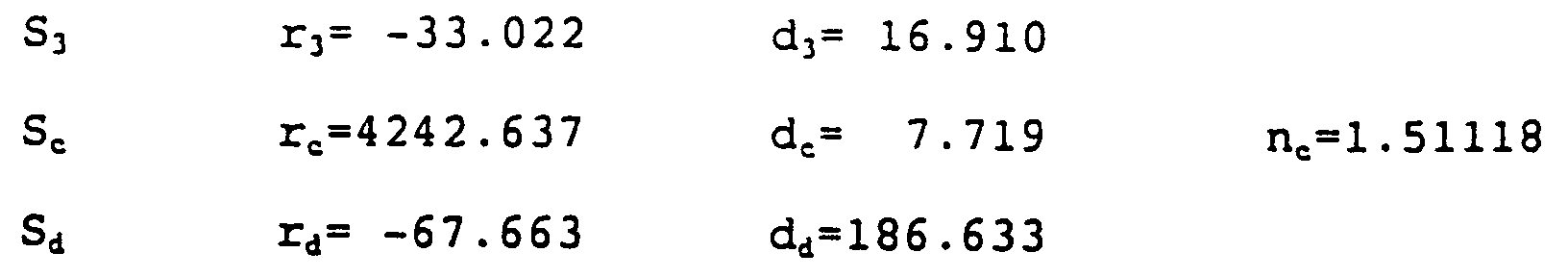
2ω = 40.0°Surface Radius of curvature Distance between faces Refractive index S₁ r₁= -32.377 d₁= 10.000 n₁=1.51118 S₂ r₂= ∞ d₂= 10.000 n₂=1.51118 S₃ r₃= -62.638 d₃= 14.373 Sc rc=-410.915 dc= 8.287 nc=1.51118 Sd rd= -46.642 dd=188.374 - In this design, the rotating center O of the
lens mirror 3 is on the side opposite the entrance face S₁ or the exit face S₃ with respect to the reflecting face S₂ and its position is 4.243 mm distant from the optical axis of the reflecting face S₂ in the normal direction. Figs. 32(a) and 32(b) are graphs plotting the aberrations that occur in the design of Example 12. - Fig. 33 shows a cross section of the beam scanning apparatus of Example 13 as it is taken in the main scanning direction. The drawing shows deliberately a light beam scanning at the scan center. In the apparatus of Example 13, a light beam from the
semiconductor laser 1 that has passed through thecollimator lens 2 is not parallel light but a slightly divergent beam is launched into thelens mirror 3. Hence, animaging lens 4 is inserted in the apparatus. - As in the case of Example 13, the light beam to be launched into the
lens mirror 3 need not be a completely collimated beam. If it is not absolutely necessary to produce a parallel light beam, there will be a greater latitude in optical design. - The optical specifications of a representative design for Example 13 are shown below:
2ω = 54.1°Surface Radius of curvature Distance between faces Refractive index S₀ d₀= 5.955 Sa ra= ∞ da= 2.000 na=1.51118 Sb rb= -4.089 db= 30.000 S₁ r₁= -19.667 d₁= 10.000 n₁=1.48261 S₂ r₂= ∞ d₂= 10.000 n₂=1.48261 S₃ r₃= -24.157 d₃= 15.552 Sc rc=-233.611 dc= 12.834 nc=1.51118 Sd rd= -42.622 dd=141.614 - Figs. 34(a) and 34(b) are graphs plotting the aberrations that occur in the design of Example 13.
- Fig. 35 shows a cross section of the beam scanning apparatus of Example 14 as it is taken in the main scanning direction. The drawing shows deliberately a light beam scanning at the scan center. In all of Examples 1 to 13,
collimator lens 2 is used for transforming the divergent light from thesemiconductor laser 1 into a parallel or near-parallel light beam. In contrast, the beam scanning apparatus of Example 14 does not use thecollimator lens 2 but is allows the light beam from thesemiconductor laser 1 to be directly launched into thelens mirror 3, with animaging lens 4 being inserted. - As will be clear from Fig. 36, Example 14 has the advantage that the number of optical components to be used is sufficiently reduced to lower the parts cost and that, in addition, a compact apparatus can be assembled and adjusted easily. The optical specifications of a representative design for Example 14 are shown below.
2ω = 40.2°Surface Radius of curvature Distance between faces Refractive index S₀ d₀= 6.000 S₁ r₁= 16.493 d₁= 10.000 n₁=1.48261 S₂ r₂= ∞ d₂= 10.000 n₂=1.48261 S₃ r₃= -10.099 d₃= 27.745 Sc rc=15779.220 dc= 8.606 nc=1.51118 Sd rd= -76.692 dd=156.617 - The first surface is aspheric and has the following aspheric coefficients:
K₁=-1.10820
A₁=-1.61596×10⁻⁴
B₁= 0 - Figs. 37(a) and 37(b) are graphs plotting the aberrations that occur in the design of Example 14.
- Fig. 38 is a drawing that shows the beam scanning apparatus of Example 15; Fig. 38(a) shows a cross section as taken in the main scanning direction and Fig. 38(b) is a cross section as taken in the sub-scanning direction and developed with respect to the reflecting face S₂.
- In this example, scanning quality at uniform speed is not considered and the apparatus is designed to correct only curvature of the field and astigmatism. The entrance face S₁ and exit face S₃ of the
lens mirror 3 are both toric and the apparatus is so adapted that a light beam collimated by thecollimator lens 2 is launched into thelens mirror 2. - As in this example, one need not consider the scanning quality at uniform speed and, instead, he may correct only curvature of the field and astigmatism. In this way, the two kinds of aberration can be corrected in a very efficient manner. For achieving high scanning quality at uniform speed, one may adopt any suitable method such as variable control over the clocking of a modulation signal to be supplied to the light source. The optical specifications of a representative design for Example 15 are shown below:
2ω = 22.9°Surface Radius of curvature Distance between faces Refractive index S₁ rx₁=19.732 d₁= 10.000 n₁=1.51118 ry₁=29.943 S₂ r₂= ∞ d₂= 10.000 n₂=1.51118 S₃ rx₃=14.733 d₃=211.207 ry₃=29.567 - Fig. 39 is a graph plotting the field curvature that occurs in the design of Example 15. Since the scanning quality at uniform speed is not considered in this example, no graph is given that depicts the scanning linearity.
- Fig. 40 shows a cross section of the beam scanning apparatus of Example 16 as it is taken in the sub-scanning direction. Fig. 41 is a perspective view of the same scanning apparatus. In this example, the angle formed between the optical axes of the entrance face S₁ and exit face S₃ of the
lens mirror 3 is zero through the cross section taken in the main scanning direction (i.e., the angle β shown in Fig. 6 is zero) where as it takes on some positive value through the cross section taken in the sub-scanning direction. A light beam issuing from thesemiconductor laser 1 is launched into thelens mirror 3 through the cross section in the main scanning direction as it is directed from the scan center of the scanning plane towards the rotating center of thelens mirror 3; the incident beam is reflected for deflection at a certain positive angle in the sub-scanning direction. The reflecting face S₂ of the lens mirrors 3 is spherical. The light beam to be launched into thelens mirror 3 has been collimated by thecollimator lens 2. - As in Example 16, the angle formed between the optical axes of the entrance face S₁ and exit face S₃ of the
lens mirror 3 may be adjusted to assume a certain positive value through the cross section taken in the sub-scanning direction while the angle is reduced to zero in the cross section taken in the main scanning direction. - As already mentioned in connection with Example 7, rendering the reflecting face S₂ of the
lens mirror 3 spherical offers the advantage of providing a higher degree of freedom in optical design and making it possible to correct the astigmatism that may occur in thesemiconductor laser 1 serving as the light source. On the other hand, however, the optical characteristics of the apparatus will become asymmetric with respect to the scan center and, hence, various aberrations cannot completely be corrected by means of axially symmetric optics alone that are represented by the spherical lens. However, if, as in Example 16, the angle formed between the optical axes of the entrance face S₁ and exit face S₃ of thelens mirror 3 is adjusted to zero in the cross section taken in the main scanning direction so that the incident light beam will be launched into thelens mirror 3 through the cross section in the main scanning direction as it is directed from the scan center of the scanning plane towards the rotating center of thelens mirror 3, the optical characteristics of the apparatus will be symmetric with respect to the scan center even if the reflecting face S₂ is spherical; hence, it becomes possible to correct various aberrations by using only axially symmetric optics. - If, as in Example 1, the plane formed by the optical axes of the entrance face S₁ and exit face S₃ of the
lens mirror 3 coincides with the plane of deflection which is formed by the deflected light beam, the aperture diameter of the entrance face S₁ is limited by its position relative to the exit face S₃; furthermore, as already explained with reference to Fig. 27(a), the angle through which thelens mirror 3 is rotated in association with the scan region is limited by the aperture diameter of the entrance face S₁. However, in Example 16, the entrance face S₁ and the exit face S₃ extend in different planes, one being directed upward and the other downward, as shown in Fig. 41; therefore, there is no limitation by the aperture diameter of the entrance face S₁. - Another feature of the apparatus of Example 16 is that the optics comprising the
semiconductor laser 1,collimator lens 2 and thelens mirror 3 can be brought close to the region wherein the light beam deflected by thelens mirror 3 will pass, thus contributing compactness to the overall size of the apparatus. The optical specifications of a representative design for Example 16 are shown below:
2ω = 34.0°Surface Radius of curvature Distance between faces Refractive index S₁ r₁= - 5.853 d₁= 15.000 n₁=1.48261 S₂ r₂=176162.811 d₂= 15.000 n₂=1.48261 S₃ r₃= -13.964 d₃=235.000 - The first and third faces are aspheric having the following aspheric coefficients:
K₁=-0.50391
A₁= 5.97781×10⁻⁵
B₁=-1.54233×10⁻⁶
K₃=-0.55676
A₃=-1.08363×10⁻⁶
B₃= 0 - It should also be noted that the optical axes of the entrance face S₁ and exit face S₃ of the
lens mirror 3 form an angle of 30° through the cross taken as taken in the sub-scanning direction. - Figs. 42(a) and 42(b) are graphs plotting the aberrations that occur in the design of Example 16.
- Fig. 43 shows a cross section of the beam scanning apparatus of Example 17 as it is taken in the main scanning direction. Fig. 44 is a perspective view of the same apparatus. The apparatus of Example 17 is so designed that a light beam issuing from the
lens mirror 3 is reflected by the reflecting face Se of abending mirror 7 so that it is focused on the scanning plane. Thebending mirror 7 has a concave surface and is positioned in such a way that a light beam passing through the scan center is bent back by 180°. A light beam collimated by thecollimator lens 2 is launched into thelens mirror 3. - As in Example 17, not only lenses but also a spherical mirror may be employed to correct aberrations. Beam scanning apparatus, particularly one that is used with a laser printer, often use a bending mirror for changing the direction of a travelling light beam; if the bending mirror is adapted to have a spherical surface so that it is provided with a power, the various aberrations that will develop in the apparatus can be reduced without increasing the number of components to be used. In the case of Example 17, the light beam on the optical axis is bent back by 180°, so in order to direct the light beam toward the scanning plane, one may employed a half mirror 8 or the like. Alternatively, the bending mirror may be inclined in the sub-scanning direction so as to direct the beam of reflected light towards the scanning plane. The optical specifications of a representative design for Example 17 are shown below:
2ω = 45.4°Surface Radius of curvature Distance between faces Refractive index S₁ r₁= -46.185 d₁= 10.000 n₁=1.51118 S₂ r₂= ∞ d₂= 10.000 n₂=1.51118 S₃ r₃= -36.642 d₃=110.000 Se re=-358.056 de= 73.088 - Figs. 45(a) and 45(b) are graphs plotting the aberrations that occur in the design of Example 17.
- All of the above-described examples refer to the case where the
lens mirror 3 rotates at uniform speed. It should, however, be noted that those examples can easily be implemented for the case where the lens mirror makes sinusoidal vibrations around the rotating shaft. The specific designs of those examples are intended for operation at specified wavelengths; it should, however, be noted that with slight modifications, equally good results can be attained for light beams within ir, uv, X-ray and other wavelength regions including the visible range. - As described on the foregoing pages, the beam scanning apparatus of a specific aspect of the present invention is characterized in that a single optical element is provided with not only a reflecting face but also an entrance face and an exit face that are specified for shape in such a way as to effect predetermined correction of aberrations. As a result, it becomes possible to deflect a light beam for scanning purposes by the optical element per se, thus permitting a substantial reduction in the number of expensive optical parts to be employed. Furthermore, even in the case of using an imaging lens as an auxiliary component, a lens of a smaller aperture can be used with the conventional beam scanning apparatus while, at the same time, it becomes possible to use inexpensive optical materials of low refractive index. Hence, beam scanning apparatus of the type contemplated by the invention which are to be applied to image forming systems such as laser printer, digital copier, facsimile and laser scanning display, or an image input device such as scanner, or optical mark reading laser scanner or surface detecting laser scanner can be provided in small size and at low cost.
- In addition, when assembling or adjusting the optics in those systems, the smallness of the number of parts reduces the required volume of work, thereby contributing to a marked improvement in the operational efficiency.
Claims (16)
- A beam scanning apparatus in which a reflecting face (S₂), as well as an entrance face (S₁) and an exit face (S₃), at least one of which is so specified for shape as to be capable of correcting aberrations, are provided for an optical element (3) that is driven by a rotational drive means to rotate and deflects a beam from a beam generator (1).
- A beam scanning apparatus according to claim 1 wherein said entrance face (S₁) is made concave whereas said exit face (S₃) is made convex.
- A beam scanning apparatus according to claim 1 wherein said entrance face (S₁) is made convex whereas said exit face (S₃) is made concave.
- A beam scanning apparatus according to claim 1 wherein either at least one of said entrance face (S₁) and said exit face (S₃) is made planar.
- A beam scanning apparatus according to any one of the preceding claims wherein at least one of said entrance face (S₁) and said exit face (S₃) is made aspheric.
- A beam scanning apparatus according to claim 1 wherein at least one of said entrance face (S₁) and said exit face (S₃) is made toric.
- A beam scanning apparatus according to any one of the preceding claims which is so adapted that the radii of curvature of said entrance and exit faces satisfy the following equation:

- A beam scanning apparatus according to any one of the preceding claims wherein the rotating axis (0) of said optical element (3) is included in said reflecting face (S₂).
- A beam scanning apparatus according to any one of claims 1 to 7 wherein the rotating axis (0) of said optical element (3) is positioned in the interior of the latter.
- A beam scanning apparatus according to any one of claims 1 to 7 wherein the rotating axis (0) of said optical element (3) is positioned on the side opposite said entrance and exit faces (S₁, S₃) with respect to said reflecting face (S₂).
- A beam scanning apparatus according to any one of the preceding claims wherein the optical axis of said entrance face (S₁) is made different from the optical axis of said exit face (S₃) in a cross section taken in the sub-scanning direction.
- A beam scanning apparatus according to any one of the preceding claims wherein said optical element (3) is adapted to correct only the curvature of field and astigmatism.
- A beam scanning apparatus according to any one of the preceding claims which further includes imaging optics (4, 7) to insure that a beam deflected by said optical element (3) is focused on an imaging plane.
- A beam scanning apparatus according to claim 13 wherein said imaging optics is a reflecting mirror (7) having a curved reflecting surface.
- A beam scanning apparatus according to claim 13 wherein said imaging optics is a single lens (4).
- A beam scanning apparatus according to claim 15 wherein said single lens (4) has a positive refractive power.
Applications Claiming Priority (4)
| Application Number | Priority Date | Filing Date | Title |
|---|---|---|---|
| JP16604292 | 1992-06-24 | ||
| JP166042/92 | 1992-06-24 | ||
| JP121995/93 | 1993-04-26 | ||
| JP05121995A JP3134906B2 (en) | 1992-06-24 | 1993-04-26 | Beam scanning device |
Publications (3)
| Publication Number | Publication Date |
|---|---|
| EP0576014A2 true EP0576014A2 (en) | 1993-12-29 |
| EP0576014A3 EP0576014A3 (en) | 1994-11-02 |
| EP0576014B1 EP0576014B1 (en) | 1999-03-24 |
Family
ID=26459225
Family Applications (1)
| Application Number | Title | Priority Date | Filing Date |
|---|---|---|---|
| EP93110128A Expired - Lifetime EP0576014B1 (en) | 1992-06-24 | 1993-06-24 | Beam scanning apparatus |
Country Status (4)
| Country | Link |
|---|---|
| US (1) | US5528279A (en) |
| EP (1) | EP0576014B1 (en) |
| JP (1) | JP3134906B2 (en) |
| DE (1) | DE69324070T2 (en) |
Cited By (4)
| Publication number | Priority date | Publication date | Assignee | Title |
|---|---|---|---|---|
| EP0629891A1 (en) * | 1993-06-18 | 1994-12-21 | Seiko Epson Corporation | Beam scanning apparatus |
| FR2731083A1 (en) * | 1995-02-23 | 1996-08-30 | Seiko Epson Corp | OPTICAL SCANNING DEVICE |
| WO2001025832A3 (en) * | 1999-10-07 | 2001-12-13 | Raytheon Co | Ultra-wide field of view concentric scanning sensor system |
| EP1450558A1 (en) * | 2003-02-18 | 2004-08-25 | Canon Kabushiki Kaisha | Scan type display |
Families Citing this family (4)
| Publication number | Priority date | Publication date | Assignee | Title |
|---|---|---|---|---|
| US6867916B2 (en) * | 1995-01-11 | 2005-03-15 | Canon Kabushiki Kaisha | Viewfinder optical system |
| JP2009145897A (en) * | 1995-02-28 | 2009-07-02 | Canon Inc | Scanning optical device and laser beam printer having the same |
| US7324132B2 (en) * | 2003-05-06 | 2008-01-29 | Hewlett-Packard Development Company, L.P. | Imaging three-dimensional objects |
| JP7647151B2 (en) * | 2021-02-19 | 2025-03-18 | 株式会社リコー | Optical scanning device, object detection device, sensing device and moving body |
Family Cites Families (8)
| Publication number | Priority date | Publication date | Assignee | Title |
|---|---|---|---|---|
| GB343112A (en) * | 1929-10-12 | 1931-02-12 | William Ewart Williams | Improvements in optical vibration-recording apparatus |
| DE1100315B (en) * | 1958-10-23 | 1961-02-23 | Wonder Piles | Mirror prism with curved surfaces, especially for use in a hand lamp |
| GB1290144A (en) * | 1968-12-24 | 1972-09-20 | ||
| US3614194A (en) * | 1969-06-27 | 1971-10-19 | Te Co The | Wide field optical scanner |
| US4061415A (en) * | 1976-07-02 | 1977-12-06 | Sanford Research Institute | Nutating radiation deflecting method and apparatus |
| US4514050A (en) * | 1982-07-22 | 1985-04-30 | Bell & Howell Company | Dove prism for convergent light paths |
| JPH04200070A (en) * | 1990-11-29 | 1992-07-21 | Sharp Corp | Image forming method |
| DE4130977C2 (en) * | 1991-09-18 | 1994-05-19 | Hell Ag Linotype | Beam deflector |
-
1993
- 1993-04-26 JP JP05121995A patent/JP3134906B2/en not_active Expired - Fee Related
- 1993-06-23 US US08/079,827 patent/US5528279A/en not_active Expired - Lifetime
- 1993-06-24 EP EP93110128A patent/EP0576014B1/en not_active Expired - Lifetime
- 1993-06-24 DE DE69324070T patent/DE69324070T2/en not_active Expired - Fee Related
Cited By (7)
| Publication number | Priority date | Publication date | Assignee | Title |
|---|---|---|---|---|
| EP0629891A1 (en) * | 1993-06-18 | 1994-12-21 | Seiko Epson Corporation | Beam scanning apparatus |
| US5771062A (en) * | 1993-06-18 | 1998-06-23 | Seiko Epson Corporation | Beam scanning apparatus, for providing tilt correction to a rotary optical device |
| EP0813087A3 (en) * | 1993-06-18 | 1998-10-14 | Seiko Epson Corporation | Beam scanning apparatus |
| FR2731083A1 (en) * | 1995-02-23 | 1996-08-30 | Seiko Epson Corp | OPTICAL SCANNING DEVICE |
| WO2001025832A3 (en) * | 1999-10-07 | 2001-12-13 | Raytheon Co | Ultra-wide field of view concentric scanning sensor system |
| EP1450558A1 (en) * | 2003-02-18 | 2004-08-25 | Canon Kabushiki Kaisha | Scan type display |
| US7264360B2 (en) | 2003-02-18 | 2007-09-04 | Canon Kabushiki Kaisha | Scan type display optical system |
Also Published As
| Publication number | Publication date |
|---|---|
| EP0576014B1 (en) | 1999-03-24 |
| DE69324070T2 (en) | 1999-11-18 |
| JPH0675162A (en) | 1994-03-18 |
| EP0576014A3 (en) | 1994-11-02 |
| US5528279A (en) | 1996-06-18 |
| DE69324070D1 (en) | 1999-04-29 |
| JP3134906B2 (en) | 2001-02-13 |
Similar Documents
| Publication | Publication Date | Title |
|---|---|---|
| EP0827004B1 (en) | Corrected scanning optical apparatus | |
| US4179183A (en) | Device for scanning a light beam at a constant speed | |
| EP0730182B1 (en) | Scanning optical apparatus | |
| EP0853253B1 (en) | Optical scanning apparatus | |
| EP0851262A2 (en) | Scanning optical apparatus | |
| US5973813A (en) | Reflection type optical scanning system | |
| US5179465A (en) | Optical system for light beam scanning | |
| US4850663A (en) | Light scanning system | |
| US20010043409A1 (en) | Collimator lens and optical scanning apparatus using the same | |
| JP3117524B2 (en) | Scanning optical system with surface tilt correction function | |
| US5812181A (en) | Scanning optical apparatus | |
| EP0576014A2 (en) | Beam scanning apparatus | |
| US6215574B1 (en) | Scanning optical device and multi-beam scanning optical device | |
| EP0813087B1 (en) | Beam scanning apparatus | |
| EP0857991B1 (en) | Scanning optical system | |
| US6927883B1 (en) | Light-scanning optical apparatus and image forming apparatus | |
| JP3215764B2 (en) | Reflective scanning optical system | |
| US6670980B1 (en) | Light-scanning optical system | |
| JP3121452B2 (en) | Optical scanning device | |
| US5768028A (en) | Scanning optics | |
| JP3472205B2 (en) | Optical scanning optical device and image forming apparatus using the same | |
| JP3420439B2 (en) | Optical scanning optical system and laser beam printer including the same | |
| US5673137A (en) | Condenser optical system for light scanning system | |
| US6178030B1 (en) | Light-scanning optical system having wobble-correcting function and light-scanning apparatus using the same | |
| JP3320239B2 (en) | Scanning optical device |
Legal Events
| Date | Code | Title | Description |
|---|---|---|---|
| PUAI | Public reference made under article 153(3) epc to a published international application that has entered the european phase |
Free format text: ORIGINAL CODE: 0009012 |
|
| AK | Designated contracting states |
Kind code of ref document: A2 Designated state(s): DE FR GB |
|
| PUAL | Search report despatched |
Free format text: ORIGINAL CODE: 0009013 |
|
| AK | Designated contracting states |
Kind code of ref document: A3 Designated state(s): DE FR GB |
|
| 17P | Request for examination filed |
Effective date: 19950502 |
|
| RIN1 | Information on inventor provided before grant (corrected) |
Inventor name: TAKADA, KYU Inventor name: INOUE, NOZOMU Inventor name: NOMURA, YUJIRO Inventor name: SUZUKI, TAKASHI |
|
| 17Q | First examination report despatched |
Effective date: 19970130 |
|
| GRAG | Despatch of communication of intention to grant |
Free format text: ORIGINAL CODE: EPIDOS AGRA |
|
| GRAG | Despatch of communication of intention to grant |
Free format text: ORIGINAL CODE: EPIDOS AGRA |
|
| GRAH | Despatch of communication of intention to grant a patent |
Free format text: ORIGINAL CODE: EPIDOS IGRA |
|
| GRAH | Despatch of communication of intention to grant a patent |
Free format text: ORIGINAL CODE: EPIDOS IGRA |
|
| GRAA | (expected) grant |
Free format text: ORIGINAL CODE: 0009210 |
|
| AK | Designated contracting states |
Kind code of ref document: B1 Designated state(s): DE FR GB |
|
| REF | Corresponds to: |
Ref document number: 69324070 Country of ref document: DE Date of ref document: 19990429 |
|
| ET | Fr: translation filed | ||
| PLBE | No opposition filed within time limit |
Free format text: ORIGINAL CODE: 0009261 |
|
| STAA | Information on the status of an ep patent application or granted ep patent |
Free format text: STATUS: NO OPPOSITION FILED WITHIN TIME LIMIT |
|
| 26N | No opposition filed | ||
| REG | Reference to a national code |
Ref country code: GB Ref legal event code: IF02 |
|
| PGFP | Annual fee paid to national office [announced via postgrant information from national office to epo] |
Ref country code: DE Payment date: 20070621 Year of fee payment: 15 |
|
| PGFP | Annual fee paid to national office [announced via postgrant information from national office to epo] |
Ref country code: GB Payment date: 20070620 Year of fee payment: 15 |
|
| PGFP | Annual fee paid to national office [announced via postgrant information from national office to epo] |
Ref country code: FR Payment date: 20070608 Year of fee payment: 15 |
|
| GBPC | Gb: european patent ceased through non-payment of renewal fee |
Effective date: 20080624 |
|
| REG | Reference to a national code |
Ref country code: FR Ref legal event code: ST Effective date: 20090228 |
|
| PG25 | Lapsed in a contracting state [announced via postgrant information from national office to epo] |
Ref country code: DE Free format text: LAPSE BECAUSE OF NON-PAYMENT OF DUE FEES Effective date: 20090101 |
|
| PG25 | Lapsed in a contracting state [announced via postgrant information from national office to epo] |
Ref country code: GB Free format text: LAPSE BECAUSE OF NON-PAYMENT OF DUE FEES Effective date: 20080624 |
|
| PG25 | Lapsed in a contracting state [announced via postgrant information from national office to epo] |
Ref country code: FR Free format text: LAPSE BECAUSE OF NON-PAYMENT OF DUE FEES Effective date: 20080630 |