EP0576190A1 - Chromplattiertes Motorventil - Google Patents
Chromplattiertes Motorventil Download PDFInfo
- Publication number
- EP0576190A1 EP0576190A1 EP93304634A EP93304634A EP0576190A1 EP 0576190 A1 EP0576190 A1 EP 0576190A1 EP 93304634 A EP93304634 A EP 93304634A EP 93304634 A EP93304634 A EP 93304634A EP 0576190 A1 EP0576190 A1 EP 0576190A1
- Authority
- EP
- European Patent Office
- Prior art keywords
- chromium
- valve
- stem
- coating
- solution
- Prior art date
- Legal status (The legal status is an assumption and is not a legal conclusion. Google has not performed a legal analysis and makes no representation as to the accuracy of the status listed.)
- Withdrawn
Links
Images

Classifications
-
- C—CHEMISTRY; METALLURGY
- C25—ELECTROLYTIC OR ELECTROPHORETIC PROCESSES; APPARATUS THEREFOR
- C25D—PROCESSES FOR THE ELECTROLYTIC OR ELECTROPHORETIC PRODUCTION OF COATINGS; ELECTROFORMING; APPARATUS THEREFOR
- C25D3/00—Electroplating: Baths therefor
- C25D3/02—Electroplating: Baths therefor from solutions
- C25D3/04—Electroplating: Baths therefor from solutions of chromium
- C25D3/06—Electroplating: Baths therefor from solutions of chromium from solutions of trivalent chromium
-
- C—CHEMISTRY; METALLURGY
- C25—ELECTROLYTIC OR ELECTROPHORETIC PROCESSES; APPARATUS THEREFOR
- C25D—PROCESSES FOR THE ELECTROLYTIC OR ELECTROPHORETIC PRODUCTION OF COATINGS; ELECTROFORMING; APPARATUS THEREFOR
- C25D5/00—Electroplating characterised by the process; Pretreatment or after-treatment of workpieces
- C25D5/48—After-treatment of electroplated surfaces
- C25D5/50—After-treatment of electroplated surfaces by heat-treatment
-
- F—MECHANICAL ENGINEERING; LIGHTING; HEATING; WEAPONS; BLASTING
- F01—MACHINES OR ENGINES IN GENERAL; ENGINE PLANTS IN GENERAL; STEAM ENGINES
- F01L—CYCLICALLY OPERATING VALVES FOR MACHINES OR ENGINES
- F01L3/00—Lift-valve, i.e. cut-off apparatus with closure members having at least a component of their opening and closing motion perpendicular to the closing faces; Parts or accessories thereof
- F01L3/02—Selecting particular materials for valve-members or valve-seats; Valve-members or valve-seats composed of two or more materials
- F01L3/04—Coated valve members or valve-seats
-
- F—MECHANICAL ENGINEERING; LIGHTING; HEATING; WEAPONS; BLASTING
- F02—COMBUSTION ENGINES; HOT-GAS OR COMBUSTION-PRODUCT ENGINE PLANTS
- F02B—INTERNAL-COMBUSTION PISTON ENGINES; COMBUSTION ENGINES IN GENERAL
- F02B3/00—Engines characterised by air compression and subsequent fuel addition
- F02B3/06—Engines characterised by air compression and subsequent fuel addition with compression ignition
Definitions
- This invention relates generally to an internal combustion engine valve having a wear resistant plating or coating of chromium thereon and more particularly to an engine valve whose stem has been provided with a wear resistant chromium coating that has been electrodeposited from an aqueous solution containing trivalent chromium and then heated at a temperature of at least about 150°F for at least about thirty minutes to create a complex chromium carbide compound with an admixture of chromium oxides to establish a highly effective bond therebetween as well as to substantially lengthen the time to seizure under simulated operating conditions over that for hexavalent chromium plating heretofor used for such purpose.
- the stems of internal combustion engine valves are required to reciprocate at high speed and at high temperatures within valve guides while the engine is operating as well as being subjected to bending forces arising from improper seating and/or rocker arm side loads and other conditions of misalignment that in general render the stems susceptible to frictional wear which is even further aggravated under the current trend to increased engine speeds and operating temperatures and decreased availability of lubrication at the valve's stem.
- valve stems are generally protected by various methods, chromium plating has been most commonly used to achieve wear durability and improve performance of valve stem motion within the valve guide which acts as a linear bearing and therefore is itself subject to wear by reason of its ultimate contact with the valve stem.
- Seizure or sticking of the valve stem in the valve guide is perhaps an even more common mode of stem-guide interference failure than an increase in clearance between the stem and the guide arising from wear for it characteristically results in the valve being seized in the open position which may be followed by combustion chamber leakage and possibly valve breakage in the event the engine piston hits the valve head while the stem is seized in the open position.
- Chromium is a generally an abundant element in the earth's crust and occurs in oxidated states ranging from Cr+2 (divalent) to Cr6+ (hexavalent).
- hexavalent chromium could provide an effective wear resistant surface for internal combustion engine valves for it bonded well to the metallic stem substrate and, even though hexavalent and trivalent chromium exhibit similar as deposited characteristics as a coating, trivalent chromium up until the present invention has not exhibited sufficient hardness or adherance of the coating to the valve stem to withstand the rigors of high speed and high temperature engine operation.
- Electrodepositing chromium coatings from a bath containing hexavalent chromium ions are disclosed in United States Patents 3,930,527 and 4,108,770, the disclosures of which are incorporated herein by reference.
- the present invention involves converting the engine valve industry from the historical practice of electroplating valve stems with hexavalent chromium ions to electroplating the stems with trivalent chromium ions that heretofor were unable to adhere to the stem sufficiently to withstand the rigors of engine operation and have now been found to be even superior to hexavalent chromium in resisting seizure due to exceptional hardness developed by post-plating heat treatment.
- hexavalent chromium and its compounds are known as carcinogens and, as yet, no evidence has been observed for the carcinogenic effects of trivalent chromium on laboratory animals unlike hexavalent chromium according to ACGIH publication, Sixth Edition (1991) entitled "DOCUMENTATION OF THRESHOLD LIMIT VALUES AND BIOLOGICAL EXPOSURE INDICES".
- an object of this invention to provide an internal combustion engine valve whose stem has a trivalent chromium coating thereon that is highly resistant to wear.
- FIGURE 1 illustrates a typical arrangement for mounting a valve 100 such as a poppet valve for reciprocal movement of its stem 4 within a valve guide 18 in an engine block 14.
- Valve 100 is a metallic valve made from one or more metals selected according to whether valve 100 is an intake or an exhaust valve as is well known to those skilled in engine valve art.
- the most common intake valve stem material is a low alloy of hardened and tempered martensitic steel such as SAE 1547 or 8645.
- a high chromium martensitic steel sold under the trademark Silchrome 1 is known to be widely used for engine valve stems in Europe.
- the most common exhaust valve material is an austenitic stainless steel strengthened by carbides and nitrides.
- Nickel base super alloys have also been used in some applications such as in heavy duty diesel engines. In some exhaust valves, it has been the practice to employ two different metals such as where the head referenced by numeral 2 in FIGURE 1 is made from austenitic or a nickel based alloy and the stem 4 is made from a low alloy steel.
- Head 2 of valve 100 of FIGURE 1 has an annular valve seat 22 thereabout that engages a valve seat insert 20 that is secured within an opening extending through engine block 14 to the engine combustion chamber.
- Valve seat 22 and insert 20 are made from hardened and high temperature and wear resistant materials well known to those skilled in the art.
- Stem 4 of valve 100 extends through a valve stem guide 18 secured in the opening through engine block 14 and is operative to move reciprocally relative thereto. Typical diametral clearance between an engine valve stem and the stem guide is from about .0008 inch to about .0030 inch.
- the most common guide valve stem material is annealed pearlitic cast iron.
- the cast iron guides are inserted in the cylinder heads and reamed in place concentric with the valve seat prior to assembly, in order to ensure valve alignment.
- Powdered metal (P/M) steel guides are currently finding increasing applications throughout the world. P/M guides are made by pressing and sintering iron powder with suitable alloy elements.
- the graphite present in the microstructure of the cast iron provides added wear protection in the form of a solid lubricant. While the P/M guide acts much like an oil impregnated bearing for wear prevention, solid lubricant additions, such as talc, have been known to provide significant additional wear protection.
- Stem 4 includes an annular keeper groove 8 at its opposite end adjacent its tip end 6.
- a retainer 10 is secured in groove 8 and holds a valve spring 12 under compression between retainer 10 and engine block 14.
- a valve stem seal 16 is preferably secured to the side of the engine block facing away from the combustion chamber to prevent lubricants from entering the combustion chamber.
- the presence of an engine oil film at the valve guide/stem interface by the leakage of engine oil from the top of the guide provides protection from adhesive wear.
- tighter oil seals are being used to cap the valve guides in the current engines. The trend has resulted in an increase in the incidents of valve stem guide seizure in many engine systems. The trend toward tighter valve stem seals is expected to continue in the future, demanding better valve stem wear protection systems.
- Spring 12 is commonly a coiled spring that operates to urge seat 22 of valve head 2 against insert 20 (upwardly in FIGURE 1) to provide a closed condition after it has been moved to its open condition by means of a rotary cam or rocker arm driven by the engine that presses tip 6 of valve 100 downwardly to the open position which is not shown in FIGURE 1.
- FIGURE 2 illustrates an embodiment of the method of the invention by which the stem of valve 100 is electroplated with trivalent chromium and then heat treated or aged to provide a chromium coating on the stem that is well adhered and surprisingly exhibits a resistance to seizure that is markedly superior to that exhibited by hexavalent chromium.
- step (a) of FIGURE 1 the stem of valve 100 is immersed in an aqueous electroplating solution 26 contained in a bath 24.
- aqueous electroplating solution 26 contained in a bath 24.
- electrolyte solutions for electroplating onto metal and other substrates from a solution containing trivalent chromium ions the following electrolyte solution, temperature, and electrical current conditions, have been found to provide an effective uniform plating on metallic engine valve stems.
- the electrolyte solution used in the method of the invention is preferably the type sold by M&T Chemical Company under the trademark TRICHROME the comprises an aqueous mixture of trivalent chromium ions and boric acid and is preferably heated to a bath temperature of about 110°F to about 120°F. More specifically, the solution preferably contains from about 20 to about 25 and more preferably to about 23 grams of trivalent chromium ions and from about 60 to about 65 grams of boric acid per liter of the solution to provide a pH that is about 2 to 3 and more preferably from about 2.3 to about 2.7 and a specific gravity of about 1.20 to about 1.30 and more preferably from about 1.22 to about 1.26.
- the above described electrolyte solution preferably further includes at least one stabilizer of which exlempary examples are citric acid, formic acid, and sodium formate that is used to keep all ionic chromium in the +3 valence state and which is preferably added in the amount of about 65 to about 75 milliters per liter of the electrolyte solution.
- the above described electrolyte solution also further preferably includes a regulator of which exemplary examples are chromium III sulfate or a mixture of chromium III sulfate-chloride and conducting salts and of which the preferred example is the latter which is used to control the Cr+3 ionic concentration of the electrolyte and the bulk electrical conductivity and which is added in the amount of from about 2 to about 4 milliters per liter of the electrolyte solution which is preferably agitated during the plating process such as by an air motor stirrer blade or other suitable agitator.
- a regulator of which exemplary examples are chromium III sulfate or a mixture of chromium III sulfate-chloride and conducting salts and of which the preferred example is the latter which is used to control the Cr+3 ionic concentration of the electrolyte and the bulk electrical conductivity and which is added in the amount of from about 2 to about 4 milliters per liter of the electrolyte solution which is preferably
- a suitable electrical power source such as a 6 to 12 volt rectifier 28 is connected between an anode (such as a graphite or a graphite composite) with engine valve 100 acting as the cathode.
- anode such as a graphite or a graphite composite
- the battery generated direct current is preferably a steady electrical current, it may be pulsed as is a well known practice in the electroplating art.
- the electrical potential between the cathode and anode as such as to provide an electrical current density of from about 100 to about 150 amps per square foot of stem surface immersed in the solution and more preferably from about 110 to about 140 amps per square foot of stem surface immersed in the solution.
- a time period of about 4 minutes in the above described electroplating solution will provide a substantially uniform coating of chromium on the valve stem having a thickness of about .00008 inch average.
- step (a) The coated valve of step (a) is then removed from the electroplating solution, rinsed free of electroyte, and dried and then heated in step (b) in an oven referenced by numeral 30 at a temperature of at least about 150°F for a time period of at least about 30 minutes in air or in suitable inert atmosphere such as an argan or nitrogen atmosphere.
- step (b) creates a covalent bond between the chromium ions and carbon ions present in the trivalent chromium coating resulting in the formation of a chromium carbide bonding mechanism between the substrate and the chromium coating. It is also believed that various levels of oxidation may also occur converting the chromium ions to one or more (Cr x O y ) oxides of chromium which would tend to raise the hardness level of the chromium coating, particularly at elevated temperatures, and that both Cr x Cy and cr x O y compounds would generate extreme hardness sites withing the deposited coating, adding to the composite hardness observed.
- a simulation test rig 50 developed for the evaluation of the seizure characteristics of valve stems and guides is shown in FIGURE 3. It consists of a portion of valve stem 32 heated at the bottom end by a cartridge heater 40 to simulate the hot end of the stem and then coupled to control and measure the stem end temperature. Stem 32 is translated in guide 34 by a hydraulic actuator 44 of a MTS Hydraulic Testing machine. Guide 34 is inserted in a controlled temperature water cooled head 36. The hot end of guide 34 is brought up to the desired simulated temperature by an O.D. coil heater 38 at the bottom of the guide.
- Valve stem 32 is subjected to a selected sideload generated by dead weight 48 through a movement arm and measured by load cell 47 by means of a roller follower.
- the valve stem is pushed down by actuator 44 against a compression return spring in each cycle.
- the stem motion is monitored by a proximity probe 46 which indicates the seizure as a low limit or zero output.
- Stem motion ceases when the return spring 42 can no longer overcome the stem friction in the guide as a result of the wear process.
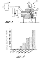
- the number of hours run prior to seizure can be determined and compared for various stem guide combinations in FIGURE 4.
- FIGURE 4 presents a comparison of the seizure times observed in rig test 50 for a 2l-2N austenitic steel valve stem.
- the temperature and load conditions for the test are listed in Table I.
- Untreated stems and stems with various coatings indicated in FIGURE 4 are described in Table II and were tested against cast iron and P/M steel guides.
- the seizure life of a trivalent chromium coated valve stem exceeds its closest rival (ion plasma nitride) by about 25 hours and hexavalent chromium coated stem (PM/Cr-P) by about 28 hours or, as otherwise expressed, exhibits a seizure life of about 1.8 times that for hexavalent chromium.
Landscapes
- Chemical & Material Sciences (AREA)
- Engineering & Computer Science (AREA)
- Chemical Kinetics & Catalysis (AREA)
- Electrochemistry (AREA)
- Materials Engineering (AREA)
- Metallurgy (AREA)
- Organic Chemistry (AREA)
- Mechanical Engineering (AREA)
- General Engineering & Computer Science (AREA)
- Electroplating Methods And Accessories (AREA)
- Electroplating And Plating Baths Therefor (AREA)
Applications Claiming Priority (2)
| Application Number | Priority Date | Filing Date | Title |
|---|---|---|---|
| US899966 | 1992-06-17 | ||
| US07/899,966 US5271823A (en) | 1992-06-17 | 1992-06-17 | Method of making a trivalent chromium plated engine valve |
Publications (1)
| Publication Number | Publication Date |
|---|---|
| EP0576190A1 true EP0576190A1 (de) | 1993-12-29 |
Family
ID=25411788
Family Applications (1)
| Application Number | Title | Priority Date | Filing Date |
|---|---|---|---|
| EP93304634A Withdrawn EP0576190A1 (de) | 1992-06-17 | 1993-06-15 | Chromplattiertes Motorventil |
Country Status (3)
| Country | Link |
|---|---|
| US (1) | US5271823A (de) |
| EP (1) | EP0576190A1 (de) |
| JP (1) | JPH0657478A (de) |
Cited By (3)
| Publication number | Priority date | Publication date | Assignee | Title |
|---|---|---|---|---|
| EP1391538A3 (de) * | 2002-08-19 | 2006-10-18 | TRW Automotive U.S. LLC | Chromplattiertes Motorventil |
| WO2009056239A1 (de) * | 2007-11-02 | 2009-05-07 | Märkisches Werk GmbH | Ein- oder auslassventil für einen verbrennungsmotor sowie verfahren zu dessen herstellung |
| DE102019129128A1 (de) * | 2019-10-29 | 2021-04-29 | Federal-Mogul Valvetrain Gmbh | Motorventil |
Families Citing this family (19)
| Publication number | Priority date | Publication date | Assignee | Title |
|---|---|---|---|---|
| DE19523915A1 (de) * | 1995-06-30 | 1997-01-02 | Bosch Gmbh Robert | Mikroventil und Verfahren zur Herstellung eines Mikroventils |
| EP1146137A1 (de) * | 1999-11-10 | 2001-10-17 | Cemm Co., Ltd | Verfahren zum nitrieren eines legierungsmaterials auf der basis aus der eisengruppe |
| US6599345B2 (en) | 2001-10-02 | 2003-07-29 | Eaton Corporation | Powder metal valve guide |
| US20030064158A1 (en) * | 2001-10-03 | 2003-04-03 | Thirkeldsen C. G. | Method and apparatus for improving corrosion resistance of chrome plated material |
| US6808751B2 (en) * | 2001-10-03 | 2004-10-26 | Industrial Hard Chrome | Method for improving corrosion resistance of chrome plated material |
| US7051961B2 (en) | 2002-06-07 | 2006-05-30 | Synerject, Llc | Fuel injector with a coating |
| US6676724B1 (en) | 2002-06-27 | 2004-01-13 | Eaton Corporation | Powder metal valve seat insert |
| US7144637B2 (en) * | 2004-07-12 | 2006-12-05 | Thomae Kurt J | Multilayer, corrosion-resistant finish and method |
| US7213586B2 (en) * | 2004-08-12 | 2007-05-08 | Borgwarner Inc. | Exhaust gas recirculation valve |
| US7159801B2 (en) * | 2004-12-13 | 2007-01-09 | Synerject, Llc | Fuel injector assembly and poppet |
| DE102008061237A1 (de) * | 2008-12-09 | 2010-06-10 | Man Diesel Se | Gaswechselventil und Verfahren zu seiner Herstellung |
| SE533842C2 (sv) * | 2009-06-16 | 2011-02-01 | Scania Cv Ab | Motorkomponent innefattande korrosionsskyddande skikt samt metod för tillverkning av motorkomponent |
| WO2014111616A1 (en) | 2013-01-15 | 2014-07-24 | Savroc Ltd | Method for producing a chromium coating on a metal substrate |
| BR112016016106B1 (pt) | 2014-01-15 | 2023-04-04 | Savroc Ltd | Método para produção de um revestimento de cromo sobre um objeto por trivalente cromagem |
| EP3094764B1 (de) | 2014-01-15 | 2024-10-09 | Savroc Ltd | Verfahren zur herstellung einer chromhaltigen mehrschichtigen beschichtung und beschichteter gegenstand |
| EP3167100B1 (de) | 2014-07-11 | 2020-02-26 | Savroc Ltd | Chromhaltige beschichtung und beschichtetes objekt |
| WO2017042420A1 (en) * | 2015-09-09 | 2017-03-16 | Savroc Ltd | Chromium-based coating, a method for producing a chromium-based coating and a coated object |
| FR3043939B1 (fr) * | 2015-11-19 | 2019-12-20 | Safran | Piece de moteur d'aeronef comportant un revetement de protection contre l'erosion et procede de fabrication d'une telle piece |
| DE102017202585A1 (de) * | 2016-02-17 | 2017-08-17 | Mahle International Gmbh | Brennkraftmaschine mit zumindest einem Zylinder und mit zumindest zwei Hohlkopfventilen |
Citations (4)
| Publication number | Priority date | Publication date | Assignee | Title |
|---|---|---|---|---|
| GB2051861A (en) * | 1979-06-29 | 1981-01-21 | Ibm | Deposition of thick chromium films from trivalent chromium plating solutions |
| DD156283A1 (de) * | 1981-02-12 | 1982-08-11 | Eberhard Rust | Hubventil fuer viertaktbrennkraftmaschinen |
| US4804446A (en) * | 1986-09-19 | 1989-02-14 | The United States Of America As Represented By The Secretary Of Commerce | Electrodeposition of chromium from a trivalent electrolyte |
| US4875983A (en) * | 1987-05-13 | 1989-10-24 | Centro Sviluppo Materiali Spa | Process for continuous electrodeposition of chromium metal and chromium oxide on metal surfaces |
Family Cites Families (5)
| Publication number | Priority date | Publication date | Assignee | Title |
|---|---|---|---|---|
| US3930527A (en) * | 1970-06-20 | 1976-01-06 | Dunlop Holdings Limited | Tire and wheel assembly |
| USRE29749E (en) * | 1973-12-13 | 1978-08-29 | Albright & Wilson Ltd. | Trivalent chromium electroplating baths and electroplating therefrom |
| US4062737A (en) * | 1974-12-11 | 1977-12-13 | International Business Machines Corporation | Electrodeposition of chromium |
| US4108770A (en) * | 1975-08-20 | 1978-08-22 | Roy Clarence H | Chromium reduction process |
| US4690735A (en) * | 1986-02-04 | 1987-09-01 | University Of Florida | Electrolytic bath compositions and method for electrodeposition of amorphous chromium |
-
1992
- 1992-06-17 US US07/899,966 patent/US5271823A/en not_active Expired - Fee Related
-
1993
- 1993-06-08 JP JP5137629A patent/JPH0657478A/ja active Pending
- 1993-06-15 EP EP93304634A patent/EP0576190A1/de not_active Withdrawn
Patent Citations (4)
| Publication number | Priority date | Publication date | Assignee | Title |
|---|---|---|---|---|
| GB2051861A (en) * | 1979-06-29 | 1981-01-21 | Ibm | Deposition of thick chromium films from trivalent chromium plating solutions |
| DD156283A1 (de) * | 1981-02-12 | 1982-08-11 | Eberhard Rust | Hubventil fuer viertaktbrennkraftmaschinen |
| US4804446A (en) * | 1986-09-19 | 1989-02-14 | The United States Of America As Represented By The Secretary Of Commerce | Electrodeposition of chromium from a trivalent electrolyte |
| US4875983A (en) * | 1987-05-13 | 1989-10-24 | Centro Sviluppo Materiali Spa | Process for continuous electrodeposition of chromium metal and chromium oxide on metal surfaces |
Cited By (3)
| Publication number | Priority date | Publication date | Assignee | Title |
|---|---|---|---|---|
| EP1391538A3 (de) * | 2002-08-19 | 2006-10-18 | TRW Automotive U.S. LLC | Chromplattiertes Motorventil |
| WO2009056239A1 (de) * | 2007-11-02 | 2009-05-07 | Märkisches Werk GmbH | Ein- oder auslassventil für einen verbrennungsmotor sowie verfahren zu dessen herstellung |
| DE102019129128A1 (de) * | 2019-10-29 | 2021-04-29 | Federal-Mogul Valvetrain Gmbh | Motorventil |
Also Published As
| Publication number | Publication date |
|---|---|
| JPH0657478A (ja) | 1994-03-01 |
| US5271823A (en) | 1993-12-21 |
Similar Documents
| Publication | Publication Date | Title |
|---|---|---|
| US5271823A (en) | Method of making a trivalent chromium plated engine valve | |
| US5441024A (en) | Engine valve | |
| KR100584059B1 (ko) | 내부식/내열용 아연 확산 합금 코팅 | |
| Huang et al. | Preparation and tribological research of the electrodeposited NiW alloy coatings for piston ring application | |
| US5643434A (en) | Process for coating the face of a part made of aluminum or aluminum alloy | |
| US20080166531A1 (en) | Preparation and properties of CR-C-P hard coatings annealed at high temperature for high temperature applications | |
| GB2374606A (en) | Electroplating with tin alloy using a varying current regime; plating baths | |
| US7011067B2 (en) | Chrome plated engine valve | |
| JP3061186B1 (ja) | 連続鋳造用鋳型及びその製造方法 | |
| US4746412A (en) | Iron-phosphorus electroplating bath and electroplating method using same | |
| US6258415B1 (en) | Iron-plated aluminum alloy parts and method for planting same | |
| EP0937866B1 (de) | Anordnung für Brennkraftmaschinenventil | |
| WO2024130226A1 (en) | Valves including surface coatings | |
| Abdel Hamid et al. | Electrodeposition and characterization of chromium–tungsten carbide composite coatings from a trivalent chromium bath | |
| EP0679736B1 (de) | Verbesserung der Oberflächeneigenschaften eines Maschinenventils aus einer Titanlegierung | |
| JPH01106909A (ja) | アルミニウム合金製バルブリフタ | |
| Strafford et al. | Electroless nickel coatings: their application, evaluation & production techniques | |
| JPH0641789B2 (ja) | 摺動部材 | |
| JPH0518316A (ja) | 内燃機関用のシリンダ | |
| JPH09228092A (ja) | 耐腐食性鉄メッキ膜およびメッキ方法 | |
| JP3005263B2 (ja) | 摺動部材 | |
| CN101068641B (zh) | 用于凸轮凸角和其它高磨损制品的烧结合金 | |
| JP2914746B2 (ja) | 摺動部材 | |
| JPH10204678A (ja) | 摺動部材およびその製造方法 | |
| AU2023396050A1 (en) | Weapons and weapon components including surface coatings |
Legal Events
| Date | Code | Title | Description |
|---|---|---|---|
| PUAI | Public reference made under article 153(3) epc to a published international application that has entered the european phase |
Free format text: ORIGINAL CODE: 0009012 |
|
| AK | Designated contracting states |
Kind code of ref document: A1 Designated state(s): DE GB IT |
|
| 17P | Request for examination filed |
Effective date: 19940621 |
|
| STAA | Information on the status of an ep patent application or granted ep patent |
Free format text: STATUS: THE APPLICATION HAS BEEN WITHDRAWN |
|
| 18W | Application withdrawn |
Withdrawal date: 19950223 |