EP0576208A1 - Système de transmission utilisant des solitons avec des filtres de guidage à fréquence dérivante - Google Patents
Système de transmission utilisant des solitons avec des filtres de guidage à fréquence dérivante Download PDFInfo
- Publication number
- EP0576208A1 EP0576208A1 EP93304721A EP93304721A EP0576208A1 EP 0576208 A1 EP0576208 A1 EP 0576208A1 EP 93304721 A EP93304721 A EP 93304721A EP 93304721 A EP93304721 A EP 93304721A EP 0576208 A1 EP0576208 A1 EP 0576208A1
- Authority
- EP
- European Patent Office
- Prior art keywords
- frequency
- soliton
- optical
- filters
- transmission system
- Prior art date
- Legal status (The legal status is an assumption and is not a legal conclusion. Google has not performed a legal analysis and makes no representation as to the accuracy of the status listed.)
- Granted
Links
- 230000005540 biological transmission Effects 0.000 title claims abstract description 103
- 230000003287 optical effect Effects 0.000 claims abstract description 49
- 230000003247 decreasing effect Effects 0.000 claims abstract description 4
- 230000004044 response Effects 0.000 claims description 24
- 239000013307 optical fiber Substances 0.000 claims description 20
- 238000001914 filtration Methods 0.000 claims description 15
- 238000000034 method Methods 0.000 claims description 5
- 230000001902 propagating effect Effects 0.000 claims description 4
- 230000008859 change Effects 0.000 claims description 2
- 230000000694 effects Effects 0.000 description 13
- BJQHLKABXJIVAM-UHFFFAOYSA-N bis(2-ethylhexyl) phthalate Chemical compound CCCCC(CC)COC(=O)C1=CC=CC=C1C(=O)OCC(CC)CCCC BJQHLKABXJIVAM-UHFFFAOYSA-N 0.000 description 10
- 230000009467 reduction Effects 0.000 description 10
- 230000003595 spectral effect Effects 0.000 description 10
- 239000000835 fiber Substances 0.000 description 8
- 238000001228 spectrum Methods 0.000 description 7
- 238000013016 damping Methods 0.000 description 5
- 230000000737 periodic effect Effects 0.000 description 5
- 239000006185 dispersion Substances 0.000 description 4
- 238000004519 manufacturing process Methods 0.000 description 4
- 230000005855 radiation Effects 0.000 description 4
- 230000002269 spontaneous effect Effects 0.000 description 4
- 230000008901 benefit Effects 0.000 description 3
- 230000001419 dependent effect Effects 0.000 description 3
- 230000001747 exhibiting effect Effects 0.000 description 3
- 230000003993 interaction Effects 0.000 description 3
- 230000010287 polarization Effects 0.000 description 3
- 239000007787 solid Substances 0.000 description 3
- 238000013519 translation Methods 0.000 description 3
- VYPSYNLAJGMNEJ-UHFFFAOYSA-N Silicium dioxide Chemical compound O=[Si]=O VYPSYNLAJGMNEJ-UHFFFAOYSA-N 0.000 description 2
- 230000009471 action Effects 0.000 description 2
- 230000003321 amplification Effects 0.000 description 2
- 238000004891 communication Methods 0.000 description 2
- 230000008878 coupling Effects 0.000 description 2
- 238000010168 coupling process Methods 0.000 description 2
- 238000005859 coupling reaction Methods 0.000 description 2
- 230000001186 cumulative effect Effects 0.000 description 2
- 230000007547 defect Effects 0.000 description 2
- 238000002474 experimental method Methods 0.000 description 2
- 238000003199 nucleic acid amplification method Methods 0.000 description 2
- 230000008569 process Effects 0.000 description 2
- 230000008929 regeneration Effects 0.000 description 2
- 238000011069 regeneration method Methods 0.000 description 2
- 230000000630 rising effect Effects 0.000 description 2
- 238000004088 simulation Methods 0.000 description 2
- 238000001069 Raman spectroscopy Methods 0.000 description 1
- 238000004458 analytical method Methods 0.000 description 1
- 230000002457 bidirectional effect Effects 0.000 description 1
- 238000006243 chemical reaction Methods 0.000 description 1
- 238000004140 cleaning Methods 0.000 description 1
- 230000008030 elimination Effects 0.000 description 1
- 238000003379 elimination reaction Methods 0.000 description 1
- 238000005516 engineering process Methods 0.000 description 1
- RVRCFVVLDHTFFA-UHFFFAOYSA-N heptasodium;tungsten;nonatriacontahydrate Chemical compound O.O.O.O.O.O.O.O.O.O.O.O.O.O.O.O.O.O.O.O.O.O.O.O.O.O.O.O.O.O.O.O.O.O.O.O.O.O.O.[Na+].[Na+].[Na+].[Na+].[Na+].[Na+].[Na+].[W].[W].[W].[W].[W].[W].[W].[W].[W].[W].[W] RVRCFVVLDHTFFA-UHFFFAOYSA-N 0.000 description 1
- 238000003780 insertion Methods 0.000 description 1
- 230000037431 insertion Effects 0.000 description 1
- 230000001788 irregular Effects 0.000 description 1
- 239000000463 material Substances 0.000 description 1
- 238000005259 measurement Methods 0.000 description 1
- 230000005693 optoelectronics Effects 0.000 description 1
- 230000005624 perturbation theories Effects 0.000 description 1
- 238000004321 preservation Methods 0.000 description 1
- 229910052761 rare earth metal Inorganic materials 0.000 description 1
- 150000002910 rare earth metals Chemical class 0.000 description 1
- 238000002310 reflectometry Methods 0.000 description 1
- 238000000926 separation method Methods 0.000 description 1
- 238000007493 shaping process Methods 0.000 description 1
- 239000000377 silicon dioxide Substances 0.000 description 1
- 238000012546 transfer Methods 0.000 description 1
Images

Classifications
-
- H—ELECTRICITY
- H04—ELECTRIC COMMUNICATION TECHNIQUE
- H04B—TRANSMISSION
- H04B10/00—Transmission systems employing electromagnetic waves other than radio-waves, e.g. infrared, visible or ultraviolet light, or employing corpuscular radiation, e.g. quantum communication
- H04B10/25—Arrangements specific to fibre transmission
- H04B10/2507—Arrangements specific to fibre transmission for the reduction or elimination of distortion or dispersion
- H04B10/25077—Arrangements specific to fibre transmission for the reduction or elimination of distortion or dispersion using soliton propagation
Definitions
- This invention relates to lightwave transmission systems and, more particularly, to such systems wherein optical filters are positioned at specific locations along the transmission medium of the lightwave system.
- Soliton transmission systems can potentially provide exceedingly high information transmission capacity over long distances.
- ultra-long distance systems such as transcontinental and transoceanic systems
- optical amplifiers periodically boost the power of propagating information-bearing soliton pulses sufficiently high to compensate for losses experienced in the fiber transmission medium.
- the maximum information bit rate for a single channel is set by the amount of jitter in pulse arrival times generated by two different effects. One is the Gordon-Haus effect and the other is an acoustic interaction effect.
- the Gordon-Haus effect is occasioned by the interaction of soliton pulses with amplifier spontaneous emission noise present along the transmission medium. J. P. Gordon et al. describe this effect in Optic Letters , Vol. 11, No. 10, pp. 665-7(1986).
- Amplifier spontaneous emission noise alters both the amplitude and carrier or channel frequency of the soliton pulses at random resulting in a jitter in pulse arrival times. Pulse jitter can cause a soliton pulse to walk off into the time interval reserved for a neighboring soliton pulse. The result, often known as intersymbol interference, is an error in the received information.
- Timing jitter problems are greatly reduced in a soliton transmission system realized in accordance with the principles of the present invention by deploying optical filters whose center frequencies intentionally differ from a predetermined reference frequency by a varying amount.
- the center frequency of any particular filter differs from the center frequency of the adjacent optical filters.
- the center frequency of the series of optical filters is translated toward a desired frequency --- giving rise to the newly coined term "sliding-frequency guiding filter" --- along the desired length of the system in a predetermined manner such as frequency increasing, frequency decreasing, and combinations of both to create a transmission environment which is substantially opaque to noise while remaining perfectly transparent to solitons.
- stronger filter response characteristics are employable thereby achieving greater jitter reduction than prior art systems without incurring the usual penalty of exponentially rising noise from the excess amplifier gain required to overcome the additional filter loss.
- the nominal center frequency of a filter is understood to be the frequency lying between the 3dB points on a frequency response curve raised to an arbitrary power greater than unity which allows such 3dB points to appear.
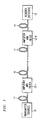
- An optical fiber transmission system as shown in FIG. 1 includes a transmitter, a receiver and a transmission medium interconnecting the transmitter and the receiver.
- Soliton pulses of optical radiation are generated at a nominal soliton center frequency ⁇ by transmitter 10.
- the pulses are then coupled in the transmission medium which comprises lengths of optical fiber 11 and optical amplifiers and filters 12 disposed at predetermined intervals along the transmission medium. After transmission through the transmission medium, the pulses are then detected at receiver 13.
- Unidirectional transmission is depicted in order to simplify the explanation of the principles of the present invention without limiting the scope of the invention. This invention is applicable to bidirectional transmission systems.
- the fundamental principles of the present invention are described in terms of a single channel or single frequency soliton system. It will be briefly described herein that the principles of the present invention are extendible to frequency-division-multiplexed systems utilizing a plurality of different soliton frequency channels.
- soliton pulses are dependent upon proper launch and transmission characteristics such as pulse power, pulse width, center frequency, fiber dispersion and the like. These characteristics are well known to those skilled in the art and will not be discussed further herein.
- soliton generation and soliton transmission see Optical Fiber Telecommunications II , ed. S. E. Miller et al., pp. 90 et seq. (Academic Press 1988) and see also U. S. Patent 4,406,516.
- the transmission medium covers an system path length L between the transmitter and the receiver.
- the system path length is at least several thousand kilometers.
- Such long distance soliton transmission media are generally realized by a plurality of lengths of optical fiber 11 which are desirably single mode optical fibers having the appropriate group velocity dispersion for supporting soliton propagation at frequency ⁇ and, as will be described below, at those frequencies caused by the action of the sliding-frequency guiding filters.
- Silica-based optical fibers are suitable for this application. Fibers employing different materials as well as different properties such as polarization preservation are contemplated for use herein.
- Optical amplifiers and filters 12 are shown as a single element having portions providing optical amplification and optical filtering. In practice, several elements such as separate amplifiers and filters may be desired for realizing element 12.
- Each amplifier portion comprises an optically pumped section of rare earth doped optical fiber to provide gain to pulses propagating at the soliton center frequency.
- Each filtering portion comprises an in-line linear filter having a frequency dependent response characteristic defined around a nominal filter center frequency ⁇ f . The filter response characteristic is selected to provide a suitable amount of bandwidth limiting.
- Optical coupling elements may also be required to transfer the optical pulses to and from each optical amplifier and filter 12. These elements are well known in the relevant art and have not been shown in the FIGs.
- Optical filters are realizable from Fabry-Perot etalons, fiber Fabry-Perot etalons and the like.
- Fiber Fabry-Perot etalon filters have been disclosed in U. S. Patent 4,861,136, U. S. Patent 4,830,451 and U. S. Patent 5,037,180 which are expressly incorporated herein by reference.
- a multiport optical filter utilizing a Fabry-Perot etalon for wavelength selectivity is described in U. S. Patent 5,050,954.
- Other exemplary wavelength-tunable optical filters are described by H. Kobrinski et al. in IEEE Communications Magazine , pp. 53-63 (October 1989), also expressly incorporated herein by reference.
- Etalons exhibit many desirable characteristics such as tunability, appropriate shaping near the response peak, and a periodic comb characteristic which, in the latter instance, lends to their attractiveness for wavelength-division-multiplexing applications.
- Optical amplifiers such as erbium-doped optical fiber amplifiers or Raman amplifiers are used in the system because they amplify the optical signals in the optical domain without requiring an opto-electronic or electrooptic conversion in the process.
- Such amplifiers generally require a pump source for generating the optical pump beam and a means for coupling the pump beam into the optical amplifying medium. These elements are not shown in the FIGs. When operating with the associated filters, it is desirable that each amplifier compensate the loss related to insertion of the associated filter.
- each optical filter in optical amplifier and filter 12-1 through 12-N is set to a nominal filter center frequency ⁇ f,1 through ⁇ f,N , respectively, wherein the nominal filter center frequencies are intentionally detuned from a reference frequency by some prescribed, varying amount.
- the center frequency of the optical filters may be different from each other and from the nominal center frequency ⁇ of the soliton as it is launched into the relevant portion of the transmission system. This allows for the use of stronger filters which, in turn, greatly reduces timing jitter problems in the soliton transmission system.
- the center frequency of each successive optical filter is translated up or translated down in a predetermined pattern such as frequency increasing, frequency decreasing, and combinations of both.
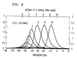
- the use of the sliding-frequency guiding filters in optical amplifiers and filters 12 creates a transmission environment which is substantially opaque to noise while remaining perfectly transparent to solitons. Opacity to noise exists for all but a small fraction of the total system length. This will be described below with respect to FIG. 8.
- An alternative way of describing the transmission environment created by use of the invention is that it permits solitons to leave behind, at some fixed distance and in a different frequency band, the noise emanating from the amplification process. In essence, the solitons are adiabatically and intentionally dragged away in the frequency domain from their related amplified noise.
- the principles of the present invention extend to a system in which at least some relevant portion of the transmission medium includes two or more optical filters exhibiting the sliding-frequency guiding property. For example, it may be desirable to shed dispersive wave radiation via sliding-frequency guiding filters in the initial portion of the system transmission medium while having standard filtering in the remaining portion of the transmission medium. Alternatively, it may be desirable to follow a transmission medium section of positive sliding as in FIG. 3 with a transmission medium section of negative sliding wherein the filter center frequencies decrease over distance.
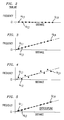
- FIGs. 3-5 Exemplary transmission media exhibiting principles of the sliding-frequency guiding filter invention are shown in FIGs. 3-5.
- the nominal center frequency of each successive filter along the transmission medium increases monotonically with distance. It is contemplated that the nominal center frequencies of consecutive filters can decrease monotonically with distance.
- the nominal center frequencies of consecutive filters are staggered in an alternating pattern around a straight line.
- stagger tuning allows for a cumulative filter transmission shape, attained by consecutive filters such as ⁇ f,1 and ⁇ f.2 , for example, which is flatter near the peak and has steeper sides.
- This altered filter transmission shape in turn allows for stronger guiding of the soliton pulses and greater jitter reduction for a given soliton energy loss. Equivalently, it allows a reduced loss and hence for reduced build-up of noise for a given degree of guiding.
- each filter is shown to comprise two filters at the same nominal center frequency to create overcoupling and, thereby, a stronger filter response as shown by curve 25 in FIG. 7.
- FIGs. 3-5 show substantially equal detuning amounts between the center frequencies of consecutive filters (FIGs. 3 and 5) or alternate filters (FIG. 4), it is contemplated that different or unequal detuning amounts can be employed for the filters along the transmission medium. In other words, the frequency difference between center frequencies of adjacent filters need not be equal for the entire transmission medium. Moreover, the spacing of filters need not occur at regular, periodic intervals nor in conjunction with each and every amplifier. Irregular filters spacings are contemplated within the principles of the present invention.
- the rate of change of nominal center frequency detuning as a function of distance is less than a prescribed maximum. If the maximum rate were exceeded, then amplitude and frequency fluctuations would create an unstable condition leading eventually to the elimination of the soliton pulses.
- the exemplary maximum rate has been determined to be approximately (2/27) ⁇ , where ⁇ describes the curvature per unit soliton length of the parabolically shaped filter response around the peak at the nominal center frequency. Typically, the results of such instabilities are seen over distances on the order of the soliton unit distance, z c .
- the propagation equation for solitons, including filter loss and compensating gain from the amplifying elements, is: where ⁇ and ⁇ are the excess gain and filter peak curvature, respectively, per unit length and where ⁇ f is the nominal peak or center frequency of an optical filter per unit length.
- ⁇ and ⁇ are characterized as continuously distributed quantities, it will be shown immediately below that they are easily converted into lumped, periodic equivalent quantities consistent with the use of lumped periodic amplifying and filtering elements 12.
- the filter effect is regarded as continuously distributed.
- z c is typically at least many hundreds of kilometers long.
- the soliton unit frequency, ⁇ c is one radian per t c .
- FIG. 7 shows the transmission curves for a pair of non-staggered etalons (curve 26) as shown by each filter pair in FIG. 5, a pair of staggered etalons (curve 25) as shown by a pair of adjacent filters in FIG. 4, and a super-Gaussian frequency response spectrum (curve 24) compared with the frequency spectrum of the 20 psec wide soliton (curve 21).
- the soliton unit distance z c is approximately 250 km at a transmission wavelength ⁇ of approximately 1556 nm.
- the filter curvature parameter ⁇ 0.6 a filter strength value about 7.5 times larger than reported in any prior art experiment.
- FIG. 8 shows N( ⁇ ,z) as computed numerically for the particular parameters of the example, essentially according to EQ. (36), except that actual Lorentzian filter functions were used.
- the noise spectral density curve 8 is labelled to denote the noise spectral density curve at a particular distance z in Mm along the transmission medium. Moreover, the curves are normalized to the density achieved at 10Mm for a transmission system without the sliding filters, that is, with conventional identical filters. After about 5Mm, the peak spectral density saturates at a very acceptable level which is slightly greater than 2.0. In the prior art systems without sliding-frequency guiding filters, the peak noise spectral density would have risen at an exponential rate, by nearly e10 ⁇ 20,000 times!
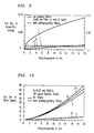
- FIG. 10 the standard deviation in timing jitter is plotted versus the path length. Approximate effects of the acoustic interaction are included as described in Soviet Lightwave Communications , 1 , p. 235 (1991), but as modified by our own experimental measurements described in the Electronics Letters article cited above. The effects are plotted for several different bit rates, 0,10, and 20 Gbps where 0 Gbps represents the pure Gordon-Haus effect described earlier. Solid curves represent system performance without the sliding filters while the dotted curve represents the system performance with sliding filters.
- the standard deviation in timing jitter for the sliding filter system is approximately 2psec, which is suitable for error-free transmission at 20Gbit/s or more per channel, as compared with a standard deviation of 15 psec for the system without sliding filters.
- error-free transmission of higher bit-rate soliton channels is achievable through the use of sliding-frequency guiding filters.
- sliding-frequency guiding filters bring several other important benefits to optical soliton transmission systems.
- the dispersive wave radiation shed by imperfect pulses always remains in the same frequency band with the solitons, and hence can add significantly to the noise.
- sliding-frequency guiding filters such noise tends to be generated entirely in the first fraction of a Megameter of the transmission medium, so that the sliding filters can completely remove the noise long before it reaches the receiver.
- a similar "cleaning" effect applies to another potentially important source of noise, viz., the dispersive wave radiation shed by the solitons as they react to polarization dispersion.
- sliding filters should enable a great reduction in the number of isolators required to suppress the build up of noise from Rayleigh double backscattering. At most, only a handful of isolators would be required to be located desirably near the output end of the system, if at all.
- strong damping constants permitted by sliding filters greatly reduce the various penalties of wavelength-division-multiplexing (WDM), such as from soliton-soliton overlap at the system input.
- WDM wavelength-division-multiplexing
- strong filters substantially help with the problem of equalizing signal strengths among channels.
- Soliton sliding filters have been described above here using only simple, passive, polarization-independent devices which are fully compatible with extensive WDM.
- filtering in the time domain requires active devices, with all the same drawbacks of complexity, reduced reliability, high cost, and incompatibility with WDM that accompany electronic regeneration.
Landscapes
- Physics & Mathematics (AREA)
- Electromagnetism (AREA)
- Engineering & Computer Science (AREA)
- Computer Networks & Wireless Communication (AREA)
- Signal Processing (AREA)
- Optical Communication System (AREA)
Applications Claiming Priority (2)
| Application Number | Priority Date | Filing Date | Title |
|---|---|---|---|
| US904239 | 1992-06-25 | ||
| US07/904,239 US5357364A (en) | 1992-06-25 | 1992-06-25 | Soliton transmission system having sliding-frequency guiding filters |
Publications (2)
| Publication Number | Publication Date |
|---|---|
| EP0576208A1 true EP0576208A1 (fr) | 1993-12-29 |
| EP0576208B1 EP0576208B1 (fr) | 1999-04-14 |
Family
ID=25418831
Family Applications (1)
| Application Number | Title | Priority Date | Filing Date |
|---|---|---|---|
| EP93304721A Expired - Lifetime EP0576208B1 (fr) | 1992-06-25 | 1993-06-17 | Système de transmission utilisant des solitons avec des filtres de guidage à fréquence dérivante |
Country Status (3)
| Country | Link |
|---|---|
| US (1) | US5357364A (fr) |
| EP (1) | EP0576208B1 (fr) |
| JP (1) | JP3290001B2 (fr) |
Cited By (8)
| Publication number | Priority date | Publication date | Assignee | Title |
|---|---|---|---|---|
| EP0700179A1 (fr) * | 1994-08-29 | 1996-03-06 | AT&T Corp. | Système de transmission utilisant des solitons et des filtres de guidage à fréquence dérivante avec des taux particuliers de force et de dérivation |
| FR2724510A1 (fr) * | 1994-09-12 | 1996-03-15 | Kokusai Denshin Denwa Co Ltd | Systeme de transmission optique |
| EP0708539A1 (fr) * | 1994-10-17 | 1996-04-24 | AT&T Corp. | Système de transmission à solitons comportant des groupes de filtres de guidage à fréquence dérivante |
| EP0720312A1 (fr) * | 1994-12-27 | 1996-07-03 | AT&T Corp. | Transmission de données au moyen de solitons avec émetteur non-soliton |
| GB2274952B (en) * | 1993-01-23 | 1996-12-04 | Northern Telecom Ltd | Optical soliton pulse transmission system |
| EP0786877A1 (fr) | 1996-01-23 | 1997-07-30 | Alcatel Submarine Networks | Méthode et dispositif de régénération en ligne d'un signal transmis par solitons multiplexés en longueur d'onde via la modulation synchrone et système de télécommunications optiques utilisant la méthode |
| EP0849899A1 (fr) * | 1996-12-19 | 1998-06-24 | Alcatel | Système de transmission à fibre optique en régime de dispersion normal |
| WO1998035459A1 (fr) * | 1997-02-10 | 1998-08-13 | Alcatel | Procede et dispositif de regeneration en ligne d'un signal transmis par solitons multiplexes en longueur d'onde et systeme de telecommunications optiques comprenant un tel dispositif de regeneration |
Families Citing this family (10)
| Publication number | Priority date | Publication date | Assignee | Title |
|---|---|---|---|---|
| FR2700901B1 (fr) * | 1993-01-28 | 1995-02-24 | Alcatel Nv | Système et procédé de transmission à solitons. |
| FR2707442B1 (fr) * | 1993-07-06 | 1995-09-15 | Pirio Francis | Système de transmission sur fibre optique à compensation des distorsions en ligne. |
| US5546485A (en) * | 1993-12-20 | 1996-08-13 | At&T Corp. | Repeater for soliton transmission system using sliding-frequency guiding filter |
| GB2346025B (en) * | 1995-09-11 | 2000-09-13 | Univ Southampton | Optical pulse propagation |
| US5710649A (en) * | 1995-12-04 | 1998-01-20 | Lucent Technologies Inc. | Apparatus and methods for nulling non-random timing jitter in the transmission of digital optical signals |
| JPH09191303A (ja) * | 1996-01-09 | 1997-07-22 | Kokusai Denshin Denwa Co Ltd <Kdd> | 光伝送路 |
| US5986789A (en) * | 1996-03-07 | 1999-11-16 | Nippon Telegraph And Telephone Corporation | Optical transmission line and optical transmission system |
| US6147788A (en) * | 1997-06-16 | 2000-11-14 | Lucent Technologies Inc | Guiding filters for wavelength division multiplexing in soliton transmission |
| US6414786B1 (en) * | 2000-03-27 | 2002-07-02 | Tycom (Us) Inc. | Method and apparatus for reducing polarization dependent gain in Raman amplification |
| US12463727B2 (en) * | 2022-04-04 | 2025-11-04 | Ciena Corporation | Tunable optical filter in coherent optical transmitters |
Family Cites Families (2)
| Publication number | Priority date | Publication date | Assignee | Title |
|---|---|---|---|---|
| US5117303A (en) * | 1990-08-23 | 1992-05-26 | At&T Bell Laboratories | Method of operating concatenated optical amplifiers |
| US5140656A (en) * | 1991-08-12 | 1992-08-18 | At&T Bell Laboratories | Soliton optical fiber communication system |
-
1992
- 1992-06-25 US US07/904,239 patent/US5357364A/en not_active Expired - Lifetime
-
1993
- 1993-06-17 EP EP93304721A patent/EP0576208B1/fr not_active Expired - Lifetime
- 1993-06-25 JP JP17766693A patent/JP3290001B2/ja not_active Expired - Fee Related
Non-Patent Citations (3)
| Title |
|---|
| JOURNAL OF LIGHTWAVE TECHNOLOGY. vol. 10, no. 4, April 1992, NEW YORK US pages 482 - 487 J.D.MOORES 'Ultra-Long Distance Wavelength-Division-Multiplexed Soliton Transmission Using Inhomogeneously Broadened Fiber Amplifiers' * |
| OPTICS LETTERS. vol. 16, no. 23, 1 December 1991, NEW YORK US pages 1841 - 1843 A.MECOZZI ET AL 'Soliton transmission control' * |
| OPTICS LETTERS. vol. 17, no. 1, 1 January 1992, NEW YORK US pages 34 - 36 D.MARCUSE 'Simulations to demonstrate reduction of the Gordon-Haus effect' * |
Cited By (12)
| Publication number | Priority date | Publication date | Assignee | Title |
|---|---|---|---|---|
| GB2274952B (en) * | 1993-01-23 | 1996-12-04 | Northern Telecom Ltd | Optical soliton pulse transmission system |
| EP0700179A1 (fr) * | 1994-08-29 | 1996-03-06 | AT&T Corp. | Système de transmission utilisant des solitons et des filtres de guidage à fréquence dérivante avec des taux particuliers de force et de dérivation |
| FR2724510A1 (fr) * | 1994-09-12 | 1996-03-15 | Kokusai Denshin Denwa Co Ltd | Systeme de transmission optique |
| EP0708539A1 (fr) * | 1994-10-17 | 1996-04-24 | AT&T Corp. | Système de transmission à solitons comportant des groupes de filtres de guidage à fréquence dérivante |
| EP0720312A1 (fr) * | 1994-12-27 | 1996-07-03 | AT&T Corp. | Transmission de données au moyen de solitons avec émetteur non-soliton |
| EP0786877A1 (fr) | 1996-01-23 | 1997-07-30 | Alcatel Submarine Networks | Méthode et dispositif de régénération en ligne d'un signal transmis par solitons multiplexés en longueur d'onde via la modulation synchrone et système de télécommunications optiques utilisant la méthode |
| EP0849899A1 (fr) * | 1996-12-19 | 1998-06-24 | Alcatel | Système de transmission à fibre optique en régime de dispersion normal |
| FR2757721A1 (fr) * | 1996-12-19 | 1998-06-26 | Alsthom Cge Alcatel | Systeme de transmission a fibre optique en regime de dispersion normal |
| US6317241B1 (en) | 1996-12-19 | 2001-11-13 | Alcatel | Normal dispersion fiber optic transmission system |
| WO1998035459A1 (fr) * | 1997-02-10 | 1998-08-13 | Alcatel | Procede et dispositif de regeneration en ligne d'un signal transmis par solitons multiplexes en longueur d'onde et systeme de telecommunications optiques comprenant un tel dispositif de regeneration |
| FR2759516A1 (fr) * | 1997-02-10 | 1998-08-14 | Alsthom Cge Alcatel | Procede et dispositif de regeneration en ligne d'un signal transmis par solitons multiplexes en longueur d'onde et systeme de telecommunications optiques comprenant un tel dispositif de regeneration |
| US6373608B1 (en) | 1997-02-10 | 2002-04-16 | Alcatel | Method and device for on-line regeneration of a signal transmitted by wavelength division multiplexed solitons and optical telecommunication system comprising such a regenerating device |
Also Published As
| Publication number | Publication date |
|---|---|
| US5357364A (en) | 1994-10-18 |
| JP3290001B2 (ja) | 2002-06-10 |
| JPH06104844A (ja) | 1994-04-15 |
| EP0576208B1 (fr) | 1999-04-14 |
Similar Documents
| Publication | Publication Date | Title |
|---|---|---|
| EP0576208B1 (fr) | Système de transmission utilisant des solitons avec des filtres de guidage à fréquence dérivante | |
| EP0720312B1 (fr) | Transmission de données au moyen de solitons avec émetteur non-soliton | |
| Sayed et al. | An enhanced WDM optical communication system using a cascaded fiber Bragg grating | |
| US5642215A (en) | Optical transmission system | |
| EP0231016A2 (fr) | Système de télécommunication par fibre optique utilisant des solitons | |
| EP0473331A2 (fr) | Système optique de communication à grande distance utilisant des solitons | |
| US5917635A (en) | Optical repeaters for single-and multi-wavelength operation with dispersion equalization | |
| EP0708539B1 (fr) | Système de transmission à solitons comportant des groupes de filtres de guidage à fréquence dérivante | |
| US5966228A (en) | Optical transmission system and optical repeater | |
| US6522450B2 (en) | Loss-less tunable per-channel dispersion compensator | |
| EP0997013B1 (fr) | Systemes de transmission optique utilisant l'inversion spectrale permettant de compenser la dispersion et les non-linearites | |
| US6690886B1 (en) | Suppression of four-wave mixing in ultra dense WDM optical communication systems through optical fibre dispersion map design | |
| US6898351B2 (en) | Optical fiber transmission systems with suppressed light scattering | |
| EP1000474B1 (fr) | Systeme de communication par fibre optique | |
| JPS58157233A (ja) | 光フアイバ遠隔通信装置 | |
| JPH1079703A (ja) | ソリトンフォーマット光学的データ伝送システム | |
| EP0700179A1 (fr) | Système de transmission utilisant des solitons et des filtres de guidage à fréquence dérivante avec des taux particuliers de force et de dérivation | |
| Belmahdi et al. | The performance of an EDFA in a long distance WDM optical network | |
| NZ239641A (en) | Transmitting binary digits using multiple solitons | |
| US7312910B1 (en) | Dispersion-managed soliton transmission system with guiding filters | |
| EP1436920B1 (fr) | Systeme de transmission optique comprenant un systeme de gestion de la dispersion | |
| US20050117862A1 (en) | Transmission of solitons on alternate sign dispersion optical fibres with phase conjugation | |
| Sunak et al. | Design And Computer Simulation Of An All-Optical, Long Distance, Soliton-Based Lightwave Communication System Using Single-Mode Heavy Metal Fluoride Fibers At 2.55 µm | |
| Spalevic et al. | The influence of phase shift of interference on signal propagation along the optical fiber | |
| Tang et al. | Long-distance optical soliton propagation using lumped amplifiers with nonideal gain |
Legal Events
| Date | Code | Title | Description |
|---|---|---|---|
| PUAI | Public reference made under article 153(3) epc to a published international application that has entered the european phase |
Free format text: ORIGINAL CODE: 0009012 |
|
| AK | Designated contracting states |
Kind code of ref document: A1 Designated state(s): FR GB |
|
| RAP3 | Party data changed (applicant data changed or rights of an application transferred) |
Owner name: AT&T CORP. |
|
| 17P | Request for examination filed |
Effective date: 19940615 |
|
| 17Q | First examination report despatched |
Effective date: 19970225 |
|
| GRAG | Despatch of communication of intention to grant |
Free format text: ORIGINAL CODE: EPIDOS AGRA |
|
| GRAG | Despatch of communication of intention to grant |
Free format text: ORIGINAL CODE: EPIDOS AGRA |
|
| GRAH | Despatch of communication of intention to grant a patent |
Free format text: ORIGINAL CODE: EPIDOS IGRA |
|
| GRAH | Despatch of communication of intention to grant a patent |
Free format text: ORIGINAL CODE: EPIDOS IGRA |
|
| GRAA | (expected) grant |
Free format text: ORIGINAL CODE: 0009210 |
|
| RAP1 | Party data changed (applicant data changed or rights of an application transferred) |
Owner name: TYCO SUBMARINE SYSTEMS LTD. |
|
| AK | Designated contracting states |
Kind code of ref document: B1 Designated state(s): FR GB |
|
| ET | Fr: translation filed | ||
| PLBE | No opposition filed within time limit |
Free format text: ORIGINAL CODE: 0009261 |
|
| STAA | Information on the status of an ep patent application or granted ep patent |
Free format text: STATUS: NO OPPOSITION FILED WITHIN TIME LIMIT |
|
| 26N | No opposition filed | ||
| REG | Reference to a national code |
Ref country code: GB Ref legal event code: IF02 |
|
| PGFP | Annual fee paid to national office [announced via postgrant information from national office to epo] |
Ref country code: FR Payment date: 20080617 Year of fee payment: 16 |
|
| PGFP | Annual fee paid to national office [announced via postgrant information from national office to epo] |
Ref country code: GB Payment date: 20080627 Year of fee payment: 16 |
|
| GBPC | Gb: european patent ceased through non-payment of renewal fee |
Effective date: 20090617 |
|
| REG | Reference to a national code |
Ref country code: FR Ref legal event code: ST Effective date: 20100226 |
|
| PG25 | Lapsed in a contracting state [announced via postgrant information from national office to epo] |
Ref country code: FR Free format text: LAPSE BECAUSE OF NON-PAYMENT OF DUE FEES Effective date: 20090630 |
|
| PG25 | Lapsed in a contracting state [announced via postgrant information from national office to epo] |
Ref country code: GB Free format text: LAPSE BECAUSE OF NON-PAYMENT OF DUE FEES Effective date: 20090617 |