EP0576271A2 - Dispositif de protection pour un onduleur - Google Patents
Dispositif de protection pour un onduleur Download PDFInfo
- Publication number
- EP0576271A2 EP0576271A2 EP93304911A EP93304911A EP0576271A2 EP 0576271 A2 EP0576271 A2 EP 0576271A2 EP 93304911 A EP93304911 A EP 93304911A EP 93304911 A EP93304911 A EP 93304911A EP 0576271 A2 EP0576271 A2 EP 0576271A2
- Authority
- EP
- European Patent Office
- Prior art keywords
- frequency
- inverter
- phase
- power
- voltage
- Prior art date
- Legal status (The legal status is an assumption and is not a legal conclusion. Google has not performed a legal analysis and makes no representation as to the accuracy of the status listed.)
- Granted
Links
Images


Classifications
-
- H—ELECTRICITY
- H02—GENERATION; CONVERSION OR DISTRIBUTION OF ELECTRIC POWER
- H02H—EMERGENCY PROTECTIVE CIRCUIT ARRANGEMENTS
- H02H7/00—Emergency protective circuit arrangements specially adapted for specific types of electric machines or apparatus or for sectionalised protection of cable or line systems, and effecting automatic switching in the event of an undesired change from normal working conditions
- H02H7/10—Emergency protective circuit arrangements specially adapted for specific types of electric machines or apparatus or for sectionalised protection of cable or line systems, and effecting automatic switching in the event of an undesired change from normal working conditions for converters; for rectifiers
- H02H7/12—Emergency protective circuit arrangements specially adapted for specific types of electric machines or apparatus or for sectionalised protection of cable or line systems, and effecting automatic switching in the event of an undesired change from normal working conditions for converters; for rectifiers for static converters or rectifiers
- H02H7/122—Emergency protective circuit arrangements specially adapted for specific types of electric machines or apparatus or for sectionalised protection of cable or line systems, and effecting automatic switching in the event of an undesired change from normal working conditions for converters; for rectifiers for static converters or rectifiers for inverters, i.e. DC/AC converters
- H02H7/1227—Emergency protective circuit arrangements specially adapted for specific types of electric machines or apparatus or for sectionalised protection of cable or line systems, and effecting automatic switching in the event of an undesired change from normal working conditions for converters; for rectifiers for static converters or rectifiers for inverters, i.e. DC/AC converters responsive to abnormalities in the output circuit, e.g. short circuit
-
- H—ELECTRICITY
- H02—GENERATION; CONVERSION OR DISTRIBUTION OF ELECTRIC POWER
- H02J—ELECTRIC POWER NETWORKS; CIRCUIT ARRANGEMENTS OR SYSTEMS FOR SUPPLYING OR DISTRIBUTING ELECTRIC POWER; SYSTEMS FOR STORING ELECTRIC ENERGY
- H02J3/00—Circuit arrangements for AC mains or AC distribution networks
- H02J3/38—Arrangements for feeding a single network from two or more generators or sources in parallel; Arrangements for feeding already energised networks from additional generators or sources in parallel
- H02J3/381—Dispersed generators
-
- H—ELECTRICITY
- H02—GENERATION; CONVERSION OR DISTRIBUTION OF ELECTRIC POWER
- H02M—APPARATUS FOR CONVERSION BETWEEN AC AND AC, BETWEEN AC AND DC, OR BETWEEN DC AND DC, AND FOR USE WITH MAINS OR SIMILAR POWER SUPPLY SYSTEMS; CONVERSION OF DC OR AC INPUT POWER INTO SURGE OUTPUT POWER; CONTROL OR REGULATION THEREOF
- H02M7/00—Conversion of AC power input into DC power output; Conversion of DC power input into AC power output
- H02M7/42—Conversion of DC power input into AC power output without possibility of reversal
- H02M7/44—Conversion of DC power input into AC power output without possibility of reversal by static converters
- H02M7/48—Conversion of DC power input into AC power output without possibility of reversal by static converters using discharge tubes with control electrode or semiconductor devices with control electrode
-
- H—ELECTRICITY
- H02—GENERATION; CONVERSION OR DISTRIBUTION OF ELECTRIC POWER
- H02J—ELECTRIC POWER NETWORKS; CIRCUIT ARRANGEMENTS OR SYSTEMS FOR SUPPLYING OR DISTRIBUTING ELECTRIC POWER; SYSTEMS FOR STORING ELECTRIC ENERGY
- H02J2101/00—Supply or distribution of decentralised, dispersed or local electric power generation
- H02J2101/10—Dispersed power generation using fossil fuels, e.g. diesel generators
-
- H—ELECTRICITY
- H02—GENERATION; CONVERSION OR DISTRIBUTION OF ELECTRIC POWER
- H02J—ELECTRIC POWER NETWORKS; CIRCUIT ARRANGEMENTS OR SYSTEMS FOR SUPPLYING OR DISTRIBUTING ELECTRIC POWER; SYSTEMS FOR STORING ELECTRIC ENERGY
- H02J3/00—Circuit arrangements for AC mains or AC distribution networks
- H02J3/38—Arrangements for feeding a single network from two or more generators or sources in parallel; Arrangements for feeding already energised networks from additional generators or sources in parallel
- H02J3/388—Arrangements for the handling of islanding, e.g. for disconnection or for avoiding the disconnection of power
Definitions
- the present invention relates to a protection device for an inverter in which DC power is converted to AC power and supplied to a load and operation is effected with connection to an AC power system.
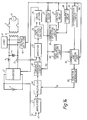
- FIG. 24 Atypical example of a conventional inverter protection device is shown in Fig. 24 and will now be described.
- the DC power of a DC power source 1 constituted by a solar battery or a fuel battery, etc. is converted to AC power by an inverter 2 of the PWM (pulse width modulation) controlled type.
- the AC power is removed its high-frequency components resulted from PWM control by a filter constituted by a reactor 3 and a capacitor 4 and is supplied to a load 9.
- the load 9 is also supplied with h AC power for general domestic use that is supplied from an AC power system 8 via a circuit breaker 7 and a pole-mounted transformer 6, and operation is effected with the AC power of t he inverter interconnected to the AC power system 8.
- the AC voltage supplied to the load 9 is detected by a voltage detector 10, and a sine wave signal Vs is input into a current reference circuit 12 via a bandpass filter 16.
- the current reference circuit 12 multiplies the sine wave signal Vs and a control signal Vc output by an amplifier 11 and outputs a current reference I*.
- the current reference I* and an output current I of the inverter 2 that is detected by a current detector are input into an amplifier 13 and PWM control of the inverter 2 such as to make the current deviation zero is effected via a PWM control section 14 and a drive section 15.
- the phase of the current reference I* is approximately coincident with the phase of the AC voltage supplied to the load 9 and high powerfactorAC power is supplied from the inverter 2.
- a voltage reference V* is set so as to take out maximum power.
- the amplifier 11 generates the control signal Vc to the current reference circuit 12 so that an output voltage V of the DC power source 1 is coincident with the voltage reference V*.
- a frequency fluctuation system, a bandpass filter system, a power fluctuation system and a higher harmonic voltage monitoring system as noted below have been proposed for the prevention of the islanding, and these systems will now be described.
- a phase shift of a fixed low frequency is applied by means of a fluctuation circuit 21 to the phase of the system reference voltage input to the current reference circuit 12. Islanding is detected from the fluctuation of the inverter output frequency that takes place when the circuit breaker 7 is opened.
- the inverter power (including reactive power) and the load power are perfectly balanced, the frequency and voltage will be unchanged, with the result that detection of islanding will not be success- fu
- the magnitude and phase of the current reference 1* of Fig. 24 are as shown in Fig. 25.
- the frequency of the AC voltage supplied to the load 9 shifts from the rated frequency f o , the value of the current falls, the effective power balance is lost, the AC voltage falls, the voltage relay 17 detects an abnormality and the inverter 2 is stopped.
- the load impedance consists of a resistor R and a reactor L shown in Fig. 26(a) and has a lagging power factor angle shown in Fig. 26(b)
- the inverter 2 In a situation in which the inverter 2 is connected to an AC power system with a large power capacity, it operates at the rated frequency f o and so, because of the bandpass filter characteristic of Fig. 25, the inverter 2 outputs power with a power factor of 1.
- the frequency of the output voltage of the inverter 2 rises because of the lagging power factor angle of the load 9.
- the inverter 2 supplies power whose phase lags by the lagging power factor angle ⁇ , because of the characteristic of the bandpass filter 16. That is, the inverter 2 functions to lower its output frequency.
- the value of the current only falls slightly from l o to 1 1 and the fluctuation of the voltage is not large. This voltage fluctuation is determined by the supplied active power and the active power consumed by the load 9.
- the bandpass filter 16 acts to suppress system frequency fluctuation at the time of islanding.
- the inverter 2 functions to rise its output frequency and the bandpass filter 16 acts to suppress lowering the frequency. Since at the time of islanding, the action of the bandpass filter 16 is directed towards an increase of voltage fluctuation but is directed towards suppression of frequency fluctuation, depending on conditions, detection of islanding may be delayed.
- the fluctuation circuit 21 in Fig. 24 causes the current reference I* output from the current reference circuit 12 to fluctuate at a low frequency within a set range. And when the circuit breaker 7 is opened, the balance between the power (reactive power and active power) output by the inverter 2 and the load power breaks down and consequently voltage and frequency fluctuation is caused and islanding is detected.
- the phases of the power fluctuation of the various inverters 2 are different from one another and consequently the state is one in which overall there is no power fluctuation and detection is not possible.
- Voltage harmonics on the load side are monitored by a higher harmonic detection circuit 20, and when the circuit breaker 7 is opened, islanding is detected through the fact that there is an increase in higher harmonics (3rd, 5th and 7th harmonics).
- a higher harmonic detection circuit 20 When this system, however, if a large number of loads 9 are used which have capacitor input type rectification circuits as in inverter air conditioning or television equipment, etc., there is a considerable fall in the reliability of detection, since there is an increase in 3rd, 5th and 7th harmonics at normal times.
- one object of this invention is to provide an inverter protection device which can detect islanding with good reliability.
- a protection device for an inverter which is connected to an AC power system, converts DC power into AC power, supplies the AC power to a load and includes a control circuit for detecting a phase and a frequency of an output voltage, for generating a current reference synchronized with the output voltage and for controlling the inverter such that an output current is coincident with the current reference.
- the protection device includes a first detection circuit for detecting that an AC output is disconnected from the AC power system based on an electrical quantity of the output voltage and for generating a detection signal based on a detection result, and a correction circuit connected to receive the detection signal for generating a correction signal to break a power balance between an output power and a power consumed by the load.
- the control circuit corrects the current reference by the correction signal and controls the inverter based on the current reference thus corrected thereby to break the power balance.
- the protection device also includes a second detection circuit for detecting that the power balance is broken and for generating an abnormality signal to stop operation of the inverter based on a detection result.
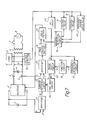
- Fig. 1 is a block diagram showing an inverter protection device according to an embodiment of the invention.
- AC voltage detected by the voltage detection circuit 10 is input via the bandpass filter 16 into a frequency detection circuit 22, the frequency is detected here and the detected frequency V 22 is input into a frequency change ratio (df/dt) detection circuit 23 and an arithmetic circuit 24.
- a frequency change ratio (df/dt) V 23 detected in the frequency change ratio detection circuit 23 is input into the arithmetic circuit 24.
- the frequency V 22 and the frequency change ratio V 23 are added in a set ratio in the arithmetic circuit 24 and an output V 24 (f+a (df/dt) : a is a coefficient) is input into a coefficient setting circuit 30.
- the AC voltage detected by the voltage detection circuit 10 is also supplied via a voltage instantaneous value detection circuit 25 to a voltage effective value calculation circuit 26.
- An effective value V 26 is determined in the voltage effective value calculation circuit 26 and is input into the voltage relay 17.
- the effective value V 26 is compared here with a set voltage value, and an AC voltage abnormality is detected and is input into the abnormality detection circuit 19.
- the frequency V 22 of the AC voltage detected by the frequency detection circuit 22 is also input into the frequency relay 18.
- the frequency V 22 is compared with a set frequency and a frequency abnormality is detected here, and is input into the abnormality detection circuit 19.
- the AC voltage detected by the voltage detector 10 is input into a zero crossover detector 28, voltage zero crossover is detected here and the detected value is input into a distortion detector 27.
- the voltage instantaneous value detected by the voltage instantaneous value detection circuit 25 is also supplied to the distortion detector 27.
- the distortion detector 27 detects a distortion value V 27 in the vicinity of the AC voltage zero crossover and inputs the detection value V 27 to a distortion relay 32.
- the case where the detection value V 27 is greater than a set value is detected by the distortion relay 32 and input into the abnormality detection circuit 19.
- a stop command is supplied to the drive section 15 from the abnormality detection circuit 19 when at least one of the output signals of the voltage relay 17, frequency relay 18 and distortion relay 32 is input into the abnormality detection circuit 19.
- the detection value V 27 of the distortion detector 27 is input into a distortion change detector 33 which detects a distortion change, and an inverted value (- ⁇ ) of the detection value is supplied to the coefficient setting circuit 30.
- the current reference I* from the current reference circuit 12 and the effective value V 26 calculated by the voltage effective value calculation circuit 26 are input into a change ratio detection circuit 29, which detects a change ratio dV/dl* and inputs it into the coefficient setting circuit 30.
- the coefficient setting circuit 30 outputs coefficients F1 and F2 by weighting the input values V 24 , - ⁇ and dV/dl*. The detail of the coefficient setting circuit 30 will be described later.
- the outputs F1 and F2 of the coefficient setting circuit 30 are input into a phase/gain setting circuit 31 which has a structure such that the phase and gain of the current reference I* can be changed.
- phase/gain setting circuit 31 The detail of the phase/gain setting circuit 31 will be described later.
- a sine wave signal V 31 determined by the phase and gain set in the phase/gain setting circuit 31 is input to the current reference circuit 12.
- the current reference circuit 12 multiplies the sine wave signal V 31 and the control signal Vc output from the amplifier 11 and outputs the current reference I* based on the multiplication result.
- Fig. 2 shows an example of the characteristics of the phase and gain set by the phase/gain setting circuit 31 based on the coefficients F1 and F2 output from the coefficient setting circuit 30.
- the frequency is f o and the filter capacitor 4 is regarded as the load.
- the frequency V 22 and the frequency change V 23 are detected and the arithmetic circuit 24 determines the value V 24 , i.e., f+a (df/dt) (a is a coefficient) based on the input values V 22 and V 23 .
- the coefficient values F1 and F2 are set by the coefficient setting circuit 30 taking the value V 24 as a weighting.
- the phase/gain setting circuit 31 determines the phase and gain of the sine wave signal V 31 based on the input coefficient values F2 and F1, as shown in Fig. 2. Then the phase and magnitude of the current reference I* are changed based on the sine wave signal V 31 , thereby to change the phase and magnitude of the inverter current.
- the frequency of the AC voltage rises still further, since the load current and inverter current phases are not matched. As this operation constitutes positive feedback, the frequency rises still further toward infinity. But if the characteristic is so set that, as shown in Fig. 2, the current phase lags when the coefficient value F2 goes beyond a certain range, the load and inverter power factors are matched and a balance is established at, e.g., a point Fa, where the line L o showing the phase characteristic crosses the line L 1 showing the lagging phase angle of the load 9.
- the effect is that in order to make the inverter power factor and the load powerfactor match, there is an action to balance reactive power through a fall in the voltage frequency, a fall in the capacitor current and an increase in reactor current. Since the frequency falls and f+a (df/dt) ⁇ f o , the coefficient setting circuit 30 outputs the coefficient value F2 smaller than the rated value f o . The phase determined by the coefficient F2 is lagging as shown in Fig. 2(b). Accordingly, there is control such that the inverter current lags and so, the frequency of the AC voltage falls still further.
- the AC voltage frequency falls still further toward zero. But if the characteristic is so set that, as shown in Fig. 2, the current leads when the coefficient value F2 goes below a certain value, the load and inverter power factors are matched and a balance is established at, e.g., a point Fb, where the line L o showing the phase characteristic crosses the line L 2 showing the leading phase angle of the load 9.
- the frequency relay 18 is, e.g., set at points Fx or Fy, islanding can easily be detected and the inverter can be stopped when the difference A Q is not 0.
- Fig. 26(c) active power is consumed only by a resistor R, since a capacitor C and a reactor L do-not consume active power. If the voltage applied to the load 9 is designated as (V+ A V) (V is the rated voltage), the power consumed by the resistor R is (V+ ⁇ V) 2 /R. A V is the amount of voltage change in islanding.
- a P [(V+ A V) 2 /R]-[V 2 /R], and so if the difference ⁇ P is more than a set amount, the voltage (V+ A V) is more than a set value and becomes larger than the set voltage, and it is detected by the voltage relay 17 and the inverter 2 can be stopped.
- Fig. 3(a) shows the relation between AC voltage V AC and the excitation current i ex of the pole-mounted transformer 6. Because of the core's saturation characteristic, the excitation current i ex differs from a sine wave and has a peak current form in the vicinity of AC voltage zero crossover. When the circuit breaker 7 is closed, the excitation current i ex is supplied from the AC power system 8 and sinusoidal voltage V AC with little voltage distortion is maintained.
- This distortion is detected by the distortion detection circuit 27 and the distortion change detection circuit 33 so as to detect the possibility of islanding.
- the distortion change detector 33 applies the inverted value (- ⁇ ) of the detected value of the distortion change to the coefficient setting circuit 30, which sets the coefficient values F1 and F2 based on the inverted value (- ⁇ ).
- the phase-gain setting circuit 31 outputs the signal V 31 with the phase and gain determined by the coefficient values F1 and F2 based on the characteristics shownin Fig. 2.
- the horizontal axis F1 of the gain characteristic and the horizontal axis F2 of the phase characteristic in Fig. 2 are shifted toward negative direction and the power balance is broken, the frequency and voltage are caused to fluctuate and the inverter 2 is stopped by operating the voltage relay 17 and frequency relay 18.
- the inverter 2 it is also possible for the inverter 2 to be stopped via the abnormality detection circuit 19 directly by the distortion relay 32 when the output V 27 of the distortion detection circuit 27 becomes more than a set value, not via the coefficient setting circuit 30 and the phase/gain setting circuit 31.
- the distortion change detection circuit 33 When an increase in distortion is detected by the distortion change detection circuit 33 and the horizontal axis F1 is shifted, the current reference I* changes.
- the change ratio dV/dl* is detected by the voltage change ratio (dV/dl*) circuit 29. And it is also possible to add a circuit for breaking the balance by effecting positive feedback to the horizontal axis F1 when the change ratio dV/dl* exceeds a set value in an islanding state.
- the coefficient setting circuit 30 outputs the coef- ficientvalues F1 and F2 by weighting the input values V 24 , - ⁇ and dV/dl*.
- the input values are weighted according to the following order of priority.
- a next step is tried. Specifically, it is set that and and the same dt dt confirmation as described above is made. If the abnormality is not detected within the set time, a further next step is tried, in which the coefficient values F1 and F2 are set by adding the inverted value (- ⁇ ) with weights to the previously set coefficient values F1 and F2, respectively. Then the same confirmation is made.
- the coefficient values F1 and F2 are set in the condition that several weights are selected and the confirmation is made whether or not the abnormality can be detected within the set times in such condition with a well-known simulation method.
- the function of the coefficient setting circuit 30 is as described above, and can be easily implemented by a microcomputer or a combination of well-known hardware components by those skilled in the art. So, the detailed description of the construction of the coefficient setting circuit 30 may be omitted.
- the phase/gain setting circuit 31 sets the gain and phase for the current reference I* based on the coefficient values F1 and F2 set by the coefficient setting circuit 30 and outputs the sine wave signal V 31 based on the set result.
- the phase is set so as to shift in the direction to diverse the frequency based on the input coefficient value F2.
- the phase is set so as to advance or delay in accordance with the rise orfall of the frequency.
- the phase is set such that the phase is advanced or delayed according to the increase or decrease of the frequency change ratio df/dt.
- the coefficient value F2 includes the inverted value (-p ) of the distortion change ratio is described below.
- the phase is set so as to delay thereby to decrease the frequency based on the coefficient value F2.
- the phase is set so as to advance thereby to increase the frequency.
- the gain it is set based on the coefficient value F1. Examples of setting the gain are shown in Fig. 2(a) and Fig. 4(b).
- the gain is set so as to lower it thereby to lower the inverter current when the frequency deviation becomes large.
- the control circuit of Fig. 1 can easily be produced by using a microprocessor and a memory circuit.
- characteristics set by the phase/gain setting circuit 31 which are similar to those of the bandpass filter 16 in respect of gain but in which the phase characteristic is completely inverse can be freely stored in a memory circuit. In an analog circuit, this can be achieved by making separate use of a bandpass filter characteristic and a notch filter phase characteristic.
- control may be effected with addition of the phase characteristics of Fig. 2 to power factor control angles.
- the phase/gain setting circuit 31 of Fig. 1 can of course be realized by using the fitter having the characteristics shown in Fig. 5 and Fig. 6.
- the coefficient setting circuit 30 outputs the frequency f as the coefficient values F1 and F2 to the phase/gain setting circuit 31.
- the characteristics of Fig. 5 and Fig. 6 can easily be produced by using analog filter technology (especially switched capacitorf iIters).
- analog filter technology especially switched capacitorf iIters.
- the phase/gain setting circuit 31 sets the gain by the gain characteristics of an output V 16a and the phase by the phase characteristics of an output V i6b and generates the single V 31 based on the gain and phase thus set.
- characteristics such as shown in Fig. 6(b) can be obtained by connecting bandpass filters 16c and 16d with gain characteristics 16c and 16d and with slightly different center frequencies (f 1 and f 2 ) shown in Fig. 6(b), respectively, in series as shown in Fig. 6(a).
- the bandpass filter 16a has f o as its center frequency.
- the phase/gain setting circuit 31 sets the gain and the phase by the gain and the phase characteristics of the output of V16a and an output of V16d, respectively, and generates the signal V31 based on the gain and phase thus set.
- phase and gain characteristics by adding the outputs of the bandpass filters 16c and 16d and use the characteristics for setting the phase and the gain in the phase/gain setting circuit 31.
- the embodiment of the present invention described above makes it possible to provide an inverter protection device with which islanding is prevented with good reliability.
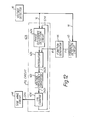
- the AC voltage V 1 supplied to load 9 is detected through the voltage detector 10 and a signal SY synchronized with the AC voltage V 1 is obtained by a PLL (phase locked loop) circuit 42.
- PLL phase locked loop
- a frequency detection circuit 45 detects the frequency f of the AC voltage V 1 from the signal SYand a function generator 44 generates a signal 0 corresponding to the frequency f. The detail of the function generator 44 will be described later.
- a phase shift circuit 43 outputs a synchronization signal SYX whose phase changes depending on the signal 0 . In this case, if the AC voltage V 1 is of the rated frequency, the synchronization signal SYX of phase such that the power factor is practically 1 is output.
- Asine wave synchronized with the AC voltage V 1 is obtained by a sine wave circuit 46 through the phase shift circuit 43 from this single SY and is applied to the current reference circuit 12.
- a sine wave current reference I* having an amplitude proportional to the output Vc of the amplifier 11 and synchronized with the AC voltage V 1 is output from the current reference circuit 12.
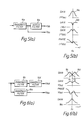
- FIG. 8 An example of a function generator 44 is shown in Fig. 8.
- (a) shows the case where the phase is advanced or is lagged in proportion to the rise or fall in frequency with respect to the rated frequency f o , respectively, and is limited to a fixed limit.
- (c) shows the method in which the change of phase is gentle in the vicinity of the rated frequency f o , but as the frequency departs more from the rated frequency f o , the phase shift is increased.
- the output of voltage detector 10 (in general, a transformer is employed) is applied to the voltage relay 17, frequency relay 18 and a frequency change ratio relay 47 which detects the amount of change of the frequency.
- the outputs of the three relays 17, 18 and 47 are applied to the abnormality detection circuit 19, which detects abnormality and shuts down the inverter 2 by turning off the drive section 15.
- the output current of the inverter has a powerfactor of approximately 1 i.e. it is controlled such that the voltage V and the inverter current I INV are practically in the same phase.
- the frequency is raised in order for the inverter output current and load current to be operated in balance.
- An operation is effected in the direction such as to raise the frequency of the AC voltage so as to reduce the current flowing in inductance L.
- the frequency detection circuit 45 detects the rise in frequency and acts to slightly advance the current phase of the inverter. When this happens, there is a positive action to further raise the frequency of the AC power source to produce a state of balance between the load current and the inverter current.
- the frequency relay 18 and the frequency change ratio relay 47 detect the rapid increase in frequency of the AC power source.
- the inverter2 is then shut down by abnormality detection circuit 19. Specifically, in the case of a lagging power factor load, the device acts positively to destroy balance by supplying an advance current.
- phase shift circuit 43 When frequency detection circuit 45 detects the drop in frequency, the phase shift circuit 43 is actuated to delay the inverter current phase. Thereupon, there is a further fall in frequency and the phase of the voltage of the capacitor C is delayed. That is, positive action takes place to lower the frequency, thereby producing a rapid drop in the frequency of the AC power source. In other words, balance is rapidly lost by supplying a lagging current to an advanced power factor load.
- the frequency of the back electromotive force of the induction motor 1M is proportional to the frequency (f-fs) (where fs is the "slip" frequency) i.e. it is proportional to the speed of revolution of the induction motor IM. (f is the power source frequency). Consequently, when the current is broken by the circuit breaker 7, the frequency of the AC power source is (f - fs).
- the frequency change is increased by shifting the current phase of the inverter 2 in the direction such as to promote frequency change on islanding.
- This change is detected by the frequency relay or the frequency change ratio relay 47 and the inverter 2 is thereby shut down.
- An inverter protection device can thereby be obtained in which islanding can be rapidly prevented.
- FIG. 10 Another embodiment of this invention is illustrated in Fig. 10.
- a filter circuit 16 is inserted ahead of the PLL circuit 42 in Fig. 7, and a filter phase correction circuit 48 is provided that corrects the amount of phase shift produced by the filter circuit 16 in the necessary frequency range.
- an adder circuit 46 is provided that adds the output of the filter phase correction circuit 48 and the output of the function generator 44.
- exactly the same action as in Fig. 7 can be performed by detecting the frequency by means of the frequency detection circuit 45, and applying a phase shift by means of the phase shift circuit 43 based on the output of the adder circuit 29.
- the accuracy of detection of islanding can be increased by adding a distortion rate detection circuit as an input to the abnormality detection relay 19.
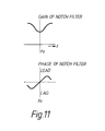
- the circuit for advancing or delaying the phase when frequency rises or falls can be constituted as a notch filter having the characteristic as shown in Fig. 11. This can be used as the function generator 44.
- the frequency relay 18 may be employed that identifies islanding atsayi 1 Hz of the rated frequency. It is therefore sufficient to advance or delay the phase within this range.
- the phase of the AC voltage V1 is detected by the PLL circuit 42.
- the output signal SY is applied to the phase shift circuit 43 and the frequency detection circuit45.
- This invention is not limited to this embodiment. It is possible that the phase shift action is effected in the PLL circuit 42A as shown in Fig. 12.
- a phase difference detection circuit 42a detects the phase difference between the AC voltage V1 and the output signal SYX of a 1/N counter 42d.
- An integrator 42b integrates the phase difference in positive or negative polarity depending on the advanced or lagging phase difference and generates a signal S42b.
- a voltage-frequency converter 42c generates a frequency S42c proportional to the signal S42b.
- the 1/N counter 42d counts down the frequency S42c to generate the signal SYX.
- the PLL circuit constitutes a phase locked loop in which the phase of the signal V 1 is the same as that of the signal SYX.
- the frequency detection circuit 45 is directly connected to the voltage detector 10 and detects the frequency f of the AC voltage V 1 .
- the function generator 44 generates the signal 0 corresponding to the frequency f as in the embodiment of Fig. 7.
- the signal 0 is input to the integrator 42b in the PLL circuit 42A.
- the integrator 42b adds the signal 0 and the phase difference applied by the phase difference detection circuit 42a and performs the above-described integration based on the added result.
- the output signal SYX of the PLL circuit 42A is then applied to the sine wave circuit 46 to change the phase of the output signal.
- Fig. 12 can be changed into that shown in Fig. 13.
- an integrator 42e is provided between the function generator44 and PLL circuit 42B.
- An output signal S42e of the integrator 42e is input to the voltage-frequency converter 42c, which generates the frequency S42c proportional to the added value of the signal S42b and the signal S42e. It is easily understood that the same action as in Fig. 12 can be performed in the embodiment shown in Fig. 13.
- the PLL circuit 42, the phase shift circuit 43, the frequency detection circuit 45, the sine wave circuit 46 and the frequency change rate relay 47, and so on are well known to those skilled in the art. So, the detailed description of their circuit constructions may be omitted.
- This embodiment shows the details of the distortion detector 27 and the distortion change detector 33 and also another embodiment of an inverter protection device according to this invention.
- FIG. 14 Another embodiment of an inverter protection device according to this invention is shown in Fig. 14.
- a differentiation circuit 52 detects the rate of change of voltage of the AC voltage of the load side that is detected by the voltage detector 10.
- a zero cross detection unit 53 detects the zero cross time point of the AC voltage of the load side from the output of the filter 16.
- a comparison and decision unit 54 detects the islanding condition from the AC voltage and the rate of change of the AC voltage on the load side at prescribed times before and after the zero cross time point.
- a function generator 55 outputs a time function signal Vf for changing the output power of the inverter in response to an instruction from the comparison and decision unit 54.
- a multiplier 56 outputs the result of multiplying the output signal Vc of the amplifier 11 and the output signal Vf of the function generator 55.
- the current reference circuit 12 outputs the current reference I* obtained by multiplying the output of the multiplier 56 by the sine wave signal Vs that is output from the filter 16.
- a pole transformer In the core characteristic of the transformer 6 (typically, a pole transformer), as shown in Fig. 15(a), magnetic flux is in non-linear relationship with the exciting current.
- a pole transformer is used with a fairly high magnetic flux density. So, as shown in Fig. 15(b), an exciting current with a high peak value different from a sine wave is employed in order to generate a sine wave magnetic flux.
- a sine wave current of power factor 1 is supplied, so, in the vicinity of zero cross, a sufficient exciting current as shown in Fig. 15(c) cannot be achieved. This therefore results in distortion of the voltage waveform. Specifically, in the vicinity of zero cross, the voltage is lower than a sine wave voltage.
- the comparison and decision circuit 54 identifies the islanding condition from the distortion of the voltage waveform in this zero cross vicinity.
- Fig. 17 shows the voltage rate of voltage change in the vicinity of zero cross.
- the broken line shows the case of a sine wave waveform when the circuit breaker 7 is closed, and the continuous line shows the case of the islanding condition when the circuit breaker 7 is open.
- the exciting current supplied from the inverter 2 is insufficient in the zero cross vicinity, so that the voltage in terms of its absolute value becomes lower than the sine wave voltage Vp C1 , as shown by voltage V A ⁇ 2 .
- the differentiated value of the voltage i.e. the rate of voltage change has a value which differs greatly from that of a sine wave, and islanding can thereby be easily detected.
- Fig. 18 shows a specific embodiment of the comparison and decision unit 54.
- harmonic voltages such as third, fifth and seventh harmonics are detected by means of third, fifth and seventh band pass filters 71, 72 and 73 from the AC voltage V AC or its differentiated value dV Ac/ dt, and the islanding condition is identified in a decision unit 75 from these harmonic voltages by actuating a relay 74 in the vicinity of the zero cross detected by the zero cross detection unit 53.
- the comparison and decision circuit 54 when it detects the islanding condition, outputs a start-up instruction to the function generator 55.
- function generator 55 When function generator 55 receives this instruction, it changes signal Vf, which normally has a fixed value, to a time-wise-varying signal (e.g. a signal that decreases with passage of time, or a signal that oscillates slowly), which is output.
- This signal Vf is input to the multiplier 56, causing the current reference 1* of the current reference circuit 12 to change, and thereby changing the output current of the inverter 2.
- the balance condition between the load power and inverter output power is destroyed, changing the voltage or frequency. This change is detected by the voltage relay 17 or the frequency relay 18, triggering the abnormality detection circuit 19 and stopping the operation of the inverter 2.
- the function generator 55 can easily be constructed specifically by those skilled in the art based on the above description. Accordingly, the detailed description of the construction of the function generator 55 may be omitted.
- Fig. 14(b) shows a circuit construction of a typical example of a capacitor input type rectification load.
- an AC power is supplied from an AC power source 61 to a diode bridge circuit 63 through a capacitor for power factor improvement use.
- the diode bridge circuit 63 rectifies the AC power.
- the rectified power is smoothed by a capacitor 64 and is supplied to a load 65.
- a current l Ac having a peak value in the vicinity of the maximum value of the AC voltage flows.
- the inverter since the inverter will not be immediately shut down even if the comparison and decision unit 54 erroneously detects islanding for a short time, the sensitivity of detection of islanding can be set to a high level.
- identification of islanding by the comparison and decision unit 54 could be achieved by finding the integrated value of the absolute value of the voltage difference between the voltage V AC2 and the sine wave voltage V AC1 in a prescribed range of electrical angle (e.g. a range of ⁇ 30° ) before and after the zero cross point, the islanding condition being identified as when this integrated value exceeds a prescribed value. It is also possible to identify the islanding condition as being when the rate of voltage change (dV Ac2 /dt) in the vicinity of zero cross is non-monotonic.
- Fig. 14 is an embodiment in which the output power of the inverter 2 is made to fluctuate by means of the output signal of the function generator 55 when an islanding condition is detected.
- phase fluctuation or frequency fluctuation of the sine wave signal that is input to the current reference circuit 12 and to shut down the inverter 2 in response to this when an islanding condition is detected.
- a current control system that outputs a sine wave current at high power factor, and as shown in Fig. 19, control is effected such as to output AC voltage V AC and same- phase AC current l Ac .
- Current control can be performed so as to positively make zero the current in the vicinity of the zero cross of this AC current, as shown at l Ac , of Fig. 19.
- the voltage waveform in the vicinity of the zero cross is positively distorted so that the islanding condition can be reliably detected. If the detection of the islanding condition is reliable, a construction can be adopted wherein inverter operation is directly shut down by the output of the comparison and decision unit 54.
- the islanding condition is detected by noting the departure from a sine wave of the waveform in the vicinity of the zero cross of the AC voltage when an islanding condition is produced. Detection of the islanding condition can therefore be achieved with extremely high reliability without being affected by waveform distortion in the vicinity of the maximum value of the AC voltage. Also an inverter protection device of high safety can be provided since the inverter2 can be shutdown on reliably detecting the islanding condition even in circumstances where a large number of inverters are operated in parallel.
- the comparison and decision unit 54 outputs the start-up instruction to the function generator 55 when it detects islanding.
- the comparison and decision unit 54 may be employed instead of the distortion detector 27 and the distortion change detector 33.
- the comparison and decision unit 54 detects islanding, it causes the power balance to be broken through the coefficient setting circuit 30 and the phase/gain setting circuit 31.
- the AC power from the AC power system 8 is stepped down by the post transformer 6 and is supplied to ordinary domestic loads 9a, 9b and 9c through the circuit breaker 7.
- the voltage of AC 200 V (respective mid-points 100 V) is supplied to the loads 9a, 9b and 9c by a single-phase 3-wire system.
- the load 9a is connected between lines L1 and L2 (in general 200 V).
- the load 9b is connected between the line L2 and the mid-point (earth).
- the load 9c is connected between the line L1 and the mid-point (earth).
- a difference voltage detection circuit 82 detects the voltage difference between the voltage between the line L1 and mid-point and the voltage between the line L2 and the mid-point.
- a level detector 83 performs level detection and if the detected voltage difference gets above a set value it designates this as abnormality and causes a time function circuit 84 to generate an output V 64 .
- a multiplier circuit 85 multiplies the control signal Vc and the output V 24 to produce a value V 85 .
- the current reference circuit 12 outputs the current reference I* obtained by multiplying the output V 85 of the multiplier circuit 85 by the sine wave signal V 5 that is output from the filter 16.
- the inverter output current i INV of the current-controlled inverter 2 is controlled such as to give a sine wave (power factor 1) of the same phase as the AC voltage, and the inverter 2 is employed for system linkage in a system employing a solar cell.
- the load impedances must coincide including harmonics. So, the probability of these conditions being satisfied may be considered as of the same order as or better than the probability of islanding being established.
- the voltage difference (V i - V 2 ) is found by the difference voltage detection circuit 82. If this value is greater than the level set by the level detector 83, the time function generating circuit 84 generates the signal V 84 that varies with time (e.g. it falls with time or executes slow oscillation).
- the multiplier circuit 85 multiplies the signal V 84 by the control signal Vc.
- a time-wise variation was applied to the inverter output current by the time function generation circuit 84 after the abnormality was found by the level detector 83. Apart from stepwise change or gradient change, this change could be the change involving introduction of fluctuation. If the same control system is adopted, even for a large number of inverters, theirtimes of commencement of fluctuation will be the same, so all the inverters will be synchronized, eliminating the possibility that their effects could cancel.
- the difference voltage detection circuit 82, the level detector 83, the time function generation circuit 84 and the multiplier circuit 85 in Fig. 20 could of course be implemented comparatively easily by using a microcomputer.
- the voltage difference between the voltages V1 and V 2 , their phase difference, and their harmonic contents can also be separately detected and compared.
- a microcomputer can also easily detect change in the characteristics of the difference voltage (magnitude, harmonic content, and phase).
- an inverter protection device can be provided wherein the probability of detection of islanding is greatly improved by the addition of circuitry that detects the voltage difference between the voltages between wires other than the wires to which the inverter is connected their phase difference and the difference of the their harmonics.
- circuitry that detects the voltage difference between the voltages between wires other than the wires to which the inverter is connected their phase difference and the difference of the their harmonics.
- this invention can provide a protection device for an inverter which can detect islanding with good reliability.
Landscapes
- Engineering & Computer Science (AREA)
- Power Engineering (AREA)
- Inverter Devices (AREA)
Applications Claiming Priority (8)
| Application Number | Priority Date | Filing Date | Title |
|---|---|---|---|
| JP165997/92 | 1992-06-24 | ||
| JP04165997A JP3139834B2 (ja) | 1992-06-24 | 1992-06-24 | 系統連系保護装置 |
| JP23894/93 | 1993-02-12 | ||
| JP5023894A JP2790403B2 (ja) | 1993-02-12 | 1993-02-12 | 系統連系インバータの逆充電保護装置 |
| JP5096199A JP2796035B2 (ja) | 1993-04-22 | 1993-04-22 | インバータの系統連系保護方法およびその装置 |
| JP96199/93 | 1993-04-22 | ||
| JP10630893A JP3180991B2 (ja) | 1993-05-07 | 1993-05-07 | 系統連系保護装置 |
| JP106308/93 | 1993-05-07 |
Publications (3)
| Publication Number | Publication Date |
|---|---|
| EP0576271A2 true EP0576271A2 (fr) | 1993-12-29 |
| EP0576271A3 EP0576271A3 (en) | 1994-07-20 |
| EP0576271B1 EP0576271B1 (fr) | 1998-08-19 |
Family
ID=27458059
Family Applications (1)
| Application Number | Title | Priority Date | Filing Date |
|---|---|---|---|
| EP93304911A Expired - Lifetime EP0576271B1 (fr) | 1992-06-24 | 1993-06-23 | Dispositif de protection pour un onduleur |
Country Status (6)
| Country | Link |
|---|---|
| US (1) | US5493485A (fr) |
| EP (1) | EP0576271B1 (fr) |
| KR (1) | KR0142026B1 (fr) |
| CN (1) | CN1036036C (fr) |
| AU (1) | AU655889B2 (fr) |
| DE (1) | DE69320425T2 (fr) |
Cited By (68)
| Publication number | Priority date | Publication date | Assignee | Title |
|---|---|---|---|---|
| EP0607011A3 (en) * | 1993-01-12 | 1995-09-20 | Toshiba Kk | Control device for system interconnection inverter. |
| US5627737A (en) * | 1993-09-13 | 1997-05-06 | Sanyo Electric Co., Ltd. | Power inverter for use in system interconnection |
| WO2000024232A1 (fr) * | 1998-10-16 | 2000-04-27 | 1263357 Ontario Inc. | Gradateur pour lampe fluorescente equipee d'un regulateur magnetique |
| US6538395B2 (en) | 1999-10-15 | 2003-03-25 | 1263357 Ontario Inc. | Apparatus for dimming a fluorescent lamp with a magnetic ballast |
| EP1318594A1 (fr) * | 2001-12-10 | 2003-06-11 | ABB Schweiz AG | Circuit convertisseur de puissance pour augmentation d'une tension alternative |
| EP1356567A1 (fr) * | 2001-01-29 | 2003-10-29 | Microgen Energy Limited | Procede et appareil permettant le debranchement d'un generateur d'une alimentation en electricite |
| WO2004100348A1 (fr) * | 2003-05-06 | 2004-11-18 | Enecsys Limited | Circuits d'alimentation electrique |
| WO2006048689A3 (fr) * | 2004-11-08 | 2006-10-19 | Encesys Ltd | Circuits integres et alimentations |
| WO2009150397A1 (fr) | 2008-06-10 | 2009-12-17 | Rolls-Royce Plc | Réseau de générateur électrique et système électrique local |
| US8067855B2 (en) | 2003-05-06 | 2011-11-29 | Enecsys Limited | Power supply circuits |
| US8391032B2 (en) | 2011-11-25 | 2013-03-05 | Enecsys Limited | Renewable energy power generation systems |
| CN103746443A (zh) * | 2013-12-27 | 2014-04-23 | 北京四方继保自动化股份有限公司 | 变流器二次回路供电的交、直流取电方法 |
| WO2015063098A1 (fr) * | 2013-10-28 | 2015-05-07 | Sma Solar Technology Ag | Onduleur et procédé de détection permettant à un onduleur d'identifier un défaut du réseau |
| US9112379B2 (en) | 2006-12-06 | 2015-08-18 | Solaredge Technologies Ltd. | Pairing of components in a direct current distributed power generation system |
| US9130401B2 (en) | 2006-12-06 | 2015-09-08 | Solaredge Technologies Ltd. | Distributed power harvesting systems using DC power sources |
| US9235228B2 (en) | 2012-03-05 | 2016-01-12 | Solaredge Technologies Ltd. | Direct current link circuit |
| US9291696B2 (en) | 2007-12-05 | 2016-03-22 | Solaredge Technologies Ltd. | Photovoltaic system power tracking method |
| US9318974B2 (en) | 2014-03-26 | 2016-04-19 | Solaredge Technologies Ltd. | Multi-level inverter with flying capacitor topology |
| US9362743B2 (en) | 2008-05-05 | 2016-06-07 | Solaredge Technologies Ltd. | Direct current power combiner |
| US9368964B2 (en) | 2006-12-06 | 2016-06-14 | Solaredge Technologies Ltd. | Distributed power system using direct current power sources |
| US9401599B2 (en) | 2010-12-09 | 2016-07-26 | Solaredge Technologies Ltd. | Disconnection of a string carrying direct current power |
| US9407161B2 (en) | 2007-12-05 | 2016-08-02 | Solaredge Technologies Ltd. | Parallel connected inverters |
| US9537445B2 (en) | 2008-12-04 | 2017-01-03 | Solaredge Technologies Ltd. | Testing of a photovoltaic panel |
| US9543889B2 (en) | 2006-12-06 | 2017-01-10 | Solaredge Technologies Ltd. | Distributed power harvesting systems using DC power sources |
| US9548619B2 (en) | 2013-03-14 | 2017-01-17 | Solaredge Technologies Ltd. | Method and apparatus for storing and depleting energy |
| US9590526B2 (en) | 2006-12-06 | 2017-03-07 | Solaredge Technologies Ltd. | Safety mechanisms, wake up and shutdown methods in distributed power installations |
| US9647442B2 (en) | 2010-11-09 | 2017-05-09 | Solaredge Technologies Ltd. | Arc detection and prevention in a power generation system |
| US9644993B2 (en) | 2006-12-06 | 2017-05-09 | Solaredge Technologies Ltd. | Monitoring of distributed power harvesting systems using DC power sources |
| US9673711B2 (en) | 2007-08-06 | 2017-06-06 | Solaredge Technologies Ltd. | Digital average input current control in power converter |
| US9680304B2 (en) | 2006-12-06 | 2017-06-13 | Solaredge Technologies Ltd. | Method for distributed power harvesting using DC power sources |
| EP3160033A3 (fr) * | 2015-10-20 | 2017-06-14 | Schneider Electric IT Corporation | Système de détection de courant pour système d'onduleur à modulation de largeur d'impulsion en pont complet |
| US9812984B2 (en) | 2012-01-30 | 2017-11-07 | Solaredge Technologies Ltd. | Maximizing power in a photovoltaic distributed power system |
| US9819178B2 (en) | 2013-03-15 | 2017-11-14 | Solaredge Technologies Ltd. | Bypass mechanism |
| US9831824B2 (en) | 2007-12-05 | 2017-11-28 | SolareEdge Technologies Ltd. | Current sensing on a MOSFET |
| US9853538B2 (en) | 2007-12-04 | 2017-12-26 | Solaredge Technologies Ltd. | Distributed power harvesting systems using DC power sources |
| US9853565B2 (en) | 2012-01-30 | 2017-12-26 | Solaredge Technologies Ltd. | Maximized power in a photovoltaic distributed power system |
| US9866098B2 (en) | 2011-01-12 | 2018-01-09 | Solaredge Technologies Ltd. | Serially connected inverters |
| US9869701B2 (en) | 2009-05-26 | 2018-01-16 | Solaredge Technologies Ltd. | Theft detection and prevention in a power generation system |
| US9876430B2 (en) | 2008-03-24 | 2018-01-23 | Solaredge Technologies Ltd. | Zero voltage switching |
| US9882507B2 (en) | 2013-04-16 | 2018-01-30 | Solarcity Corporation | Power factor adjustment in multi-phase power system |
| US9923516B2 (en) | 2012-01-30 | 2018-03-20 | Solaredge Technologies Ltd. | Photovoltaic panel circuitry |
| US9941813B2 (en) | 2013-03-14 | 2018-04-10 | Solaredge Technologies Ltd. | High frequency multi-level inverter |
| US9960667B2 (en) | 2006-12-06 | 2018-05-01 | Solaredge Technologies Ltd. | System and method for protection during inverter shutdown in distributed power installations |
| US9966766B2 (en) | 2006-12-06 | 2018-05-08 | Solaredge Technologies Ltd. | Battery power delivery module |
| US9997923B2 (en) | 2007-12-20 | 2018-06-12 | Solarcity Corporation | Grid synchronisation |
| US10115841B2 (en) | 2012-06-04 | 2018-10-30 | Solaredge Technologies Ltd. | Integrated photovoltaic panel circuitry |
| WO2018197468A1 (fr) * | 2017-04-24 | 2018-11-01 | Wobben Properties Gmbh | Procédé de détection d'une construction de réseau en îlot |
| US10230310B2 (en) | 2016-04-05 | 2019-03-12 | Solaredge Technologies Ltd | Safety switch for photovoltaic systems |
| US10396662B2 (en) | 2011-09-12 | 2019-08-27 | Solaredge Technologies Ltd | Direct current link circuit |
| US10514398B2 (en) | 2013-12-04 | 2019-12-24 | Schneider Electric It Corporation | Inverter regulation |
| US10673229B2 (en) | 2010-11-09 | 2020-06-02 | Solaredge Technologies Ltd. | Arc detection and prevention in a power generation system |
| US10673222B2 (en) | 2010-11-09 | 2020-06-02 | Solaredge Technologies Ltd. | Arc detection and prevention in a power generation system |
| US10931119B2 (en) | 2012-01-11 | 2021-02-23 | Solaredge Technologies Ltd. | Photovoltaic module |
| US11018623B2 (en) | 2016-04-05 | 2021-05-25 | Solaredge Technologies Ltd. | Safety switch for photovoltaic systems |
| US11177663B2 (en) | 2016-04-05 | 2021-11-16 | Solaredge Technologies Ltd. | Chain of power devices |
| US11264947B2 (en) | 2007-12-05 | 2022-03-01 | Solaredge Technologies Ltd. | Testing of a photovoltaic panel |
| US11296650B2 (en) | 2006-12-06 | 2022-04-05 | Solaredge Technologies Ltd. | System and method for protection during inverter shutdown in distributed power installations |
| US11309832B2 (en) | 2006-12-06 | 2022-04-19 | Solaredge Technologies Ltd. | Distributed power harvesting systems using DC power sources |
| US11569660B2 (en) | 2006-12-06 | 2023-01-31 | Solaredge Technologies Ltd. | Distributed power harvesting systems using DC power sources |
| US11569659B2 (en) | 2006-12-06 | 2023-01-31 | Solaredge Technologies Ltd. | Distributed power harvesting systems using DC power sources |
| US11687112B2 (en) | 2006-12-06 | 2023-06-27 | Solaredge Technologies Ltd. | Distributed power harvesting systems using DC power sources |
| US11728768B2 (en) | 2006-12-06 | 2023-08-15 | Solaredge Technologies Ltd. | Pairing of components in a direct current distributed power generation system |
| US11735910B2 (en) | 2006-12-06 | 2023-08-22 | Solaredge Technologies Ltd. | Distributed power system using direct current power sources |
| US11855231B2 (en) | 2006-12-06 | 2023-12-26 | Solaredge Technologies Ltd. | Distributed power harvesting systems using DC power sources |
| US11881814B2 (en) | 2005-12-05 | 2024-01-23 | Solaredge Technologies Ltd. | Testing of a photovoltaic panel |
| US11888387B2 (en) | 2006-12-06 | 2024-01-30 | Solaredge Technologies Ltd. | Safety mechanisms, wake up and shutdown methods in distributed power installations |
| US12057807B2 (en) | 2016-04-05 | 2024-08-06 | Solaredge Technologies Ltd. | Chain of power devices |
| US12418177B2 (en) | 2009-10-24 | 2025-09-16 | Solaredge Technologies Ltd. | Distributed power system using direct current power sources |
Families Citing this family (41)
| Publication number | Priority date | Publication date | Assignee | Title |
|---|---|---|---|---|
| EP0690551B1 (fr) * | 1994-07-01 | 1998-10-07 | Consorzio per la Ricerca sulla Microelettronica nel Mezzogiorno - CoRiMMe | Procédé de contrÔle à logique floue pour alimentations à découpage et dispositif pour sa mise en oeuvre |
| JP3430773B2 (ja) * | 1996-02-21 | 2003-07-28 | 株式会社明電舎 | インバータ装置におけるスイッチング素子の過熱保護方法 |
| JP3227480B2 (ja) * | 1996-05-29 | 2001-11-12 | シャープ株式会社 | インバータ装置の単独運転検知方法、およびインバータ装置 |
| US5898585A (en) * | 1997-05-29 | 1999-04-27 | Premier Global Corporation, Ltd. | Apparatus and method for providing supplemental alternating current from a solar cell array |
| JP4076721B2 (ja) | 1997-11-24 | 2008-04-16 | エイチ. ウィルス、ロバート | 分散型発電用耐単独運転方法および装置 |
| US6429546B1 (en) * | 1998-11-20 | 2002-08-06 | Georgia Tech Research Corporation | Systems and methods for preventing islanding of grid-connected electrical power systems |
| JP3809316B2 (ja) * | 1999-01-28 | 2006-08-16 | キヤノン株式会社 | 太陽光発電装置 |
| US6304006B1 (en) * | 2000-12-28 | 2001-10-16 | Abb T&D Technology Ltd. | Energy management uninterruptible power supply system |
| AU2002357670A1 (en) * | 2001-10-26 | 2003-05-12 | Youtility, Inc. | Anti-islanding techniques for distributed power generation |
| US6853940B2 (en) * | 2002-01-16 | 2005-02-08 | Ballard Power Systems Corporation | Anti-islanding device and method for grid connected inverters using random noise injection |
| US7106564B2 (en) * | 2002-01-16 | 2006-09-12 | Ballard Power Systems Corporation | Devices and methods for detecting islanding operation of a static power source |
| WO2003106828A2 (fr) | 2002-06-18 | 2003-12-24 | Ingersoll-Rand Energy Systems Corporation | Systeme de moteur a microturbine |
| JP4111893B2 (ja) * | 2002-09-30 | 2008-07-02 | 株式会社リコー | ヒータ制御装置、ヒータ制御方法および画像形成装置 |
| US7225087B1 (en) * | 2003-07-09 | 2007-05-29 | Asco Power Technologies, L.P. | Method and apparatus for detecting unintentional islanding of utility grid |
| US7015597B2 (en) * | 2003-09-11 | 2006-03-21 | Square D Company | Power regulator for power inverter |
| US7342758B2 (en) * | 2003-12-29 | 2008-03-11 | Industrial Technology Research Institute | Method and system for detecting stand-alone operation of a distributed generating system |
| US7161257B2 (en) * | 2004-03-08 | 2007-01-09 | Ingersoll-Rand Energy Systems, Inc. | Active anti-islanding system and method |
| TWI278635B (en) * | 2004-12-31 | 2007-04-11 | Ind Tech Res Inst | Method for surely detecting islanding operation |
| US7408268B1 (en) | 2005-08-04 | 2008-08-05 | Magnetek, S.P.A. | Anti-islanding method and system for distributed power generation systems |
| TWI312218B (en) * | 2005-11-10 | 2009-07-11 | Ablerex Electronics Co Ltd | Islanding detection method for a distributed generation power system |
| TWI305073B (en) * | 2005-12-20 | 2009-01-01 | Ind Tech Res Inst | An islanding detection protects method |
| US7977963B2 (en) * | 2009-07-21 | 2011-07-12 | GM Global Technology Operations LLC | Methods, systems and apparatus for detecting abnormal operation of an inverter sub-module |
| WO2011024247A1 (fr) * | 2009-08-24 | 2011-03-03 | 東芝三菱電機産業システム株式会社 | Dispositif de démarrage de machine synchrone |
| US20110058398A1 (en) * | 2009-09-09 | 2011-03-10 | Universite Du Quebec A Trois-Rivieres | Power converter system and method |
| US20120024552A1 (en) * | 2010-07-30 | 2012-02-02 | Hitachi Koki Co., Ltd. | Inverter Device and Electrical Power Tool |
| US9843191B2 (en) | 2011-09-28 | 2017-12-12 | General Electric Company | Power converter for executing anti-islanding procedures upon detecting an islanding condition |
| TWI418807B (zh) * | 2011-12-30 | 2013-12-11 | Univ Nat Cheng Kung | 微電網分散式電源系統之微動孤島偵測方法 |
| JP5953077B2 (ja) * | 2012-03-13 | 2016-07-13 | 東芝三菱電機産業システム株式会社 | インバータ試験装置 |
| DE102013102837B4 (de) | 2013-03-20 | 2024-05-23 | Sma Solar Technology Ag | Wechselrichter und Betriebsverfahren für einen Wechselrichter |
| CN103904994B (zh) * | 2014-03-28 | 2016-06-22 | 华为技术有限公司 | 一种漏电流的检测方法和装置 |
| JP6365012B2 (ja) * | 2014-06-30 | 2018-08-01 | アイシン精機株式会社 | 分散型電源システム |
| US9627961B1 (en) * | 2015-12-11 | 2017-04-18 | National Chung Shan Institute Of Science And Technology | Mixed power supply device with a merging network switch |
| KR20170124257A (ko) * | 2016-05-02 | 2017-11-10 | 엘지전자 주식회사 | 태양광 모듈 및 이를 구비한 태양광 시스템 |
| CN107765108B (zh) * | 2016-08-18 | 2020-01-21 | 华为技术有限公司 | 一种逆变器的孤岛检测方法、装置和供电系统 |
| US10211005B2 (en) * | 2016-11-21 | 2019-02-19 | Schneider Electric USA, Inc. | Cost reduced synchronized-switching contactor |
| CN106771595A (zh) * | 2016-12-09 | 2017-05-31 | 国网上海市电力公司 | 一种快充桩谐波检测装置 |
| CN110488148B (zh) | 2019-07-30 | 2020-09-11 | 华为技术有限公司 | 孤岛现象检测方法、装置和计算机可读存储介质 |
| WO2021174453A1 (fr) * | 2020-03-04 | 2021-09-10 | Redisem Ltd. | Dispositif de commande, convertisseur de puissance, et procédés associés |
| CN112510762B (zh) * | 2021-02-03 | 2021-05-04 | 浙江艾罗网络能源技术股份有限公司 | 一种并网逆变器的继电器吸合控制方法及控制装置 |
| JP2023039641A (ja) * | 2021-09-09 | 2023-03-22 | 株式会社東芝 | 電力変換装置 |
| CN117457436B (zh) * | 2023-11-28 | 2024-06-14 | 浙江鲁高电力科技有限公司 | 一种用于新能源场合的真空断路器分断方法、设备及介质 |
Family Cites Families (6)
| Publication number | Priority date | Publication date | Assignee | Title |
|---|---|---|---|---|
| US3448367A (en) * | 1966-09-19 | 1969-06-03 | Gen Electric | Inverter inhibit circuits |
| DE2742997C2 (de) * | 1977-09-22 | 1982-08-26 | Licentia Patent-Verwaltungs-Gmbh, 6000 Frankfurt | Verfahren zum Überstromschutz von Wechselrichtern in Hochspannungs-Gleichstrom-Übertragungsanlagen |
| US4719555A (en) * | 1985-12-19 | 1988-01-12 | Hitachi, Ltd. | Electric power control apparatus with first and second fixed time intervals |
| JPS6380720A (ja) * | 1986-09-24 | 1988-04-11 | 四国電力株式会社 | 分散配置型電源用電力系統分離検出装置 |
| JPH03256533A (ja) * | 1990-03-02 | 1991-11-15 | Shikoku Sogo Kenkyusho:Kk | 系統連系システム |
| JPH04172971A (ja) * | 1990-11-06 | 1992-06-19 | Toshiba Corp | 電力変換装置 |
-
1993
- 1993-06-22 AU AU41405/93A patent/AU655889B2/en not_active Expired
- 1993-06-23 EP EP93304911A patent/EP0576271B1/fr not_active Expired - Lifetime
- 1993-06-23 DE DE69320425T patent/DE69320425T2/de not_active Expired - Fee Related
- 1993-06-24 US US08/080,790 patent/US5493485A/en not_active Expired - Lifetime
- 1993-06-24 CN CN93109448A patent/CN1036036C/zh not_active Expired - Lifetime
- 1993-06-24 KR KR1019930011588A patent/KR0142026B1/ko not_active Expired - Lifetime
Non-Patent Citations (6)
| Title |
|---|
| CONFERENCE RECORD OF THE NINETEENTH IEEE PHOTOVOLTAIC SPECIALISTS CONFERENCE - 1987 (CAT. NO.87CH2400-0), NEW ORLEANS, LA, USA, 4-8 MAY 1987, 1987, NEW YORK, NY, USA, IEEE, USA, PAGE(S) 1134 - 1138 Stevens J 'Utility intertied photovoltaic system islanding experiments' * |
| EPE '91. 4TH EUROPEAN CONFERENCE ON POWER ELECTRONICS AND APPLICATIONS, FIRENZE, ITALY, 3-6 SEPT. 1991, 1991, TORINO, ITALY, LITOGRAFIA GEDA, ITALY, PAGE(S) 40 - 45 VOL.4 Nonaka S et al 'Utility interactive photovoltaic generation system using a single phase IGBT PWM current source inverter' * |
| IEEE 1979 POWER ENGINEERING SOCIETY WINTER MEETING, NEW YORK, NY, USA, 4-9 FEB. 1979, 1979, NEW YORK, NY, USA, IEEE, USA, PAGE(S) A79 066 - 2/1-6 Mansour O et al 'Systematic determination of power system network topology' * |
| IEEE TRANSACTIONS ON ENERGY CONVERSION, JUNE 1989, USA, VOL. 4, NR. 2, PAGE(S) 177 - 183, ISSN 0885-8969 Vachtsevanos G J et al 'Simulation studies of islanded behavior of grid-connected photovoltaic systems' * |
| PROCEEDINGS OF THE 1990 IEEE COLLOQUIUM IN SOUTH AMERICA (CAT. NO.90TH0344-2), ARGENTINA, BRAZIL, CHILE, URUGUAY, 31 AUG.-15 SEPT. 1990, ISBN 0-87942-610-1, 1990, NEW YORK, NY, USA, IEEE, USA, PAGE(S) 168 - 172 Moya O 'Energy management systems (EMS): use in emergency conditions' * |
| PROCEEDINGS OF THE SEVENTH POWER SYSTEMS COMPUTATION CONFERENCE, LAUSANNE, SWITZERLAND, 12-17 JULY 1981, ISBN 0-86103-025-7, 1981, GUILDFORD, UK, WESTBURY HOUSE, UK, PAGE(S) 1209 - 1214 Bogdanov V A et al 'Power system state estimation in hierarchical control structure' * |
Cited By (181)
| Publication number | Priority date | Publication date | Assignee | Title |
|---|---|---|---|---|
| EP0607011A3 (en) * | 1993-01-12 | 1995-09-20 | Toshiba Kk | Control device for system interconnection inverter. |
| US5537307A (en) * | 1993-01-12 | 1996-07-16 | Kabushiki Kaisha Toshiba | Control device for system interconnection inverter |
| US5627737A (en) * | 1993-09-13 | 1997-05-06 | Sanyo Electric Co., Ltd. | Power inverter for use in system interconnection |
| WO2000024232A1 (fr) * | 1998-10-16 | 2000-04-27 | 1263357 Ontario Inc. | Gradateur pour lampe fluorescente equipee d'un regulateur magnetique |
| US6121734A (en) * | 1998-10-16 | 2000-09-19 | Szabados; Barna | Apparatus for dimming a fluorescent lamp with a magnetic ballast |
| US6538395B2 (en) | 1999-10-15 | 2003-03-25 | 1263357 Ontario Inc. | Apparatus for dimming a fluorescent lamp with a magnetic ballast |
| EP1356567A1 (fr) * | 2001-01-29 | 2003-10-29 | Microgen Energy Limited | Procede et appareil permettant le debranchement d'un generateur d'une alimentation en electricite |
| EP1318594A1 (fr) * | 2001-12-10 | 2003-06-11 | ABB Schweiz AG | Circuit convertisseur de puissance pour augmentation d'une tension alternative |
| WO2004100348A1 (fr) * | 2003-05-06 | 2004-11-18 | Enecsys Limited | Circuits d'alimentation electrique |
| US9425623B2 (en) | 2003-05-06 | 2016-08-23 | Solarcity Corporation | Power supply circuits |
| US8067855B2 (en) | 2003-05-06 | 2011-11-29 | Enecsys Limited | Power supply circuits |
| US10291032B2 (en) | 2003-05-06 | 2019-05-14 | Tesla, Inc. | Power supply circuits |
| US8405248B2 (en) | 2003-05-06 | 2013-03-26 | Enecsys Limited | Power supply circuits |
| WO2006048689A3 (fr) * | 2004-11-08 | 2006-10-19 | Encesys Ltd | Circuits integres et alimentations |
| US8077437B2 (en) | 2004-11-08 | 2011-12-13 | Enecsys Limited | Integrated circuits and power supplies |
| US11881814B2 (en) | 2005-12-05 | 2024-01-23 | Solaredge Technologies Ltd. | Testing of a photovoltaic panel |
| US10637393B2 (en) | 2006-12-06 | 2020-04-28 | Solaredge Technologies Ltd. | Distributed power harvesting systems using DC power sources |
| US11569660B2 (en) | 2006-12-06 | 2023-01-31 | Solaredge Technologies Ltd. | Distributed power harvesting systems using DC power sources |
| US11183922B2 (en) | 2006-12-06 | 2021-11-23 | Solaredge Technologies Ltd. | Distributed power harvesting systems using DC power sources |
| US9112379B2 (en) | 2006-12-06 | 2015-08-18 | Solaredge Technologies Ltd. | Pairing of components in a direct current distributed power generation system |
| US9130401B2 (en) | 2006-12-06 | 2015-09-08 | Solaredge Technologies Ltd. | Distributed power harvesting systems using DC power sources |
| US12281919B2 (en) | 2006-12-06 | 2025-04-22 | Solaredge Technologies Ltd. | Monitoring of distributed power harvesting systems using DC power sources |
| US12276997B2 (en) | 2006-12-06 | 2025-04-15 | Solaredge Technologies Ltd. | Distributed power harvesting systems using DC power sources |
| US11073543B2 (en) | 2006-12-06 | 2021-07-27 | Solaredge Technologies Ltd. | Monitoring of distributed power harvesting systems using DC power sources |
| US12224706B2 (en) | 2006-12-06 | 2025-02-11 | Solaredge Technologies Ltd. | Pairing of components in a direct current distributed power generation system |
| US11296650B2 (en) | 2006-12-06 | 2022-04-05 | Solaredge Technologies Ltd. | System and method for protection during inverter shutdown in distributed power installations |
| US9368964B2 (en) | 2006-12-06 | 2016-06-14 | Solaredge Technologies Ltd. | Distributed power system using direct current power sources |
| US11063440B2 (en) | 2006-12-06 | 2021-07-13 | Solaredge Technologies Ltd. | Method for distributed power harvesting using DC power sources |
| US11043820B2 (en) | 2006-12-06 | 2021-06-22 | Solaredge Technologies Ltd. | Battery power delivery module |
| US12388492B2 (en) | 2006-12-06 | 2025-08-12 | Solaredge Technologies Ltd. | Safety mechanisms, wake up and shutdown methods in distributed power installations |
| US11031861B2 (en) | 2006-12-06 | 2021-06-08 | Solaredge Technologies Ltd. | System and method for protection during inverter shutdown in distributed power installations |
| US9543889B2 (en) | 2006-12-06 | 2017-01-10 | Solaredge Technologies Ltd. | Distributed power harvesting systems using DC power sources |
| US12107417B2 (en) | 2006-12-06 | 2024-10-01 | Solaredge Technologies Ltd. | Distributed power harvesting systems using DC power sources |
| US9590526B2 (en) | 2006-12-06 | 2017-03-07 | Solaredge Technologies Ltd. | Safety mechanisms, wake up and shutdown methods in distributed power installations |
| US12068599B2 (en) | 2006-12-06 | 2024-08-20 | Solaredge Technologies Ltd. | System and method for protection during inverter shutdown in distributed power installations |
| US11002774B2 (en) | 2006-12-06 | 2021-05-11 | Solaredge Technologies Ltd. | Monitoring of distributed power harvesting systems using DC power sources |
| US9644993B2 (en) | 2006-12-06 | 2017-05-09 | Solaredge Technologies Ltd. | Monitoring of distributed power harvesting systems using DC power sources |
| US11309832B2 (en) | 2006-12-06 | 2022-04-19 | Solaredge Technologies Ltd. | Distributed power harvesting systems using DC power sources |
| US9680304B2 (en) | 2006-12-06 | 2017-06-13 | Solaredge Technologies Ltd. | Method for distributed power harvesting using DC power sources |
| US12046940B2 (en) | 2006-12-06 | 2024-07-23 | Solaredge Technologies Ltd. | Battery power control |
| US12032080B2 (en) | 2006-12-06 | 2024-07-09 | Solaredge Technologies Ltd. | Safety mechanisms, wake up and shutdown methods in distributed power installations |
| US12027970B2 (en) | 2006-12-06 | 2024-07-02 | Solaredge Technologies Ltd. | Safety mechanisms, wake up and shutdown methods in distributed power installations |
| US11476799B2 (en) | 2006-12-06 | 2022-10-18 | Solaredge Technologies Ltd. | Distributed power harvesting systems using DC power sources |
| US10447150B2 (en) | 2006-12-06 | 2019-10-15 | Solaredge Technologies Ltd. | Distributed power harvesting systems using DC power sources |
| US12027849B2 (en) | 2006-12-06 | 2024-07-02 | Solaredge Technologies Ltd. | Distributed power system using direct current power sources |
| US9853490B2 (en) | 2006-12-06 | 2017-12-26 | Solaredge Technologies Ltd. | Distributed power system using direct current power sources |
| US11961922B2 (en) | 2006-12-06 | 2024-04-16 | Solaredge Technologies Ltd. | Distributed power harvesting systems using DC power sources |
| US11569659B2 (en) | 2006-12-06 | 2023-01-31 | Solaredge Technologies Ltd. | Distributed power harvesting systems using DC power sources |
| US11575260B2 (en) | 2006-12-06 | 2023-02-07 | Solaredge Technologies Ltd. | Distributed power harvesting systems using DC power sources |
| US11962243B2 (en) | 2006-12-06 | 2024-04-16 | Solaredge Technologies Ltd. | Method for distributed power harvesting using DC power sources |
| US11575261B2 (en) | 2006-12-06 | 2023-02-07 | Solaredge Technologies Ltd. | Distributed power harvesting systems using DC power sources |
| US11888387B2 (en) | 2006-12-06 | 2024-01-30 | Solaredge Technologies Ltd. | Safety mechanisms, wake up and shutdown methods in distributed power installations |
| US11579235B2 (en) | 2006-12-06 | 2023-02-14 | Solaredge Technologies Ltd. | Safety mechanisms, wake up and shutdown methods in distributed power installations |
| US9948233B2 (en) | 2006-12-06 | 2018-04-17 | Solaredge Technologies Ltd. | Distributed power harvesting systems using DC power sources |
| US9960667B2 (en) | 2006-12-06 | 2018-05-01 | Solaredge Technologies Ltd. | System and method for protection during inverter shutdown in distributed power installations |
| US9960731B2 (en) | 2006-12-06 | 2018-05-01 | Solaredge Technologies Ltd. | Pairing of components in a direct current distributed power generation system |
| US9966766B2 (en) | 2006-12-06 | 2018-05-08 | Solaredge Technologies Ltd. | Battery power delivery module |
| US10673253B2 (en) | 2006-12-06 | 2020-06-02 | Solaredge Technologies Ltd. | Battery power delivery module |
| US11594882B2 (en) | 2006-12-06 | 2023-02-28 | Solaredge Technologies Ltd. | Distributed power harvesting systems using DC power sources |
| US12316274B2 (en) | 2006-12-06 | 2025-05-27 | Solaredge Technologies Ltd. | Pairing of components in a direct current distributed power generation system |
| US11855231B2 (en) | 2006-12-06 | 2023-12-26 | Solaredge Technologies Ltd. | Distributed power harvesting systems using DC power sources |
| US11735910B2 (en) | 2006-12-06 | 2023-08-22 | Solaredge Technologies Ltd. | Distributed power system using direct current power sources |
| US10097007B2 (en) | 2006-12-06 | 2018-10-09 | Solaredge Technologies Ltd. | Method for distributed power harvesting using DC power sources |
| US11594880B2 (en) | 2006-12-06 | 2023-02-28 | Solaredge Technologies Ltd. | Distributed power harvesting systems using DC power sources |
| US11728768B2 (en) | 2006-12-06 | 2023-08-15 | Solaredge Technologies Ltd. | Pairing of components in a direct current distributed power generation system |
| US11594881B2 (en) | 2006-12-06 | 2023-02-28 | Solaredge Technologies Ltd. | Distributed power harvesting systems using DC power sources |
| US11687112B2 (en) | 2006-12-06 | 2023-06-27 | Solaredge Technologies Ltd. | Distributed power harvesting systems using DC power sources |
| US10230245B2 (en) | 2006-12-06 | 2019-03-12 | Solaredge Technologies Ltd | Battery power delivery module |
| US11598652B2 (en) | 2006-12-06 | 2023-03-07 | Solaredge Technologies Ltd. | Monitoring of distributed power harvesting systems using DC power sources |
| US11682918B2 (en) | 2006-12-06 | 2023-06-20 | Solaredge Technologies Ltd. | Battery power delivery module |
| US11658482B2 (en) | 2006-12-06 | 2023-05-23 | Solaredge Technologies Ltd. | Distributed power harvesting systems using DC power sources |
| US11594968B2 (en) | 2007-08-06 | 2023-02-28 | Solaredge Technologies Ltd. | Digital average input current control in power converter |
| US10116217B2 (en) | 2007-08-06 | 2018-10-30 | Solaredge Technologies Ltd. | Digital average input current control in power converter |
| US9673711B2 (en) | 2007-08-06 | 2017-06-06 | Solaredge Technologies Ltd. | Digital average input current control in power converter |
| US10516336B2 (en) | 2007-08-06 | 2019-12-24 | Solaredge Technologies Ltd. | Digital average input current control in power converter |
| US9853538B2 (en) | 2007-12-04 | 2017-12-26 | Solaredge Technologies Ltd. | Distributed power harvesting systems using DC power sources |
| US11894806B2 (en) | 2007-12-05 | 2024-02-06 | Solaredge Technologies Ltd. | Testing of a photovoltaic panel |
| US9291696B2 (en) | 2007-12-05 | 2016-03-22 | Solaredge Technologies Ltd. | Photovoltaic system power tracking method |
| US11183969B2 (en) | 2007-12-05 | 2021-11-23 | Solaredge Technologies Ltd. | Testing of a photovoltaic panel |
| US10644589B2 (en) | 2007-12-05 | 2020-05-05 | Solaredge Technologies Ltd. | Parallel connected inverters |
| US11264947B2 (en) | 2007-12-05 | 2022-03-01 | Solaredge Technologies Ltd. | Testing of a photovoltaic panel |
| US12055647B2 (en) | 2007-12-05 | 2024-08-06 | Solaredge Technologies Ltd. | Parallel connected inverters |
| US9979280B2 (en) | 2007-12-05 | 2018-05-22 | Solaredge Technologies Ltd. | Parallel connected inverters |
| US9831824B2 (en) | 2007-12-05 | 2017-11-28 | SolareEdge Technologies Ltd. | Current sensing on a MOSFET |
| US9407161B2 (en) | 2007-12-05 | 2016-08-02 | Solaredge Technologies Ltd. | Parallel connected inverters |
| US10693415B2 (en) | 2007-12-05 | 2020-06-23 | Solaredge Technologies Ltd. | Testing of a photovoltaic panel |
| US11183923B2 (en) | 2007-12-05 | 2021-11-23 | Solaredge Technologies Ltd. | Parallel connected inverters |
| US11693080B2 (en) | 2007-12-05 | 2023-07-04 | Solaredge Technologies Ltd. | Parallel connected inverters |
| US10903658B2 (en) | 2007-12-20 | 2021-01-26 | Solarcity Corporation | Grid synchronisation |
| US9997923B2 (en) | 2007-12-20 | 2018-06-12 | Solarcity Corporation | Grid synchronisation |
| US11303134B2 (en) | 2007-12-20 | 2022-04-12 | Tesla, Inc. | Grid synchronisation |
| US9876430B2 (en) | 2008-03-24 | 2018-01-23 | Solaredge Technologies Ltd. | Zero voltage switching |
| US9362743B2 (en) | 2008-05-05 | 2016-06-07 | Solaredge Technologies Ltd. | Direct current power combiner |
| US10468878B2 (en) | 2008-05-05 | 2019-11-05 | Solaredge Technologies Ltd. | Direct current power combiner |
| US12218498B2 (en) | 2008-05-05 | 2025-02-04 | Solaredge Technologies Ltd. | Direct current power combiner |
| WO2009150397A1 (fr) | 2008-06-10 | 2009-12-17 | Rolls-Royce Plc | Réseau de générateur électrique et système électrique local |
| US8497599B2 (en) | 2008-06-10 | 2013-07-30 | Rolls-Royce Plc | Electrical generator network and a local electrical system |
| US9537445B2 (en) | 2008-12-04 | 2017-01-03 | Solaredge Technologies Ltd. | Testing of a photovoltaic panel |
| US10461687B2 (en) | 2008-12-04 | 2019-10-29 | Solaredge Technologies Ltd. | Testing of a photovoltaic panel |
| US10969412B2 (en) | 2009-05-26 | 2021-04-06 | Solaredge Technologies Ltd. | Theft detection and prevention in a power generation system |
| US9869701B2 (en) | 2009-05-26 | 2018-01-16 | Solaredge Technologies Ltd. | Theft detection and prevention in a power generation system |
| US11867729B2 (en) | 2009-05-26 | 2024-01-09 | Solaredge Technologies Ltd. | Theft detection and prevention in a power generation system |
| US12306215B2 (en) | 2009-05-26 | 2025-05-20 | Solaredge Technologies Ltd. | Theft detection and prevention in a power generation system |
| US12418177B2 (en) | 2009-10-24 | 2025-09-16 | Solaredge Technologies Ltd. | Distributed power system using direct current power sources |
| US10931228B2 (en) | 2010-11-09 | 2021-02-23 | Solaredge Technologies Ftd. | Arc detection and prevention in a power generation system |
| US10673229B2 (en) | 2010-11-09 | 2020-06-02 | Solaredge Technologies Ltd. | Arc detection and prevention in a power generation system |
| US11489330B2 (en) | 2010-11-09 | 2022-11-01 | Solaredge Technologies Ltd. | Arc detection and prevention in a power generation system |
| US10673222B2 (en) | 2010-11-09 | 2020-06-02 | Solaredge Technologies Ltd. | Arc detection and prevention in a power generation system |
| US12407158B2 (en) | 2010-11-09 | 2025-09-02 | Solaredge Technologies Ltd. | Arc detection and prevention in a power generation system |
| US9647442B2 (en) | 2010-11-09 | 2017-05-09 | Solaredge Technologies Ltd. | Arc detection and prevention in a power generation system |
| US12003215B2 (en) | 2010-11-09 | 2024-06-04 | Solaredge Technologies Ltd. | Arc detection and prevention in a power generation system |
| US11349432B2 (en) | 2010-11-09 | 2022-05-31 | Solaredge Technologies Ltd. | Arc detection and prevention in a power generation system |
| US11070051B2 (en) | 2010-11-09 | 2021-07-20 | Solaredge Technologies Ltd. | Arc detection and prevention in a power generation system |
| US12295184B2 (en) | 2010-12-09 | 2025-05-06 | Solaredge Technologies Ltd. | Disconnection of a string carrying direct current power |
| US11271394B2 (en) | 2010-12-09 | 2022-03-08 | Solaredge Technologies Ltd. | Disconnection of a string carrying direct current power |
| US9935458B2 (en) | 2010-12-09 | 2018-04-03 | Solaredge Technologies Ltd. | Disconnection of a string carrying direct current power |
| US9401599B2 (en) | 2010-12-09 | 2016-07-26 | Solaredge Technologies Ltd. | Disconnection of a string carrying direct current power |
| US11996488B2 (en) | 2010-12-09 | 2024-05-28 | Solaredge Technologies Ltd. | Disconnection of a string carrying direct current power |
| US10666125B2 (en) | 2011-01-12 | 2020-05-26 | Solaredge Technologies Ltd. | Serially connected inverters |
| US9866098B2 (en) | 2011-01-12 | 2018-01-09 | Solaredge Technologies Ltd. | Serially connected inverters |
| US11205946B2 (en) | 2011-01-12 | 2021-12-21 | Solaredge Technologies Ltd. | Serially connected inverters |
| US12218505B2 (en) | 2011-01-12 | 2025-02-04 | Solaredge Technologies Ltd. | Serially connected inverters |
| US10396662B2 (en) | 2011-09-12 | 2019-08-27 | Solaredge Technologies Ltd | Direct current link circuit |
| US10056759B2 (en) | 2011-11-25 | 2018-08-21 | Tesla, Inc. | Renewable energy power generation systems |
| US9209710B2 (en) | 2011-11-25 | 2015-12-08 | Solarcity Corporation | Renewable energy power generation systems |
| US8823212B2 (en) | 2011-11-25 | 2014-09-02 | Enecsys Limited | Renewable energy power generation systems |
| US8391032B2 (en) | 2011-11-25 | 2013-03-05 | Enecsys Limited | Renewable energy power generation systems |
| US10931119B2 (en) | 2012-01-11 | 2021-02-23 | Solaredge Technologies Ltd. | Photovoltaic module |
| US11979037B2 (en) | 2012-01-11 | 2024-05-07 | Solaredge Technologies Ltd. | Photovoltaic module |
| US10992238B2 (en) | 2012-01-30 | 2021-04-27 | Solaredge Technologies Ltd. | Maximizing power in a photovoltaic distributed power system |
| US12191668B2 (en) | 2012-01-30 | 2025-01-07 | Solaredge Technologies Ltd. | Maximizing power in a photovoltaic distributed power system |
| US11620885B2 (en) | 2012-01-30 | 2023-04-04 | Solaredge Technologies Ltd. | Photovoltaic panel circuitry |
| US9812984B2 (en) | 2012-01-30 | 2017-11-07 | Solaredge Technologies Ltd. | Maximizing power in a photovoltaic distributed power system |
| US11183968B2 (en) | 2012-01-30 | 2021-11-23 | Solaredge Technologies Ltd. | Photovoltaic panel circuitry |
| US10381977B2 (en) | 2012-01-30 | 2019-08-13 | Solaredge Technologies Ltd | Photovoltaic panel circuitry |
| US9853565B2 (en) | 2012-01-30 | 2017-12-26 | Solaredge Technologies Ltd. | Maximized power in a photovoltaic distributed power system |
| US12094306B2 (en) | 2012-01-30 | 2024-09-17 | Solaredge Technologies Ltd. | Photovoltaic panel circuitry |
| US11929620B2 (en) | 2012-01-30 | 2024-03-12 | Solaredge Technologies Ltd. | Maximizing power in a photovoltaic distributed power system |
| US10608553B2 (en) | 2012-01-30 | 2020-03-31 | Solaredge Technologies Ltd. | Maximizing power in a photovoltaic distributed power system |
| US9923516B2 (en) | 2012-01-30 | 2018-03-20 | Solaredge Technologies Ltd. | Photovoltaic panel circuitry |
| US9235228B2 (en) | 2012-03-05 | 2016-01-12 | Solaredge Technologies Ltd. | Direct current link circuit |
| US10007288B2 (en) | 2012-03-05 | 2018-06-26 | Solaredge Technologies Ltd. | Direct current link circuit |
| US9639106B2 (en) | 2012-03-05 | 2017-05-02 | Solaredge Technologies Ltd. | Direct current link circuit |
| US12218628B2 (en) | 2012-06-04 | 2025-02-04 | Solaredge Technologies Ltd. | Integrated photovoltaic panel circuitry |
| US10115841B2 (en) | 2012-06-04 | 2018-10-30 | Solaredge Technologies Ltd. | Integrated photovoltaic panel circuitry |
| US11177768B2 (en) | 2012-06-04 | 2021-11-16 | Solaredge Technologies Ltd. | Integrated photovoltaic panel circuitry |
| US9941813B2 (en) | 2013-03-14 | 2018-04-10 | Solaredge Technologies Ltd. | High frequency multi-level inverter |
| US12255457B2 (en) | 2013-03-14 | 2025-03-18 | Solaredge Technologies Ltd. | Method and apparatus for storing and depleting energy |
| US11545912B2 (en) | 2013-03-14 | 2023-01-03 | Solaredge Technologies Ltd. | High frequency multi-level inverter |
| US10778025B2 (en) | 2013-03-14 | 2020-09-15 | Solaredge Technologies Ltd. | Method and apparatus for storing and depleting energy |
| US12119758B2 (en) | 2013-03-14 | 2024-10-15 | Solaredge Technologies Ltd. | High frequency multi-level inverter |
| US11742777B2 (en) | 2013-03-14 | 2023-08-29 | Solaredge Technologies Ltd. | High frequency multi-level inverter |
| US12003107B2 (en) | 2013-03-14 | 2024-06-04 | Solaredge Technologies Ltd. | Method and apparatus for storing and depleting energy |
| US9548619B2 (en) | 2013-03-14 | 2017-01-17 | Solaredge Technologies Ltd. | Method and apparatus for storing and depleting energy |
| US9819178B2 (en) | 2013-03-15 | 2017-11-14 | Solaredge Technologies Ltd. | Bypass mechanism |
| US11424617B2 (en) | 2013-03-15 | 2022-08-23 | Solaredge Technologies Ltd. | Bypass mechanism |
| US10651647B2 (en) | 2013-03-15 | 2020-05-12 | Solaredge Technologies Ltd. | Bypass mechanism |
| US12132125B2 (en) | 2013-03-15 | 2024-10-29 | Solaredge Technologies Ltd. | Bypass mechanism |
| US9882507B2 (en) | 2013-04-16 | 2018-01-30 | Solarcity Corporation | Power factor adjustment in multi-phase power system |
| US10024928B2 (en) | 2013-10-28 | 2018-07-17 | Sma Solar Technology Ag | Inverter and detection method for an inverter for detecting a network fault |
| WO2015063098A1 (fr) * | 2013-10-28 | 2015-05-07 | Sma Solar Technology Ag | Onduleur et procédé de détection permettant à un onduleur d'identifier un défaut du réseau |
| US10514398B2 (en) | 2013-12-04 | 2019-12-24 | Schneider Electric It Corporation | Inverter regulation |
| CN103746443A (zh) * | 2013-12-27 | 2014-04-23 | 北京四方继保自动化股份有限公司 | 变流器二次回路供电的交、直流取电方法 |
| US11855552B2 (en) | 2014-03-26 | 2023-12-26 | Solaredge Technologies Ltd. | Multi-level inverter |
| US11296590B2 (en) | 2014-03-26 | 2022-04-05 | Solaredge Technologies Ltd. | Multi-level inverter |
| US12136890B2 (en) | 2014-03-26 | 2024-11-05 | Solaredge Technologies Ltd. | Multi-level inverter |
| US11632058B2 (en) | 2014-03-26 | 2023-04-18 | Solaredge Technologies Ltd. | Multi-level inverter |
| US10886831B2 (en) | 2014-03-26 | 2021-01-05 | Solaredge Technologies Ltd. | Multi-level inverter |
| US10886832B2 (en) | 2014-03-26 | 2021-01-05 | Solaredge Technologies Ltd. | Multi-level inverter |
| US9318974B2 (en) | 2014-03-26 | 2016-04-19 | Solaredge Technologies Ltd. | Multi-level inverter with flying capacitor topology |
| US10637369B2 (en) | 2015-10-20 | 2020-04-28 | Schneider Electric It Corporation | Current sensing system for full-bridge pulse-width modulated inverter system |
| EP3160033A3 (fr) * | 2015-10-20 | 2017-06-14 | Schneider Electric IT Corporation | Système de détection de courant pour système d'onduleur à modulation de largeur d'impulsion en pont complet |
| US12057807B2 (en) | 2016-04-05 | 2024-08-06 | Solaredge Technologies Ltd. | Chain of power devices |
| US11018623B2 (en) | 2016-04-05 | 2021-05-25 | Solaredge Technologies Ltd. | Safety switch for photovoltaic systems |
| US11870250B2 (en) | 2016-04-05 | 2024-01-09 | Solaredge Technologies Ltd. | Chain of power devices |
| US12348182B2 (en) | 2016-04-05 | 2025-07-01 | Solaredge Technologies Ltd. | Safety switch for photovoltaic systems |
| US10230310B2 (en) | 2016-04-05 | 2019-03-12 | Solaredge Technologies Ltd | Safety switch for photovoltaic systems |
| US11201476B2 (en) | 2016-04-05 | 2021-12-14 | Solaredge Technologies Ltd. | Photovoltaic power device and wiring |
| US11177663B2 (en) | 2016-04-05 | 2021-11-16 | Solaredge Technologies Ltd. | Chain of power devices |
| WO2018197468A1 (fr) * | 2017-04-24 | 2018-11-01 | Wobben Properties Gmbh | Procédé de détection d'une construction de réseau en îlot |
| US11081886B2 (en) | 2017-04-24 | 2021-08-03 | Wobben Properties Gmbh | Method for detecting formation of a separate system |
Also Published As
| Publication number | Publication date |
|---|---|
| AU655889B2 (en) | 1995-01-12 |
| AU4140593A (en) | 1994-01-06 |
| KR940006331A (ko) | 1994-03-23 |
| US5493485A (en) | 1996-02-20 |
| DE69320425T2 (de) | 1999-04-29 |
| CN1086639A (zh) | 1994-05-11 |
| EP0576271B1 (fr) | 1998-08-19 |
| KR0142026B1 (ko) | 1998-08-17 |
| CN1036036C (zh) | 1997-10-01 |
| DE69320425D1 (de) | 1998-09-24 |
| EP0576271A3 (en) | 1994-07-20 |
Similar Documents
| Publication | Publication Date | Title |
|---|---|---|
| US5493485A (en) | Protection device for stopping operation of an inverter | |
| US8497599B2 (en) | Electrical generator network and a local electrical system | |
| EP2590291B1 (fr) | Procédé et appareil pour détecter les conditions d'îlotage d'un reseau distribué | |
| US4604530A (en) | Power supply equipment backup system for interruption of service | |
| US4692855A (en) | Constant voltage and frequency type PWM inverter with minimum output distortion | |
| Modi et al. | Improved cascaded SOGI control for islanding-synchronization in photovoltaic system | |
| US5804949A (en) | Thyristor-controlled series capacitor triggering system | |
| JPS5924392B2 (ja) | 交流電気量の監視装置 | |
| JP2796035B2 (ja) | インバータの系統連系保護方法およびその装置 | |
| JP3139834B2 (ja) | 系統連系保護装置 | |
| JP3302875B2 (ja) | 系統連系保護用無効電力補償装置 | |
| CN108539762B (zh) | 一种基于自抗扰的风力发电机系统的频率控制系统及方法 | |
| Karimi et al. | Real time modeling and control algorithm of a grid-connected battery energy storage system | |
| JP4038318B2 (ja) | 分散型電源の系統連系保護方法およびその装置 | |
| JPH06141470A (ja) | 系統連系インバータの保護装置 | |
| RU2027278C1 (ru) | Трехфазный компенсатор реактивной мощности | |
| JPH06245388A (ja) | 系統連系インバータの逆充電保護装置 | |
| JP3311114B2 (ja) | 電力変換装置の系統連系保護方法およびその装置 | |
| JP3180991B2 (ja) | 系統連系保護装置 | |
| JP3519760B2 (ja) | 単独運転検出装置 | |
| EP2937965A1 (fr) | Détection d'état d'îlotage dans un réseau d'électricité | |
| JPH0698469A (ja) | 電圧検出形無効電力補償装置の制御方式 | |
| Alassouli | Control of flexible alternating current transmission system (FACTS) for power stability enhancement and power quality improvement | |
| JP2002101562A (ja) | 発電設備の系統連系保護装置 | |
| JPH07123727A (ja) | 系統連系インバータの制御装置 |
Legal Events
| Date | Code | Title | Description |
|---|---|---|---|
| PUAI | Public reference made under article 153(3) epc to a published international application that has entered the european phase |
Free format text: ORIGINAL CODE: 0009012 |
|
| 17P | Request for examination filed |
Effective date: 19930715 |
|
| AK | Designated contracting states |
Kind code of ref document: A2 Designated state(s): CH DE FR GB LI |
|
| PUAL | Search report despatched |
Free format text: ORIGINAL CODE: 0009013 |
|
| AK | Designated contracting states |
Kind code of ref document: A3 Designated state(s): CH DE FR GB LI |
|
| 17Q | First examination report despatched |
Effective date: 19950921 |
|
| GRAG | Despatch of communication of intention to grant |
Free format text: ORIGINAL CODE: EPIDOS AGRA |
|
| GRAG | Despatch of communication of intention to grant |
Free format text: ORIGINAL CODE: EPIDOS AGRA |
|
| GRAH | Despatch of communication of intention to grant a patent |
Free format text: ORIGINAL CODE: EPIDOS IGRA |
|
| GRAH | Despatch of communication of intention to grant a patent |
Free format text: ORIGINAL CODE: EPIDOS IGRA |
|
| GRAA | (expected) grant |
Free format text: ORIGINAL CODE: 0009210 |
|
| AK | Designated contracting states |
Kind code of ref document: B1 Designated state(s): CH DE FR GB LI |
|
| PG25 | Lapsed in a contracting state [announced via postgrant information from national office to epo] |
Ref country code: FR Free format text: LAPSE BECAUSE OF FAILURE TO SUBMIT A TRANSLATION OF THE DESCRIPTION OR TO PAY THE FEE WITHIN THE PRESCRIBED TIME-LIMIT Effective date: 19980819 |
|
| REG | Reference to a national code |
Ref country code: CH Ref legal event code: NV Representative=s name: WILLIAM BLANC & CIE CONSEILS EN PROPRIETE INDUSTRI Ref country code: CH Ref legal event code: EP |
|
| REF | Corresponds to: |
Ref document number: 69320425 Country of ref document: DE Date of ref document: 19980924 |
|
| EN | Fr: translation not filed | ||
| PLBE | No opposition filed within time limit |
Free format text: ORIGINAL CODE: 0009261 |
|
| STAA | Information on the status of an ep patent application or granted ep patent |
Free format text: STATUS: NO OPPOSITION FILED WITHIN TIME LIMIT |
|
| 26N | No opposition filed | ||
| PGFP | Annual fee paid to national office [announced via postgrant information from national office to epo] |
Ref country code: DE Payment date: 20010618 Year of fee payment: 9 |
|
| PGFP | Annual fee paid to national office [announced via postgrant information from national office to epo] |
Ref country code: GB Payment date: 20010620 Year of fee payment: 9 |
|
| PGFP | Annual fee paid to national office [announced via postgrant information from national office to epo] |
Ref country code: CH Payment date: 20010628 Year of fee payment: 9 |
|
| REG | Reference to a national code |
Ref country code: GB Ref legal event code: IF02 |
|
| PG25 | Lapsed in a contracting state [announced via postgrant information from national office to epo] |
Ref country code: GB Free format text: LAPSE BECAUSE OF NON-PAYMENT OF DUE FEES Effective date: 20020623 |
|
| PG25 | Lapsed in a contracting state [announced via postgrant information from national office to epo] |
Ref country code: LI Free format text: LAPSE BECAUSE OF NON-PAYMENT OF DUE FEES Effective date: 20020630 Ref country code: CH Free format text: LAPSE BECAUSE OF NON-PAYMENT OF DUE FEES Effective date: 20020630 |
|
| PG25 | Lapsed in a contracting state [announced via postgrant information from national office to epo] |
Ref country code: DE Free format text: LAPSE BECAUSE OF NON-PAYMENT OF DUE FEES Effective date: 20030101 |
|
| GBPC | Gb: european patent ceased through non-payment of renewal fee |
Effective date: 20020623 |
|
| REG | Reference to a national code |
Ref country code: CH Ref legal event code: PL |