EP0576292A2 - Couche magnéto-optique et milieu d'enregistrement magnéto-optique - Google Patents
Couche magnéto-optique et milieu d'enregistrement magnéto-optique Download PDFInfo
- Publication number
- EP0576292A2 EP0576292A2 EP93304971A EP93304971A EP0576292A2 EP 0576292 A2 EP0576292 A2 EP 0576292A2 EP 93304971 A EP93304971 A EP 93304971A EP 93304971 A EP93304971 A EP 93304971A EP 0576292 A2 EP0576292 A2 EP 0576292A2
- Authority
- EP
- European Patent Office
- Prior art keywords
- magneto
- layer
- optical
- optical layer
- composition
- Prior art date
- Legal status (The legal status is an assumption and is not a legal conclusion. Google has not performed a legal analysis and makes no representation as to the accuracy of the status listed.)
- Withdrawn
Links
Images


Classifications
-
- H—ELECTRICITY
- H01—ELECTRIC ELEMENTS
- H01F—MAGNETS; INDUCTANCES; TRANSFORMERS; SELECTION OF MATERIALS FOR THEIR MAGNETIC PROPERTIES
- H01F10/00—Thin magnetic films, e.g. of one-domain structure
- H01F10/08—Thin magnetic films, e.g. of one-domain structure characterised by magnetic layers
- H01F10/10—Thin magnetic films, e.g. of one-domain structure characterised by magnetic layers characterised by the composition
- H01F10/12—Thin magnetic films, e.g. of one-domain structure characterised by magnetic layers characterised by the composition being metals or alloys
- H01F10/16—Thin magnetic films, e.g. of one-domain structure characterised by magnetic layers characterised by the composition being metals or alloys containing cobalt
-
- G—PHYSICS
- G11—INFORMATION STORAGE
- G11B—INFORMATION STORAGE BASED ON RELATIVE MOVEMENT BETWEEN RECORD CARRIER AND TRANSDUCER
- G11B7/00—Recording or reproducing by optical means, e.g. recording using a thermal beam of optical radiation by modifying optical properties or the physical structure, reproducing using an optical beam at lower power by sensing optical properties; Record carriers therefor
- G11B7/24—Record carriers characterised by shape, structure or physical properties, or by the selection of the material
- G11B7/241—Record carriers characterised by shape, structure or physical properties, or by the selection of the material characterised by the selection of the material
- G11B7/242—Record carriers characterised by shape, structure or physical properties, or by the selection of the material characterised by the selection of the material of recording layers
- G11B7/243—Record carriers characterised by shape, structure or physical properties, or by the selection of the material characterised by the selection of the material of recording layers comprising inorganic materials only, e.g. ablative layers
-
- G—PHYSICS
- G11—INFORMATION STORAGE
- G11B—INFORMATION STORAGE BASED ON RELATIVE MOVEMENT BETWEEN RECORD CARRIER AND TRANSDUCER
- G11B11/00—Recording on or reproducing from the same record carrier wherein for these two operations the methods are covered by different main groups of groups G11B3/00 - G11B7/00 or by different subgroups of group G11B9/00; Record carriers therefor
- G11B11/10—Recording on or reproducing from the same record carrier wherein for these two operations the methods are covered by different main groups of groups G11B3/00 - G11B7/00 or by different subgroups of group G11B9/00; Record carriers therefor using recording by magnetic means or other means for magnetisation or demagnetisation of a record carrier, e.g. light induced spin magnetisation; Demagnetisation by thermal or stress means in the presence or not of an orienting magnetic field
-
- G—PHYSICS
- G11—INFORMATION STORAGE
- G11B—INFORMATION STORAGE BASED ON RELATIVE MOVEMENT BETWEEN RECORD CARRIER AND TRANSDUCER
- G11B11/00—Recording on or reproducing from the same record carrier wherein for these two operations the methods are covered by different main groups of groups G11B3/00 - G11B7/00 or by different subgroups of group G11B9/00; Record carriers therefor
- G11B11/10—Recording on or reproducing from the same record carrier wherein for these two operations the methods are covered by different main groups of groups G11B3/00 - G11B7/00 or by different subgroups of group G11B9/00; Record carriers therefor using recording by magnetic means or other means for magnetisation or demagnetisation of a record carrier, e.g. light induced spin magnetisation; Demagnetisation by thermal or stress means in the presence or not of an orienting magnetic field
- G11B11/105—Recording on or reproducing from the same record carrier wherein for these two operations the methods are covered by different main groups of groups G11B3/00 - G11B7/00 or by different subgroups of group G11B9/00; Record carriers therefor using recording by magnetic means or other means for magnetisation or demagnetisation of a record carrier, e.g. light induced spin magnetisation; Demagnetisation by thermal or stress means in the presence or not of an orienting magnetic field using a beam of light or a magnetic field for recording by change of magnetisation and a beam of light for reproducing, i.e. magneto-optical, e.g. light-induced thermomagnetic recording, spin magnetisation recording, Kerr or Faraday effect reproducing
- G11B11/10582—Record carriers characterised by the selection of the material or by the structure or form
- G11B11/10586—Record carriers characterised by the selection of the material or by the structure or form characterised by the selection of the material
-
- H—ELECTRICITY
- H01—ELECTRIC ELEMENTS
- H01F—MAGNETS; INDUCTANCES; TRANSFORMERS; SELECTION OF MATERIALS FOR THEIR MAGNETIC PROPERTIES
- H01F10/00—Thin magnetic films, e.g. of one-domain structure
- H01F10/08—Thin magnetic films, e.g. of one-domain structure characterised by magnetic layers
- H01F10/10—Thin magnetic films, e.g. of one-domain structure characterised by magnetic layers characterised by the composition
- H01F10/12—Thin magnetic films, e.g. of one-domain structure characterised by magnetic layers characterised by the composition being metals or alloys
- H01F10/123—Thin magnetic films, e.g. of one-domain structure characterised by magnetic layers characterised by the composition being metals or alloys having a L10 crystallographic structure, e.g. [Co,Fe][Pt,Pd] thin films
Definitions
- the present invention relates to a magneto-optical layer utilizing a magneto-optical effect, particularly useful as a recording layer in a magneto-optical recording medium, and also relates to such a magneto-optical recording medium.
- Optical recording media have been widely investigated and developed as high density and large capacity information recording media. Particularly, since magneto-optical recording media can be repeatedly recorded on and erased and thus have wide applicable fields, various types of magneto-optical recording media have been proposed.
- a laser beam having a wavelength of 830 nm has been usually used in most magneto-optical recording systems. Nevertheless, in future systems to attain a higher density recording, laser beams having a wavelength shorter than that of the laser beam currently used and ranging 400 to 550 nm are expected to be used.
- magneto-optical recording media use a magneto-optical recording layer of amorphous rare earth-transition metal alloy such as TbFeCo having an easy magnetization axis perpedicular to the main surface of the layer. Nevertheless, these amorphous rare earth-transition metal alloy recording layers do not have an effective magneto-optical effect in the shorter wavelength range as above.
- amorphous rare earth-transition metal alloy such as TbFeCo having an easy magnetization axis perpedicular to the main surface of the layer. Nevertheless, these amorphous rare earth-transition metal alloy recording layers do not have an effective magneto-optical effect in the shorter wavelength range as above.
- Co/Pt multi-layers having a structure in which platinum and cobalt layers are alternately stacked have been vigorously investigated to make them practical to use.
- This Co/Pt multi-layer is however disadvantageous since it requires a complex process of formation due to a multi-layer structure, which significantly lowers productivity.
- CoPt alloy layer has excellent magneto-optical characteristics at the short wavelength (see, for example, K.H.J. Buschow et al., J. Magn. Mat., 38, 1(1983)).
- This CoPt layer however is required to be deposited on a substrate heated to 200°C in electron beam evaporation method, in order to obtain a magneto-optical layer having a perpendicular magnetization anisotropy (C.J. Lin et al., Appl. Phys. Lett., 61, 1600 (1992)). This is disadvantageous in terms of productivity and further it is impossible to deposit such a magneto-optical recording layer on a plastic substrate such as a polycarbonate substrate used in current magneto-optical recording media.
- the object of the present invention is therefore to provide a magneto-optical layer having a magneto-optical effect at a wavelength shorter than a wavelength currently used, the magneto-optical layer being able to be deposited at room temperature, without necessity of a complex process of production such as that for a multi-layer super lattice structure.
- This composition range is represented by an area ABCDE in Fig. 1.
- an external magnetic field for attaining a magnetic saturation of a magneto-optical layer is low in order to lower the external magnetic field necessary for recording information in a recording layer.
- the deposited layer becomes a perpendicular magnetization layer and has an improved squareness of the hysteresis loop. Furthermore, a perpendicular magnetization layer can be easily obtained by depositing a magneto-optical layer at a temperature heated but lower than 120°C, where the layer has the above composition. A temperature lower than 120°C is acceptable for a plastic substrate such as a polycarbonate substrate.
- the magneto-optical layer can have a Curie temperature of room temperature or above.
- the recording sensitivity of a magneto-optical recording layer increases with a lowering of the Curie temperature of the layer, it is preferred that the magneto-optical recording layer has a considerably higher Curie temperature, e.g., room temperature or higher, to be durable.
- a perpendicular magnetization layer can be easily obtained by deposition at room temperature.
- the layer deposited at room temperature has a positive effective perpendicular magnetic anisotropy energy (the direction of perpendicular magnetization is selected to be positive in the evaluation of the effective perpendicular magnetic anisotropy energy).
- This preferred range of the composition is represented by an area DEFGHI in Fig. 1.
- This composition range is represented by an area JKLM in Fig. 2.
- the saturation of magnetization of the layer can be attained by an external magnetic field of 6 kOe or less applied in a direction perpendicular to the main surface of the layer.
- a small external magnetic field can be used in recording in the magneto-optical recording layer.
- the thickness of the layer to 20 nm or less allows a perpendicular magnetization layer to be made and improves the squareness of the hysteresis loop. Furthermore, a perpendicular magnetization layer can be easily obtained by depositing a magneto-optical layer at a temperature heated but lower than 120°C, when the layer has the above composition.
- the temperature of lower than 120°C is acceptable for a plastic substrate such as a polycarbonate substrate.
- the magneto-optical layer can have a Curie temperature of room temperature or above.
- the recording sensitivity of a magneto-optical recording layer increases with a lowering of the Curie temperature of the layer, it is preferred that the magneto-optical recording layer has a considerably higher Curie temperature, e.g., room temperature or more, to be durable.
- a perpendicular magnetization layer can be easily obtained by deposition at room temperature. Namely, the layer deposited at room temperature has an effective positive perpendicular magnetic anisotropy energy.
- This composition range is represented by an area NKOPQ in Fig. 2.
- the magneto-optical layer advantageously has a Kerr rotation angle ⁇ k of 0.1° or more at a wavelength of 400 nm. This composition range is represented by an area QRSTU in Fig. 2.
- composition range of the quaternary alloy is represented by an area VWXYZ in Fig. 3.
- the deposition of the above CoPtRu, CoPtRe or CoPtRuRe perpendicular magnetization layer can be made by sputtering, evaporation, molecular beam epitaxy (MBE), or the like.
- the target or evaporation source for these depositions may be a single alloy of CoPtRu, CoPtRe or CoPtRuRe, a combination of respective elements of each alloy, or a composite of these.
- a composite target comprising Pt and Ru and/or Re chips on a Co target may be also used. Heating during the deposition or a heat treatment after the deposition may be adopted to improve characteristics of the magneto-optical layer.
- the magneto-optical layer of a tertiary or quaternary alloy of the present invention may further contain one or more elements such as Al, Si, Ti, V, Cr, nn, Fe, Ni, Cu, Zn, Ga, Ge, Zr, Rh, Ag, In, Sn, Sb, Hf, Ir, Au, Pb, Pd., Bi and so on, as long as they do not destroy the perpendicular magnetization property of the layer.
- the addition of the above one or more elements may have an effect of improving certain characteristics of the magneto-optical layer.
- the magneto-optical layer of the present invention may be also utilized in the form of a stack of alternate magneto-optical layers and metal or dielectric layers, i.e., a super lattice structure magneto-optical layer, which may have an improved efficiency.
- the magneto-optical layer of the present invention is not necessarily single crystalline and is typically polycrystalline. Accordingly, the substrate or an underlying layer or a dielectric layer on which the magneto-optical layer of the present invention is to be deposited is not particularly limited.
- the thickness of the magneto-optical layer of the present invention is not particularly limited, but is generally from 1 nm to 100 nm.
- the magneto-optical layer of the present invention was developed particularly for use as a magneto-optical recording layer in a magneto-optical recording medium, but can be used in other applications utilizing the magneto-optical property, i.e., magneto-optical elements such as an optical isolator, an optical sensor, and so on.
- the present invention also provides a magneto-optical recording medium comprising a substrate and a magneto-optical recording layer formed on the substrate, in which the magneto-optical recording layer is made of a tertiary or quaternary alloy as described above.
- the substrate may be typically of glass or plastics such as polycarbonate.
- one or more dielectric and/or metal layers may be provided under and/or over the magneto-optical recording layer.
- These layers are also known in the current magneto-optical recording media and can be similar to those used in the current magneto-optical recording media using a laser beam having a wavelength of 830 nm or the like, provided that the thickness and other properties of the layers should be preferably adjusted to the used magneto-optical recording layer and laser beam.
- An organic protecting layer may be further provided.
- a composite target of a Co target (100 mm diameter) on which Pt and Ru chips were placed in accordance with a composition to be deposited was inserted and a glass substrate was disposed on a water cooled table which faced the composite target.
- DC sputtering was conducted at a power of 100W to deposit a 100 nm thick CoPtRu alloy layer on the glass substrate.
- the obtained CoPtRu alloy layer was analyzed by X-ray diffraction to be polycrystalline.
- the composition of the obtained CoPtRu alloy layer was analyzed by Auger electron spectrometry and inductive coupled plasma analysis (IPC).
- the marks o indicate Examples 1 to 3
- marks o indicate Examples 4 to 15 and marks ⁇ indicate Comparative examples 1 to 12.
- Various magnetic properties of the deposited layers were evaluated by a Kerr spectrum measuring apparatus, a vibrating sample magnetometer (VSM) and a magnetic torque meter.
- VSM vibrating sample magnetometer
- K eff 106 erg/cc
- H s H s (kOe) denotes a perpendicular saturated magnetic field, i.e., an external magnetic field which makes the magnetization of a magnetic layer saturated when the external magnetic field is applied perpendicularly to the magnetic layer
- H c (kOe) denotes a value of coercivity
- O k (deg) denotes a saturated Kerr rotation angle measured at a wavelength of 400 nm.
- a composite target of a Co target (100 mm diameter) on which Pt and Re chips were placed in accordance with a composition to be deposited was inserted, and a glass substrate was disposed on a water cooled table which faced the composite target.
- DC sputtering was conducted at a power of 100W to deposit a 100 nm thick CoPtRe alloy layer on the glass substrate.
- the obtained CoPtRe alloy layer was analyzed by X-ray diffraction to be polycrystalline.
- the composition of the obtained CoPtRe alloy layer was analyzed by Auger electron spectrometry and inductive coupled plasma analysis (ICP).
- compositions of the deposited CoPtRe alloy layers in Examples 16 to 32 and Comparative examples 13 to 25 are shown in Fig. 3, in which the bottom line is the axis representing the compositional amount of Pt (the left end is 100 atom% Pt and the right end is 0 atom% Pt), the left declined line is the axis representing the compositional amount of Co (the upper end is 100 atom% and the lower end is 0 atom%), and the right declined line is the axis representing the compositional amount of Re (the upper end is 0 atom% and the lower end is 100 atom%).
- the marks o indicate Examples 16 and 18 to 23, marks o indicate Examples 17 and 24 to 28, marks .
- Examples 29 to 32, and marks ⁇ indicate Comparative examples 13 to 25.
- compositions and evaluated properties of the samples i.e., the deposited layers are shown in Tables 3 and 4.
- the magnetization at room temperature is zero in Comparative examples 19 and 24, and the perpendicular saturated magnetic field is larger than 6 kOe in Comparative examples 13 to 18, 20 to 23 and 25, but it is less than 6 kOe in Examples 16 to 32, and that the effective magnetic anisotropy energy is positive in Examples 16 to 28.
- the layers having the same compositions as in Examples 29 to 32 could be made to be a perpendicular magnetization layer by controlling the conditions of deposition or by heating the substrate to a temperature below 120°C.
- a composite target of a Co target (100 mm diameter) on which Pt and Ru chips were placed in accordance with a composition to be deposited was inserted and a silicon substrate having a 20 nm thick AlSiN amorphous dielectric layer thereon was disposed on a water cooled table which faced the composite target.
- DC sputtering was conducted at a power of 100 W to deposit a 9.3 nm thick CoPtRu alloy layer on the AlSiN dielectric layer.
- the obtained CoPtRu alloy layer was analyzed by X-ray diffraction to be polycrystalline.
- This CoPtRu alloy layer had a composition of 53.6 atom% Co, 30.4 atom% Pt and 16.0 atom% Ru, a saturated Kerr rotation angle at a wavelength of 400 nm of 0.33 deg, and an effective magnetic anisotropy energy of 5.4 ⁇ 105 erg/cc, indicating a perpendicular magnetization layer.
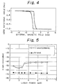
- Fig. 4 shows the Kerr hysteresis curve of the alloy layer, in which the abscissa represents an external magnetic field applied perpendicularly to the main surface of the layer and the ordinate represents a relative value of the Kerr rotation angle with the saturated Kerr rotation angle. The remanence that is a ratio of the saturated Kerr rotation angle to the residual Kerr rotation angle was 0.95.
- a composite target of a Co target (100 nm diameter) on which Pt, Re and Ru chips were placed was inserted and a silicon substrate having a 20 nm thick AlSiN amorphous dielectric layer thereon was disposed on a water cooled table which faced the composite target.
- the CoPtReRu alloy layer had a composition of 48.8 atom% Co, 26.5 atom% Pt, 9.1 atom% Re and 15.6 atom% Ru, a saturated Kerr rotation angle at a wavelength of 400 nm of 0.23 deg, and an effective magnetic anisotropy energy of 1.2 ⁇ 105 erg/cc.
- the squareness ratio was 0.95.
- a magneto-optical recording medium was prepared by successively depositing, on a grooved polycarbonate disc having a diameter of 130 mm, a thickness of 1.2 mm and a track pitch of 1.0 ⁇ m, an AlSiN amorphous dielectric layer 20 mm thick, a CoPtRe alloy magneto-optical layer 10 nm thick, an AlSiN amorphous dielectric layer 50 nm thick, and an Al95Au5 alloy layer 25 nm thick.
- the CoPtRe recording layer had a composition of 72.9 atom% Co, 20.3 atom% Pt and 6.8 atom% Re.
- Magneto-optical recording was performed on this magneto-optical recording disc.
- the laser used for recording and reproducing was a laser beam having a wavelength of 533 nm, the linear speed was 5.56 m/sec, the recording frequency was 1.39 MHz, the recording external magnetic field was 200 Oe, and the reproducing laser power was 1.5 mW.
- Fig. 5 shows the recording and reproducing characteristics of the magneto-optical recording disc.
- the abscissa represents the power of the recording laser beam and the ordinate represents the levels of the carrier (c) and noise (N).
- the recording and reproducing could be performed at a laser wavelength of 533 nm and the maximum carrier to noise ratio was 25.4 dB.
Landscapes
- Chemical & Material Sciences (AREA)
- Inorganic Chemistry (AREA)
- Engineering & Computer Science (AREA)
- Power Engineering (AREA)
- Thin Magnetic Films (AREA)
Applications Claiming Priority (4)
| Application Number | Priority Date | Filing Date | Title |
|---|---|---|---|
| JP167551/92 | 1992-06-25 | ||
| JP04167551A JP3113069B2 (ja) | 1992-06-25 | 1992-06-25 | 磁気記録膜、磁気記録媒体、および光磁気記録媒体 |
| JP258233/92 | 1992-09-28 | ||
| JP25823392A JP3183965B2 (ja) | 1992-09-28 | 1992-09-28 | 磁気記録膜、磁気記録媒体、および光磁気記録媒体 |
Publications (2)
| Publication Number | Publication Date |
|---|---|
| EP0576292A2 true EP0576292A2 (fr) | 1993-12-29 |
| EP0576292A3 EP0576292A3 (en) | 1994-05-11 |
Family
ID=26491557
Family Applications (1)
| Application Number | Title | Priority Date | Filing Date |
|---|---|---|---|
| EP19930304971 Withdrawn EP0576292A3 (en) | 1992-06-25 | 1993-06-25 | Magneto-optical layer and magneto-optical recording medium |
Country Status (4)
| Country | Link |
|---|---|
| EP (1) | EP0576292A3 (fr) |
| KR (1) | KR100194132B1 (fr) |
| CA (1) | CA2098950A1 (fr) |
| TW (3) | TW257858B (fr) |
Cited By (1)
| Publication number | Priority date | Publication date | Assignee | Title |
|---|---|---|---|---|
| EP0911821A4 (fr) * | 1996-07-11 | 2001-05-23 | Toyota Motor Co Ltd | Support d'enregistrement magneto-optique et dispositif d'enregistrement magneto-optique utilisant ce support |
Families Citing this family (1)
| Publication number | Priority date | Publication date | Assignee | Title |
|---|---|---|---|---|
| TWI642800B (zh) * | 2017-10-03 | 2018-12-01 | 光洋應用材料科技股份有限公司 | 鈷鉑錸基濺鍍靶材、其製法及磁記錄層 |
Family Cites Families (3)
| Publication number | Priority date | Publication date | Assignee | Title |
|---|---|---|---|---|
| EP0449252A1 (fr) * | 1990-03-29 | 1991-10-02 | Mitsui Petrochemical Industries, Ltd. | Milieu magnéto-optique d'enregistrement |
| JPH04186706A (ja) * | 1990-11-21 | 1992-07-03 | Hitachi Ltd | 光磁気記録膜とその製造法 |
| DE69223468T2 (de) * | 1991-09-03 | 1998-06-04 | Koninkl Philips Electronics Nv | Magnetooptisches Aufzeichnungsmedium |
-
1993
- 1993-06-22 CA CA002098950A patent/CA2098950A1/fr not_active Abandoned
- 1993-06-24 KR KR1019930011569A patent/KR100194132B1/ko not_active Expired - Fee Related
- 1993-06-25 TW TW084101473A patent/TW257858B/zh active
- 1993-06-25 TW TW084101474A patent/TW257859B/zh active
- 1993-06-25 EP EP19930304971 patent/EP0576292A3/en not_active Withdrawn
- 1993-06-25 TW TW082105083A patent/TW253050B/zh active
Cited By (1)
| Publication number | Priority date | Publication date | Assignee | Title |
|---|---|---|---|---|
| EP0911821A4 (fr) * | 1996-07-11 | 2001-05-23 | Toyota Motor Co Ltd | Support d'enregistrement magneto-optique et dispositif d'enregistrement magneto-optique utilisant ce support |
Also Published As
| Publication number | Publication date |
|---|---|
| EP0576292A3 (en) | 1994-05-11 |
| TW257858B (fr) | 1995-09-21 |
| CA2098950A1 (fr) | 1993-12-26 |
| TW257859B (fr) | 1995-09-21 |
| KR940006096A (ko) | 1994-03-23 |
| KR100194132B1 (ko) | 1999-06-15 |
| TW253050B (fr) | 1995-08-01 |
Similar Documents
| Publication | Publication Date | Title |
|---|---|---|
| US8133332B2 (en) | Method for preparing FePt media at low ordering temperature and fabrication of exchange coupled composite media and gradient anisotropy media for magnetic recording | |
| US5484491A (en) | Ferromagnetic film | |
| EP0717422A1 (fr) | Film mince à accouplement d'interchange et élément magnétorésistif | |
| EP0297776B1 (fr) | Films minces et doux magnétiques | |
| US9899050B2 (en) | Multiple layer FePt structure | |
| CA1315612C (fr) | Support d'enregistrement magnetique perpendiculaire | |
| EP0564188B1 (fr) | Film avec magnétisation perpendiculaire, procédé de sa préparation et milieu d'enregistrement magnétique utilisant ce film | |
| EP0304927B1 (fr) | Milieu d'enregistrement magnétique perpendiculaire | |
| US5851582A (en) | Magnetic recording medium and process for producing the same | |
| EP0586142B1 (fr) | Films magnétiques pour l'enregistrement perpendiculaire, films multi-couches pour la conversion en films magnétiques pour l'enregistrement perpendiculaire et procédé pour la production de films magnétiques pour l'enregistrement perpendiculaire à partir des dits films multi-couches. | |
| US5626973A (en) | Magneto-optical layer and magneto-optical recording medium | |
| US5628953A (en) | Process for producing perpendicular magnetic film | |
| EP0492584B1 (fr) | Support d'enregistrement magnétooptique | |
| EP0576292A2 (fr) | Couche magnéto-optique et milieu d'enregistrement magnéto-optique | |
| US5413868A (en) | Perpendicular magnetic recording medium comprising a magnetic thin film of cobalt, palladium, chromium and oxygen | |
| JP3108637B2 (ja) | 軟磁性薄膜の製造方法 | |
| JPH0757312A (ja) | 光磁気薄膜および光磁気記録媒体 | |
| JP2526615B2 (ja) | 光磁気記録媒体 | |
| EP1887568B1 (fr) | Support d'enregistrement magnétique assisté et procédé de fabrication correspondant | |
| JPH0757311A (ja) | 光磁気薄膜および光磁気記録媒体 | |
| JPH0757310A (ja) | 光磁気薄膜および光磁気記録媒体 | |
| JPH0757309A (ja) | 光磁気薄膜および光磁気記録媒体 | |
| JP3113069B2 (ja) | 磁気記録膜、磁気記録媒体、および光磁気記録媒体 | |
| JP3532607B2 (ja) | 磁気抵抗効果素子 | |
| JPH07141708A (ja) | 光磁気薄膜および光磁気記録媒体 |
Legal Events
| Date | Code | Title | Description |
|---|---|---|---|
| PUAI | Public reference made under article 153(3) epc to a published international application that has entered the european phase |
Free format text: ORIGINAL CODE: 0009012 |
|
| AK | Designated contracting states |
Kind code of ref document: A2 Designated state(s): DE FR GB NL |
|
| PUAL | Search report despatched |
Free format text: ORIGINAL CODE: 0009013 |
|
| AK | Designated contracting states |
Kind code of ref document: A3 Designated state(s): DE FR GB NL |
|
| 17P | Request for examination filed |
Effective date: 19940628 |
|
| 17Q | First examination report despatched |
Effective date: 19961223 |
|
| STAA | Information on the status of an ep patent application or granted ep patent |
Free format text: STATUS: THE APPLICATION IS DEEMED TO BE WITHDRAWN |
|
| 18D | Application deemed to be withdrawn |
Effective date: 19990602 |