EP0576355A1 - Umschaltlufteinlassklappen für ein Kombitriebwerk mit zwei unterschiedlichen Betriebsweisen - Google Patents
Umschaltlufteinlassklappen für ein Kombitriebwerk mit zwei unterschiedlichen Betriebsweisen Download PDFInfo
- Publication number
- EP0576355A1 EP0576355A1 EP93401611A EP93401611A EP0576355A1 EP 0576355 A1 EP0576355 A1 EP 0576355A1 EP 93401611 A EP93401611 A EP 93401611A EP 93401611 A EP93401611 A EP 93401611A EP 0576355 A1 EP0576355 A1 EP 0576355A1
- Authority
- EP
- European Patent Office
- Prior art keywords
- flaps
- vein
- internal
- peripheral
- central
- Prior art date
- Legal status (The legal status is an assumption and is not a legal conclusion. Google has not performed a legal analysis and makes no representation as to the accuracy of the status listed.)
- Granted
Links
Images

Classifications
-
- F—MECHANICAL ENGINEERING; LIGHTING; HEATING; WEAPONS; BLASTING
- F02—COMBUSTION ENGINES; HOT-GAS OR COMBUSTION-PRODUCT ENGINE PLANTS
- F02K—JET-PROPULSION PLANTS
- F02K7/00—Plants in which the working fluid is used in a jet only, i.e. the plants not having a turbine or other engine driving a compressor or a ducted fan; Control thereof
- F02K7/10—Plants in which the working fluid is used in a jet only, i.e. the plants not having a turbine or other engine driving a compressor or a ducted fan; Control thereof characterised by having ram-action compression, i.e. aero-thermo-dynamic-ducts or ram-jet engines
- F02K7/16—Composite ram-jet/turbo-jet engines
-
- F—MECHANICAL ENGINEERING; LIGHTING; HEATING; WEAPONS; BLASTING
- F02—COMBUSTION ENGINES; HOT-GAS OR COMBUSTION-PRODUCT ENGINE PLANTS
- F02C—GAS-TURBINE PLANTS; AIR INTAKES FOR JET-PROPULSION PLANTS; CONTROLLING FUEL SUPPLY IN AIR-BREATHING JET-PROPULSION PLANTS
- F02C7/00—Features, components parts, details or accessories, not provided for in, or of interest apart form groups F02C1/00 - F02C6/00; Air intakes for jet-propulsion plants
- F02C7/04—Air intakes for gas-turbine plants or jet-propulsion plants
- F02C7/042—Air intakes for gas-turbine plants or jet-propulsion plants having variable geometry
Definitions
- the invention relates to a combined reactor provided with means for switching between two operating states such as operation in a turbojet engine and operation in a ramjet.
- Operation in a turbojet engine is preferred up to an airplane speed of about four times the speed of sound (Mach 4), but it is necessary to switch to ramjet mode to obtain even higher speeds (up to Mach 7 or Mach 8).
- the air then reaches a very high temperature, it must be made to bypass the gas turbine which mainly constitutes the turbojet engine and that is why the reactor vein is divided over a section of its length between a central turbojet engine vein. where the turbine is located and a peripheral vein surrounding the previous one where the ramjet burners are located. It is however necessary to provide means for obstructing one or the other of the two veins in order to guide all the air in the vein associated with the chosen operation.
- a cone located in the center of the central vein and movable in translation along the axis of the reactor.
- the obstruction of the central vein is carried out if it is constituted with a narrowed entry: the cone comes to touch its outline when it is advanced.
- a flap system is used to obstruct or clear the peripheral vein.
- the invention relates to an improvement of this kind of device and has in particular the advantages of allowing better guiding the air in the chosen vein as well in one mode as in the other, without the means of obstruction hindering the flow in the open vein.
- the reactor therefore comprises obstructing means which consist of internal flaps articulated in the center of the central vein and external flaps articulated between the central vein and the peripheral vein, the internal flaps having a substantially axial orientation in a first mode of operation of the reactor such as the turbojet mode, the external flaps then obstructing the peripheral vein, and the internal and external flaps that can be turned and deployed so as to join by ends opposite their joints and to take a common cone arrangement obstructing the central vein and diverting the gases towards the peripheral vein, in the other operating mode such as the ramjet mode.
- obstructing means consist of internal flaps articulated in the center of the central vein and external flaps articulated between the central vein and the peripheral vein, the internal flaps having a substantially axial orientation in a first mode of operation of the reactor such as the turbojet mode, the external flaps then obstructing the peripheral vein, and the internal and external flaps that can be turned and deployed so as to join by ends opposite their joints and to take a common cone arrangement o
- the interior flaps prefferably be composed of concentric layers hinged together between the joint and an actuation means, a stop device between the parts being provided to limit their angular movements.
- These devices can consist of rods provided with clearance connections between consecutive articulated parts.
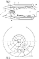
- the reactor of FIG. 1 comprises an air inlet handle 1 which is then divided to form a central vein 2 and a peripheral vein 3 concentric with the previous one.
- the central vein 2 houses a gas turbine 4 which constitutes the essential element of the turbo-reactor, and the peripheral vein 3 bypasses the gas turbine 4 and only joins the central vein 2 at the gas outlet nozzle 35. It is equipped with 36 burners at this location.
- the gas turbine 4 has an inlet cone 5 in the center in the direction of the handle 1.
- the air bypasses it before moving towards the blades 6 of the compressor.
- the central vein 2 is limited to the outside by a circular wall 7 that external flaps 8, oriented in the axial direction and together forming a cylinder, extend in operation of the turbojet engine. They then close the entry of the peripheral vein 3 by touching by their free end 9, opposite to a joint 10 at the edge of the circular wall 7, the external wall 11 which delimits the air inlet handle 1.
- the air inlet cone 5 is essentially (see Figures 2 and 3) composed of interior flaps which can be distinguished three successive and concentric layers: tip flaps 12 connected by joints 13 at the end of a fixed central axis 14 and linked to the gas turbine 4, intermediate flaps 15 and base flaps 16.
- Hinges 17 unite one of the ends of the intermediate flaps 15 at the ends of the tip flaps 12 which are opposite to the hinges 13, and hinges 18 similarly connect one end of the base flaps 16 (their opposite end 19 being free) at the ends of the intermediate flaps 15 opposite the articulations 13.
- the internal flaps 12, 15 and 16 carry crank supports, respectively, 20, 21 and 22 on their face oriented towards the axis 14.
- rods 23, 24 and 25 are articulated respectively to crank pins of the supports 20 and 21, to crank pins of the supports 21 and 22 and to crank pins of the supports 22 and shelves 26 secured to the rod of cylinders 27 parallel to the axis 14, arranged immediately around it and whose cylinder is linked to the gas turbine 4.
- the rods 23 and 24 are provided with shackles 28 whose hole has a wide game compared to the pin which is engaged.
- the internal flaps 12, 15 and 16 can rotate relative to each other within angular limits defined by sets of links 23 and 24. There are two stop positions: in one of them.
- the jacks 27 have the rod retracted and the internal flaps 12, 15 and 16 form a surface whose substantially conical shape tapers with an axial orientation more and more pronounced to become roughly cylindrical towards the rear, where the end 19 is connected to the wall 29 which delimits inside the central vein 3, almost extending it.
- the external flaps 8 extend the circular wall 7, are connected to the external wall 11 and close the entrance to the peripheral vein 3. It can be seen that the air is guided with ease in the central vein 2 thanks to the 'absence of angles and sudden changes in section at the transition between the handle 1 and the central vein 2.
Landscapes
- Engineering & Computer Science (AREA)
- Chemical & Material Sciences (AREA)
- Combustion & Propulsion (AREA)
- Mechanical Engineering (AREA)
- General Engineering & Computer Science (AREA)
- Physics & Mathematics (AREA)
- Geometry (AREA)
- Structures Of Non-Positive Displacement Pumps (AREA)
- Control Of Turbines (AREA)
- Physical Or Chemical Processes And Apparatus (AREA)
Applications Claiming Priority (2)
| Application Number | Priority Date | Filing Date | Title |
|---|---|---|---|
| FR929207712A FR2692938B1 (fr) | 1992-06-24 | 1992-06-24 | Réacteur combiné et muni de moyens de commutation entre deux états de fonctionnement. |
| FR9207712 | 1992-06-24 |
Publications (2)
| Publication Number | Publication Date |
|---|---|
| EP0576355A1 true EP0576355A1 (de) | 1993-12-29 |
| EP0576355B1 EP0576355B1 (de) | 1995-11-29 |
Family
ID=9431110
Family Applications (1)
| Application Number | Title | Priority Date | Filing Date |
|---|---|---|---|
| EP93401611A Expired - Lifetime EP0576355B1 (de) | 1992-06-24 | 1993-06-23 | Umschaltlufteinlassklappen für ein Kombitriebwerk mit zwei unterschiedlichen Betriebsweisen |
Country Status (5)
| Country | Link |
|---|---|
| US (1) | US5343695A (de) |
| EP (1) | EP0576355B1 (de) |
| JP (1) | JP2967016B2 (de) |
| DE (1) | DE69300898T2 (de) |
| FR (1) | FR2692938B1 (de) |
Families Citing this family (9)
| Publication number | Priority date | Publication date | Assignee | Title |
|---|---|---|---|---|
| US5706650A (en) * | 1995-08-09 | 1998-01-13 | United Technologies Corporation | Vectoring nozzle using injected high pressure air |
| JP2756946B2 (ja) * | 1996-02-02 | 1998-05-25 | 川崎重工業株式会社 | 飛翔体 |
| WO1998037323A1 (fr) * | 1997-02-25 | 1998-08-27 | Anatoly Grigorievich Korolev | Moteur magneto-gazo-dynamique combine a statoreacteur |
| RU2162539C1 (ru) * | 1999-05-05 | 2001-01-27 | Александр Евгеньевич Яшин | Комбинированная двигательная установка для летательных аппаратов |
| RU2278986C1 (ru) * | 2005-02-04 | 2006-06-27 | Борис Федорович Кочетков | Комбинированный воздушно-реактивный двигатель |
| US8429893B2 (en) * | 2009-08-11 | 2013-04-30 | Northrop Grumman Corporation | Airflow modulation for dual mode combined cycle propulsion systems |
| US9109539B2 (en) | 2010-12-27 | 2015-08-18 | Rolls-Royce North American Technologies, Inc. | Turbine based combined cycle engine |
| CN109281763B (zh) * | 2018-07-30 | 2021-01-19 | 南京航空航天大学 | 一种基于内流双涵调节控制的组合动力进气道 |
| US11261791B2 (en) | 2019-02-25 | 2022-03-01 | Rolls-Royce Corporation | Hybrid propulsion cooling system |
Citations (5)
| Publication number | Priority date | Publication date | Assignee | Title |
|---|---|---|---|---|
| US3016694A (en) * | 1958-05-13 | 1962-01-16 | Westinghouse Electric Corp | Combination turbojet and ramjet engine |
| GB2027813A (en) * | 1978-08-09 | 1980-02-27 | Mtu Muenchen Gmbh | Turbomachine having variable flow divider |
| DE2917303A1 (de) * | 1979-04-28 | 1980-10-30 | Dornier Gmbh | Antriebsanlage fuer luftfahrzeuge |
| EP0358347A2 (de) * | 1988-09-09 | 1990-03-14 | British Aerospace Public Limited Company | Verstellbarer Lufteinlass für Raumfahrzeuge |
| FR2653177A1 (fr) * | 1989-10-13 | 1991-04-19 | Mtu Muenchen Gmbh | Turbo-statoreacteur equipant des avions pour vol sub et/ou hypersonique. |
Family Cites Families (2)
| Publication number | Priority date | Publication date | Assignee | Title |
|---|---|---|---|---|
| DE3811614C1 (de) * | 1988-04-07 | 1989-05-18 | Messerschmitt-Boelkow-Blohm Gmbh, 8012 Ottobrunn, De | |
| DE3912330A1 (de) * | 1989-04-14 | 1990-10-18 | Mtu Muenchen Gmbh | Integriertes turbo-staustrahltriebwerk |
-
1992
- 1992-06-24 FR FR929207712A patent/FR2692938B1/fr not_active Expired - Fee Related
-
1993
- 1993-06-14 US US08/075,879 patent/US5343695A/en not_active Expired - Lifetime
- 1993-06-23 EP EP93401611A patent/EP0576355B1/de not_active Expired - Lifetime
- 1993-06-23 DE DE69300898T patent/DE69300898T2/de not_active Expired - Lifetime
- 1993-06-24 JP JP5153935A patent/JP2967016B2/ja not_active Expired - Fee Related
Patent Citations (5)
| Publication number | Priority date | Publication date | Assignee | Title |
|---|---|---|---|---|
| US3016694A (en) * | 1958-05-13 | 1962-01-16 | Westinghouse Electric Corp | Combination turbojet and ramjet engine |
| GB2027813A (en) * | 1978-08-09 | 1980-02-27 | Mtu Muenchen Gmbh | Turbomachine having variable flow divider |
| DE2917303A1 (de) * | 1979-04-28 | 1980-10-30 | Dornier Gmbh | Antriebsanlage fuer luftfahrzeuge |
| EP0358347A2 (de) * | 1988-09-09 | 1990-03-14 | British Aerospace Public Limited Company | Verstellbarer Lufteinlass für Raumfahrzeuge |
| FR2653177A1 (fr) * | 1989-10-13 | 1991-04-19 | Mtu Muenchen Gmbh | Turbo-statoreacteur equipant des avions pour vol sub et/ou hypersonique. |
Also Published As
| Publication number | Publication date |
|---|---|
| JP2967016B2 (ja) | 1999-10-25 |
| US5343695A (en) | 1994-09-06 |
| EP0576355B1 (de) | 1995-11-29 |
| DE69300898T2 (de) | 1996-05-23 |
| FR2692938A1 (fr) | 1993-12-31 |
| DE69300898D1 (de) | 1996-01-11 |
| JPH0658203A (ja) | 1994-03-01 |
| FR2692938B1 (fr) | 1994-09-02 |
Similar Documents
| Publication | Publication Date | Title |
|---|---|---|
| EP0315522B1 (de) | Schubdüse mit Schubumkehrvorrichtung mittels Klappen und mit veränderbarem Querschnitt | |
| CA2225608C (fr) | Inverseur de poussee de turboreacteur a double flux a coquilles aval | |
| EP3415749B1 (de) | Gondel mit schubumkehrsystem, das begrenzte aerodynamische störungen aufweist | |
| EP0365425A1 (de) | Schubumkehrvorrichtung mit im Drehpunkt gelagerten Schwenkklappen | |
| CA2850704A1 (fr) | Inverseur de poussee a grilles mobiles et capot mobile monobloc | |
| EP0809010B1 (de) | Schubumkehrvorrichtung für ein Zweikreistriebwerk mit Klappen am Triebwerksgehäuse | |
| EP0848153A1 (de) | Schubumkehrvorrichtung für ein Strahltriebwerk mit Umlenkklappen und an der festen Trägerstruktur behalteten Leitflächen | |
| EP0882881B1 (de) | Schubumkehrvorrichtung für ein Strahltriebwerk dessen Umkehrklappen mit optimal entfaltbaren Leitflächen versehen sind | |
| CA2619561C (fr) | Melangeur de flux a section variable pour turboreacteur a double flux d'avion supersonique | |
| FR3068081A1 (fr) | Systeme d'inverseur de poussee presentant des perturbations aerodynamiques limitees | |
| EP0777045A1 (de) | Schubumkehrvorrichtung mit Klappen und an dem Hinterteil verbundenen Hilfsklappen | |
| EP0576355B1 (de) | Umschaltlufteinlassklappen für ein Kombitriebwerk mit zwei unterschiedlichen Betriebsweisen | |
| EP1020631B1 (de) | Strahltriebdüse mit integrierter Schubumkehrvorrichtung | |
| FR2768773A1 (fr) | Inverseur de poussee de turboreacteur a coquilles internes | |
| FR2766522A1 (fr) | Inverseur de poussee de turbosoufflante a obstacle a guidage axial lies au capot primaire | |
| CA2286381A1 (fr) | Inverseur de poussee de turboreacteur a obstacles aval | |
| CA2152883C (fr) | Inverseur de poussee de turboreacteur a double flux, a obstacles lies au capot primaire | |
| EP1045130B1 (de) | Allseitig schwenkbare konvergente - divergente Schubdüse mit einem kardanischen Bedienungsring | |
| FR2858021A1 (fr) | Tuyere de moteur a turbine | |
| EP0807752A1 (de) | Schubumkehrvorrichtung mit beweglichen Auskleidungen in den Klappen | |
| EP3947950B1 (de) | Tür für schubumkehrvorrichtung einer flugzeugantriebsanordnung mit einer flexiblen ablenkplatte | |
| FR2672339A1 (fr) | Inverseur de poussee. | |
| FR2734323A1 (fr) | Perfectionnement aux tuyeres bidimensionnelles comportant en particulier un deviateur de jet | |
| FR2651536A1 (fr) | Charniere de tuyere d'echappement et moteur a turbine a gaz comportant une tuyere equipee d'une telle charniere. | |
| EP1653073B1 (de) | Schubdüse mit veränderlichem Querschnitt für Turbomaschine |
Legal Events
| Date | Code | Title | Description |
|---|---|---|---|
| PUAI | Public reference made under article 153(3) epc to a published international application that has entered the european phase |
Free format text: ORIGINAL CODE: 0009012 |
|
| 17P | Request for examination filed |
Effective date: 19930705 |
|
| AK | Designated contracting states |
Kind code of ref document: A1 Designated state(s): DE FR GB |
|
| 17Q | First examination report despatched |
Effective date: 19941202 |
|
| GRAA | (expected) grant |
Free format text: ORIGINAL CODE: 0009210 |
|
| AK | Designated contracting states |
Kind code of ref document: B1 Designated state(s): DE FR GB |
|
| REF | Corresponds to: |
Ref document number: 69300898 Country of ref document: DE Date of ref document: 19960111 |
|
| GBT | Gb: translation of ep patent filed (gb section 77(6)(a)/1977) |
Effective date: 19960106 |
|
| PLBE | No opposition filed within time limit |
Free format text: ORIGINAL CODE: 0009261 |
|
| STAA | Information on the status of an ep patent application or granted ep patent |
Free format text: STATUS: NO OPPOSITION FILED WITHIN TIME LIMIT |
|
| 26N | No opposition filed | ||
| REG | Reference to a national code |
Ref country code: GB Ref legal event code: IF02 |
|
| REG | Reference to a national code |
Ref country code: FR Ref legal event code: TP Ref country code: FR Ref legal event code: CD |
|
| REG | Reference to a national code |
Ref country code: FR Ref legal event code: CD |
|
| PGFP | Annual fee paid to national office [announced via postgrant information from national office to epo] |
Ref country code: GB Payment date: 20110606 Year of fee payment: 19 |
|
| PGFP | Annual fee paid to national office [announced via postgrant information from national office to epo] |
Ref country code: DE Payment date: 20110606 Year of fee payment: 19 |
|
| REG | Reference to a national code |
Ref country code: GB Ref legal event code: 732E Free format text: REGISTERED BETWEEN 20120517 AND 20120523 |
|
| PGFP | Annual fee paid to national office [announced via postgrant information from national office to epo] |
Ref country code: FR Payment date: 20120621 Year of fee payment: 20 |
|
| GBPC | Gb: european patent ceased through non-payment of renewal fee |
Effective date: 20120623 |
|
| REG | Reference to a national code |
Ref country code: DE Ref legal event code: R119 Ref document number: 69300898 Country of ref document: DE Effective date: 20130101 |
|
| PG25 | Lapsed in a contracting state [announced via postgrant information from national office to epo] |
Ref country code: GB Free format text: LAPSE BECAUSE OF NON-PAYMENT OF DUE FEES Effective date: 20120623 Ref country code: DE Free format text: LAPSE BECAUSE OF NON-PAYMENT OF DUE FEES Effective date: 20130101 |