EP0576399A1 - Méthode de commande d'un système de traitement photographique et système de traitement photographique - Google Patents
Méthode de commande d'un système de traitement photographique et système de traitement photographique Download PDFInfo
- Publication number
- EP0576399A1 EP0576399A1 EP93810435A EP93810435A EP0576399A1 EP 0576399 A1 EP0576399 A1 EP 0576399A1 EP 93810435 A EP93810435 A EP 93810435A EP 93810435 A EP93810435 A EP 93810435A EP 0576399 A1 EP0576399 A1 EP 0576399A1
- Authority
- EP
- European Patent Office
- Prior art keywords
- film
- processing
- photographic
- copy
- processor
- Prior art date
- Legal status (The legal status is an assumption and is not a legal conclusion. Google has not performed a legal analysis and makes no representation as to the accuracy of the status listed.)
- Granted
Links
Images


Classifications
-
- G—PHYSICS
- G03—PHOTOGRAPHY; CINEMATOGRAPHY; ANALOGOUS TECHNIQUES USING WAVES OTHER THAN OPTICAL WAVES; ELECTROGRAPHY; HOLOGRAPHY
- G03D—APPARATUS FOR PROCESSING EXPOSED PHOTOGRAPHIC MATERIALS; ACCESSORIES THEREFOR
- G03D15/00—Apparatus for treating processed material
- G03D15/001—Counting; Classifying; Marking
- G03D15/005—Order systems, e.g. printsorter
-
- G—PHYSICS
- G03—PHOTOGRAPHY; CINEMATOGRAPHY; ANALOGOUS TECHNIQUES USING WAVES OTHER THAN OPTICAL WAVES; ELECTROGRAPHY; HOLOGRAPHY
- G03B—APPARATUS OR ARRANGEMENTS FOR TAKING PHOTOGRAPHS OR FOR PROJECTING OR VIEWING THEM; APPARATUS OR ARRANGEMENTS EMPLOYING ANALOGOUS TECHNIQUES USING WAVES OTHER THAN OPTICAL WAVES; ACCESSORIES THEREFOR
- G03B27/00—Photographic printing apparatus
- G03B27/32—Projection printing apparatus, e.g. enlarger, copying camera
- G03B27/46—Projection printing apparatus, e.g. enlarger, copying camera for automatic sequential copying of different originals, e.g. enlargers, roll film printers
- G03B27/462—Projection printing apparatus, e.g. enlarger, copying camera for automatic sequential copying of different originals, e.g. enlargers, roll film printers in enlargers, e.g. roll film printers
-
- G—PHYSICS
- G03—PHOTOGRAPHY; CINEMATOGRAPHY; ANALOGOUS TECHNIQUES USING WAVES OTHER THAN OPTICAL WAVES; ELECTROGRAPHY; HOLOGRAPHY
- G03D—APPARATUS FOR PROCESSING EXPOSED PHOTOGRAPHIC MATERIALS; ACCESSORIES THEREFOR
- G03D13/00—Processing apparatus or accessories therefor, not covered by groups G11B3/00 - G11B11/00
- G03D13/003—Film feed or extraction in development apparatus
-
- G—PHYSICS
- G03—PHOTOGRAPHY; CINEMATOGRAPHY; ANALOGOUS TECHNIQUES USING WAVES OTHER THAN OPTICAL WAVES; ELECTROGRAPHY; HOLOGRAPHY
- G03D—APPARATUS FOR PROCESSING EXPOSED PHOTOGRAPHIC MATERIALS; ACCESSORIES THEREFOR
- G03D13/00—Processing apparatus or accessories therefor, not covered by groups G11B3/00 - G11B11/00
- G03D13/007—Processing control, e.g. test strip, timing devices
-
- G—PHYSICS
- G03—PHOTOGRAPHY; CINEMATOGRAPHY; ANALOGOUS TECHNIQUES USING WAVES OTHER THAN OPTICAL WAVES; ELECTROGRAPHY; HOLOGRAPHY
- G03B—APPARATUS OR ARRANGEMENTS FOR TAKING PHOTOGRAPHS OR FOR PROJECTING OR VIEWING THEM; APPARATUS OR ARRANGEMENTS EMPLOYING ANALOGOUS TECHNIQUES USING WAVES OTHER THAN OPTICAL WAVES; ACCESSORIES THEREFOR
- G03B2206/00—Systems for exchange of information between different pieces of apparatus, e.g. for exchanging trimming information, for photo finishing
- G03B2206/004—Systems for exchange of information between different pieces of apparatus, e.g. for exchanging trimming information, for photo finishing using markings on the photographic material, e.g. to indicate pseudo-panoramic exposure
Definitions
- the invention relates to a method for operating a photographic processing system according to the preamble of patent claim 1. Furthermore, the invention also relates to a photographic processing system according to the preamble of patent claim 19.
- the film material or the copy material is wound on individual processing machines on rolls and is usually transported by hand.
- the administration and transport of the film rolls or the copy material rolls and the job bags is personnel-intensive and often represents a source of errors when individual film rolls, paper rolls or job bag bundles are mixed up.
- the rolls are made as large as possible.
- a film roll or a copy material roll is only transported to the next processing station when it is full. This results in long lead times for the individual customer orders.
- Film and copy material processors work most economically if they work at constant speed and are constantly loaded with film or copy material. If the leading stations work slower than the respective processors, due to the fact that the throughput times (development times) of the undeveloped exposed film material or the corresponding copying material are fixed by the selected process, a sufficient number of supply rolls must be started before starting the processors be produced to ensure continuous operation of the processors. In this way, the throughput time of a customer order through the photographic processing system is further extended unnecessarily. In addition, the necessary planning effort with regard to logistics and role management is further increased.
- the object of the present invention is therefore to improve a photographic processing system and a method for operating such a system in such a way that the overall processing speed is increased and the customer's request for a shorter processing time can be taken into account.
- possible sources of error are to be eliminated and the planning effort with regard to process logistics is to be simplified.
- a plant and an operating method are to be created which allow the processing sequences to be largely automated and the use of personnel to be kept as low as possible.
- Economic constant-speed processors are to be used, which are structurally simpler and less prone to errors and require less investment than the film or copier material processors with variable speed and variable throughput distance.
- customer orders should be able to be processed inexpensively at high speed.
- the invention provides a method for operating a photographic processing system, which allows the throughput time of a customer order to be optimized through the system.
- the photographic processing system according to the invention is preferably of modular construction and comprises various processing modules for processing exposed photographic film material and / or photographic copying material.
- the individual processing modules each have one or more processing stations and, as required, the exposed film material and / or the photographic copying material pass through them one after the other.
- the operating method according to the invention for the photographic processing system is characterized in particular in that the control of the throughput and processing speeds of the film material and / or the copying material is hierarchically structured in two stages.
- the processing speed of the film material or the copying material in the respective previous processing station depends on the speed a processing station, which must be run through by the film material or the copy material at a predetermined constant speed, locally controlled.
- the various processing modules are connected via signal lines to a higher-level central control unit, with the aid of which the function of the individual processing stations is monitored and the throughput of the film material and / or the copying material is optimized by the photographic processing system.
- the local control in the individual processing modules solves all time-critical operations and tasks automatically and thus allows the optimization to be carried out at the higher-level control level in the central control.
- the local control preferably works on the "master-slave" (master-slave) principle and runs autonomously and fully automatically after the operation of the corresponding processing module has started.
- the processing system comprises, for example, at least one module with a photographic copier and with a copier material processor with an upstream copier material buffer for the development of the exposed copier material, which are connected to one another via signal lines.
- the processing speed of the copying material in the photographic copier is controlled locally with the help of the autonomous local control in accordance with the predetermined constant throughput speed of the copying material processor and the fill level of the copying material buffer.
- the local control of this module ensures that the processing speed of the film material in the film opening and splicing station
- the local constant throughput speed of the film processor and the fill level of the film buffer are controlled locally.
- the photographic processing system preferably has both processing modules described above.
- the module which comprises the photographic copier, is arranged after the film material processor.
- the processing speed of the film material in the film opening and splicing station or the copying material in the photographic copier is controlled in such a way that the fill level of the respective buffer is approximately 80% to approximately 99%.
- brief interruptions in the preceding processing stations can be compensated for, and the respective processor can continue to run at the speed that is predetermined by the selected development process.
- short interruptions in the film opening and splicing station can be compensated in this way, which occur when a splice cannot be carried out correctly right away or when films are identified as damaged or out of type and have to be repaired or eliminated.
- the film opening and splicing station can also be equipped with an automatic film inspection station in which these checking and repair functions are carried out.
- a leader tape is automatically spliced into the end of the respective buffer at the end of the film or copy material, which disconnects the output of the film or copy material processor and is transported back to the entrance of the respective buffer.
- the minimum fill level of the buffer is selected so that the time available until the buffer is completely emptied is in any case sufficient to carry out the splicing process.
- the minimum fill level of the respective buffer is preferably about 5% to about 25% of the maximum fill level, depending on the size of the buffer memory.
- the leader tape is cut off at the beginning of the corresponding buffer, the front end of the transported film or copy material is spliced onto the rear end of the leader tape and the front end of the film is output from the film or copy material processor - or copy material tape again separated from the leader tape and the leader tape wound on a separate roll. It can also be provided that the new front end of the film or copy material tape transported is spliced onto the rear end of the previous film or copy material tape waiting in the station in this case.
- the photographic processing system at the beginning of the respective buffer is equipped with an automatic cutting and splicing device and has at least one docking device above or below the cutting and splicing device for a leader tape, preferably wound on a roll.
- An automatic cutting device and optionally also an automatic splicing device and a docking device for a winding roll for the leader tape are also provided at the exit of the associated processor.
- a docking device for rolls and a winding device for winding up the film or copy material onto the rolls is preferably arranged at the outlet of the film or copy material processor. In this way, the film or copy material output of the respective processor can be wound up on rolls. Rolls of film or copying material are particularly suitable as space-saving memories for large quantities of the material to be processed and allow manual intervention for troubleshooting in a simple manner.
- the central control unit monitors and controls the degree of filling of the film or copy material rolls arranged at the exit of the respective processors, depending on the degree of utilization of the processing stations. This means that, depending on requirements, more or less filled roles are created based on the respective processors.
- the criterion for the degree of filling of the rolls is no longer the transport route or the transport time between the individual stations, which has previously meant that the rolls were always filled as completely as possible and thus the retention time of a customer order in the processing plant was extended unnecessarily.
- the central controller now monitors the degree of utilization of the individual processing modules involved and then controls the degree of filling of the roles. In this way, the speed of the stations involved can be reacted to at short notice.
- the central control unit controls the transport of the rolls as required and the degree of utilization of the processing modules involved, and the transport devices are used as a buffer storage.
- the film material is preferably wound up on rolls at the exit of the photographic copier.
- the central control unit controls the winding process of the film material on the one hand and the winding process of the copy material output from the copy material processor on the other hand in such a way that for each film material roll a copy material roll with associated copies is created, the film roll and the copy material roll having the same sequence of different copy templates or copies.
- the arrangement of the master copies and the associated copies on the corresponding rolls is such that the chronological processing sequence is maintained remains. This means that the copy template first entered into the processing system is on the outside of the roll. The same applies of course to the associated copies.
- the central control unit controls the transport of the film rolls from the photographic copier and the transport of the copy material rolls from the exit of the copy material processor in such a way that assigned film and copy material rolls essentially arrive at the cutting and packaging station at the same time.
- the film material rolls are preferably transported from the photographic copying machine or the copy material rolls from the copying material processor to the cutting and packaging station with the aid of fully automatic transport devices which are operated in a controlled manner by the central control and fulfill the function of transport buffers.
- the central control system sends corresponding signals to the operator (s), for example. These signals can be acoustic signals, but they can also be displayed on a screen, or a combination of both can be provided in order to inform the operator or operators of the required role transport.
- the transport of the order pockets for the film rolls, from which the required order data are taken in the film opening and splicing station is preferably also controlled from the film opening and splicing station via preferably fully automatic transport means to the cutting and packaging module such that the sequence the order pockets correspond to the order of the copy material strips on the copy material rolls that are transported to the cutting and packaging module.
- the individual processing modules and stations transmit information to the central control unit via the signal lines, which preferably allow data to be exchanged in both directions, about a customer order that is currently in the respective station, so that with the help of the central control unit a specific one can be made at any time Customer order can be located within the photographic processing facility.
- the system and the operating method are designed so that the customer order first fed into the photographic processing system also leaves it first in the processed state.
- the central control system preferably registers the position coordinates of the individual copy originals determined in the photographic copier on the film material strip. This data is forwarded from the central control to the cutting and packaging station, where the film material strip is then cut in the right place. In this way, there is no need for a notch device in the photographic copier, which punches markings in the film material strips.
- the central control In the event that the number of the individual copies on the film material strip is also recorded in the photographic copier, for example by reading the extended DX codes arranged on the film material strips, it is also very advantageous to register this information with the central control.
- the data are forwarded from the central control, for example, to the cutting and packaging station, where, for example, the corresponding template number can be printed on the front or on the back of the associated copy (s) using a printer device.
- the control of the photographic processing system according to the invention is hierarchically structured in two stages. Local control is provided for the individual processing modules, which largely autonomously controls all time-critical tasks of the corresponding module. The combination of the stations in the individual processing modules thus autonomously provides certain basic functions. Based on these basic functions, a higher-level central controller can monitor the processing operation in the entire photographic processing system and optimize it with regard to the throughput time and the utilization of the individual stations.
- the photographic copier is included in the optimization of the overall process.
- the photographic copier at the entrance and exit of the photographic copier has docking devices for film material wound or to be wound on rolls, and is at the beginning of the A copying device is provided for at least one cassette containing unexposed photographic copying material wound on a roll.
- the central control can include the use and the utilization of the photographic copier in the optimization.
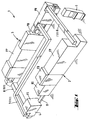
- the processing system is provided with the reference number 1 as a whole and comprises different processing modules 2, 3 and 4. Each processing module in turn comprises at least one processing station, with the aid of which a specific work step is carried out during the processing of a customer order.
- the first processing module 2 comprises a film opening and splicing station OS and a film processor FP arranged thereafter.
- the film opening and splicing station can be expanded by a preferably automatic film inspection station, which performs inspection and repair functions for the film roll material.
- a film buffer FB is integrally connected to the film processor between the film opening and splicing device OS and the film processor FP.
- a second processing module is provided with the reference symbol 3 in FIG.
- the processing module 1 is connected to the first processing module 2 arranged. It comprises a photographic copier (photographic printer) PR and a copying material processor PP arranged after the copier.
- the part of the copy material processor PP which follows the photographic copier PR is designed as a copy material buffer PB.
- the processing device 4 on the output side of the processing system 1 is formed by a cutting and packaging device FS.
- the film processor FP and the copy material processor PP are preferably so-called constant-speed processors with a constant length of the passage of the film material or the copy material through the respective wet part. Such processors are relatively simple in structure, reliable, tried and tested and relatively inexpensive.
- order pockets B with film cartridges C supplied by the customer are usually opened by an operator, the film cartridges C are removed, preferably filled into a film cartridge magazine and placed in the film opening and splicing station OS belonging to the first processing module 2.
- a first preselection of wrong film cartridges is carried out, which the operator and the associated order bag B remove.
- the information about the respective customer order that is usually contained on the order pocket B is communicated to a central control unit 5 (FIGS. 1 and 2) via input means.
- the order pockets B are preferably transported bundled to a packaging station FS. This transport is preferably carried out via automatic transport devices 11, for example via conveyor belts or the like.
- each cartridge is opened and the film is automatically pulled out.
- the film is checked and, if necessary, repaired or eliminated from the process.
- the individual strips of film material, which are found or repaired, are spliced together into a band.
- the film material N is then fed as a long belt over the buffer FB into the film processor FP in order to be developed therein. After development, the film material N is wound out of the film processor FP into a film roll F and cut automatically at a certain fill level.
- the film rolls F are transported along a transport path 6 to the next processing module 3 and at the beginning of the further processing photographic copier PR arranged.
- the still unexposed copying material M is wound onto the copying machine on rolls and fed arranged in cassettes P '. If a cassette P 'is empty, a new filled cassette P' is preferably automatically docked and the new copying material is spliced with the old one, so that the copying machine can be loaded with copying material M practically endlessly.
- the developed film material N is exposed to the copy material M according to the order.
- the exposed copy material M is then fed as an endless band via the copy material buffer PB to the copy material processor PP and developed.
- the exposed and developed copy material M is wound out of the copy material processor PP into a roll P, which is preferably contained in a cassette, and is cut automatically at a certain fill level.
- the film material N is also wound out of the photographic copier PR into a roll F.
- the film material rolls F are transported along the transport path 7 and the copying material cassettes P along the transport path 8 to the last processing module 4, which includes the cutting and packaging station FS. There, the film material N and the copying material M are cut and packed in the order bags B delivered via the transport route 11 in accordance with the assignment.
- the finished customer orders O with the film strips packed in the order pockets B and the desired copies can then be removed.
- transport devices 6, 7, 8 and 11 symbolize transport devices for the film material wound into rolls F, for the copy material rolls P and for the preferably bundled job pockets B from one module to the next.
- the transport devices 6, 7, 8 and 11 are preferably designed for fully automatic operation and can be, for example, conveyor belts, transport lifts and the like, or combinations of different transport devices.
- the photographic processing system described has a number of processing stations, all of which are operated at largely different speeds.
- the processor FP for the film material N and the processor PP for the copy material M must each operate at a predetermined constant speed in order to ensure a uniform development of the film material or the copy material.
- the system of processors can only work in a balanced manner if the ratio of film length to copied material length is constant. However, this is practically never the case and the length of the copying material copied to a corresponding film fluctuates due to the order.
- the copied material length is larger for long image formats or in the case of multiple copies of an original, on the other hand it is smaller for short image formats and in the event that originals are skipped due to their poor quality.
- the average speed of the film material N in the film processor FP or the copy material M in the copy material processor PP is therefore reduced if necessary due to incomplete operation.
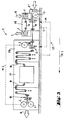
- a local controller LC between the processor and the predecessor machine controls the speed of the predecessor machine as long as there is enough material in the respective intermediate buffer that the processor can work at the required speed, and automatically inserts a leader band L when the fill level of the corresponding buffer reaches a certain value falls below.
- a higher-level central control SC determines the optimum time for changing the film rolls F or the copy material rolls P and for inserting gaps. Local control takes place via simple signal lines between the devices concerned and is integrated in the processing modules.
- the second processing module 3 comprises the photographic copier PR and the copy material processor PP with an upstream copy material buffer PB.
- the material flow in this processing station 3 is indicated by the arrow Pf 1.
- the copy material buffer PB at the beginning of the copy material processor PP is preferably designed as a loop memory.
- a sensor delivers a signal when the buffer is close to its maximum level.
- the copying speed of the copying machine PR is now controlled by the copying material processor PP such that the buffer is preferably always about 80% to about 99% full.
- the buffer content is reduced somewhat and then, after restarting the copying machine PR, brought back to the original filling level by increased copying speed.
- the copying machine for example due to a lack of film material F, can no longer supply exposed copying material M to the processor PP, the minimum level in the copying material buffer PB is undershot and a sensor supplies a further signal.
- a leader tape L is spliced onto the rear end of the copying material M in a cutting and splicing device 9 arranged at the beginning of the buffer PB.
- the leader tape L is unwound from a supply roll arranged above or below the cutting and splicing device 9.
- the copying material M can be transported at a constant speed through the copying material processor PP, in particular through its wet part.
- a further cutting and splicing device 10 is preferably arranged on the output side of the copying material processor PP, the structure of which corresponds to the input side. In principle, a cutting station alone would be sufficient on the output side. There the leader tape L is cut off again from the copying material and preferably wound up on a roll.
- the copying machine PR can again supply copying material M, this is automatically threaded into the transport path to the cutting and splicing station 9. There, the leader tape is cut off and the front end of the new copying material M is spliced onto the rear end of the leader tape L.
- the leader tape L is separated from the developed copy material M and wound up. The roll with the wound leader tape L can be transported back to the input side of the copy material buffer PB, as indicated by the arrow Pf 2 in FIG. 3.
- the front end of the developed new copy material can be spliced onto the rear end of the developed copy material waiting in the station or can be fed to a new take-up roll.
- the principle of the local control LC which has been explained using the example of the second processing module 3 with copier and copier material processor PP, is based on the master-slave principle.
- the processor PP is the Lord
- the previous processing station in this case the PR photocopier
- this principle is implemented in an analogous manner in the first processing module 2, which includes the opening and splicing station OS and the film processor FP.
- the speed of the opening and splicing station OS - the preceding processing station - is controlled by the downstream film processor FP.
- the speed of the preceding opening and splicing station OS is varied depending on the fill level of the fim buffer FB arranged at the input of the film processor FP.
- a leader tape L is used analogously to the procedure described on the basis of the second processing module 3 in order to maintain the continuous operation of the film processor FP.
- the fact that the processor running at a predetermined fixed speed controls the speed of the supply machine according to the master-slave principle and the fact that the device combination can react autonomously to longer interruptions in the material supply allows the use of small, space-saving Buffering between the individual devices.
- the local control LC in the processing stations 2 and 3 solves all time-critical operations and tasks automatically and thus enables the time-critical implementation of the optimization on the higher-level control level in the central control SC.
- the combination of processing stations combined to form a processing module autonomously provides certain basic functions which allow the central control SC to optimize the processing time of a customer order and the utilization of the individual devices.
- the film material N is wound out of the film processor FP on rolls.
- the film rolls F are preferably transported with the aid of automatic transport devices 6 to docking devices for the film rolls F provided on the input side of the photographic copier PR. There, the film material N is preferably automatically threaded into the copier PR. Analog docking devices for film rolls F are provided at the output of the copying machine PR, on which the film material N is wound up again. From the output side of the copier PR, the film rolls are preferably transported to the cutting and packaging station FS by automatic transport devices 7.
- the exposed and developed copy material M is also wound out of the copy material processor PP on rolls, which are preferably arranged in cassettes.
- the copy material cassettes P are finally preferably also transported to the last processing station 4 with the cutting and packaging device FS with the aid of automatic transport devices 8. There, the film material N and the copy material M are cut and packaged in accordance with the assignment. Finally, the finished processed customer orders O can be removed from the last processing station 4.
- the use of film rolls F and copy material rolls P allows simple implementation of long-term storage of variable fill levels.
- these long-term memories can be used very efficiently for the optimization of the lead time of the customer orders O and the utilization of the processing devices.
- the use of automatic transport devices, monitored and controlled by the central control enables the optimizations to be implemented even better.
- the central controller SC monitors and controls the degree of filling of the film or copying material rolls F or P arranged at the output of the respective processors FP or PP, depending on the degree of utilization of the processing modules. This means that, depending on requirements, more or less filled roles F or P are created on the basis of the respective processors FP or PP.
- the criterion for the degree of filling of the rolls is no longer the transport route or the transport time that the operating personnel requires between the individual modules, which has previously led to the rolls always being filled as completely as possible and thus unnecessarily extending the time a customer order is in the processing system has been.
- the central controller SC now monitors the degree of utilization of the individual processing modules 3 and 4 involved and then controls the degree of filling of the roles F and P.
- the transport routes or the transport devices 6 and 7 or 8 provided for the transport of the film rolls F or the copy material rolls P together with the employment possibilities in the target stations fulfill the function of buffer stores, which in this case are designed as roll stores.
- the output side of the respective participating stations FP, PR and PP is counted for the respective transport device 6, 7 and 8, respectively.
- the transport area from the film processor FP to the photographic copier PR is the first transport buffer TB1
- the transport area from the photographic copier PR to the cutting and packaging station FS is the second transport buffer TB2
- the number of film rolls F or of copy material rolls P in the transport buffers TB1 and TB2 or TB3 indicate the filling level of these roll stores. In this way, it is possible to react to fluctuations in the speed of the processing stations involved by creating rolls of greater or smaller fill levels and feeding more or fewer rolls into the respective transport buffers TB1, TB2 or TB3.
- the operation of the photographic processing system 1 according to the invention is thus based on a buffer concept which includes both short-term buffers FB or PB designed as loop memories and transport buffers TB1, TB2 and TB3.
- the film buffer FB catches the short interruptions within the first processing module 2, which can occur if, for example, a splice is not carried out correctly in the opening and splicing station OS or damaged films C or non-type film material N have to be repaired or eliminated.
- the second short-time buffer, the copy material buffer PB catches short interruptions in the production of the copying machine PR in the second processing module 3, which can occur, for example, when changing the film roll, changing the paper roll or simply due to the order that several copies of individual templates have to be made. Even short variations in the processing speed of the copier PR, which arise when skipping unusable originals or multiple copies of originals, are compensated for.
- the first transport buffer TB1 for the film rolls F compensates, in particular, for physical differences in the processing speeds of the film processor FP and the copy material processor PP. However, it also absorbs longer interruptions in the operation of the copier PR due to technical errors.
- the film material N is stored in the second transport buffer TB2 until it can be processed together with the exposed and developed copy material M in the cutting and packaging station FS. This is particularly necessary since the copy material M exposed in the copier PR must first be developed in the copy material processor PP before it can be transported on to the next processing module 4. However, minor interruptions in the operation of the cutting and packaging station FS can also be compensated for.
- the third transport buffer TB3 relates to the exposed and developed copy material M wound on rolls P. It can compensate for interruptions in the operation of the last processing module 4, which can occur when, for example, film rolls are changed or when the operating personnel in the function of the job-related material problems Cutting and packaging station FS must intervene.
- the storage in the buffer stores TB1, TB2 and TB3 and the fill level of the individual roles F and P are monitored and controlled depending on the degree of utilization of the individual stations and optimized with regard to the throughput time.
- the central control unit SC controls, for example, the winding process of the film material N on the one hand and the winding process of the copying material M output of the copying material processor PP on the other hand in such a way that for each film material roll F a copy material roll P with associated copies is created, the film roll F and the Copy material roll P preferably have the same order of different copies or copies.
- a particularly advantageous effect on the throughput time of a customer order is that the order of the negatives on the film roll F is such that the negative first entered into the processing system 1 is arranged extremely on the roll and that the order is retained.
- the central controller SC preferably also controls the transport of the film rolls F from the photographic copier PR and the transport of the copy material rolls P from the output of the copy material processor PP such that assigned film and copy material rolls F and P arrive at the cutting and packaging station FS essentially simultaneously .
- the central control SC is implemented by the central control unit 5, which preferably comprises an electronic computing system with an input and output unit, which is connected to the individual processing modules and stations via serial lines (indicated by the dashed lines SC in FIG. 2).
- the signal lines allow data exchange in both directions.
- the higher-level central control SC controls the basic setting of the individual processing stations, for example the stations are automatically set to the paper format used in each case. It can receive data from the individual stations, process it and forward it to other stations.
- the processing system 1 processes the job data recorded in the opening of the processing system 1 in the opening and splicing station OS, forwards this data to the photographic copier PR in order to ensure that the desired number of copies is made and forwards the data to the cutting and packaging station FS, where the price for the customer order is then printed on the packaging based on this data.
- a very important function is the registration of the position coordinates of the individual copy originals determined in the photographic copier PR on the film material strip N.
- This data is forwarded by the central control SC to the cutting and packaging station FS, where then the film material strip N is cut in the right place.
- a notching device in the photographic copier which stamps markings in the film material strip N.
- this information is also registered by the central control SC.
- the data are forwarded from the central control SC, for example, to the cutting and packaging station FS, where, for example, the corresponding template number can be printed on the front or on the back of the associated copy (s) using a printer device 12.
- the printer device can also be arranged, for example, at the exit of the copy material processor PP.
- the central controller SC forwards the data to it and the number is printed there.
- the central control SC displays and controls the material flow in the processing system 1.
- the individual processing modules transmit information about a customer order currently in the respective module, so that with the help of the central control unit SC, a specific customer order can be localized within the photographic processing system 1 at any time. This is particularly important when problems occur in the processing sequence and, for example, entire orders have to be eliminated. For example, due to poor film material in the photographic copier PR, no copies can be made. It can now be determined very easily on which film material roll F the film strip is located. In the cutting and packaging station FS, the film strip is then recognized and not cut, but rather uncut, along with the associated order bag, is eliminated from the ongoing process.
- the arrangement of the roll buffers which, due to the rewinding processes, change the order of the copy templates on the film material rolls, is selected in such a way that the customer order O that was first fed into it is also used as first leaves in processed condition.
- the central control SC consist primarily in the control of the start-up and shutdown of the individual processing modules and the processing stations arranged in the modules, as well as in the control of the roll size or in the determination of the optimal time for cutting the material in the corresponding station and in the control and optimization of the transport of the rolls from one module to the next.
- FIG. 4a shows the normal operation of the processing installation 1 according to the invention schematically.
- the film cartridges C entered at the entrance to the opening and splicing station OS are opened and the film strips spliced together to form an endless band N and transported on to the film processor FP.
- an order requires the lead time t FP .
- the film material N is cut there and transported to the photographic copier PR.
- the cutting is preferably always carried out at the points between two different films at which a piece of leader tape L has been inserted in the opening and splicing device.
- the exact time for inserting a leader tape L between two films is controlled by the central control SC. To do this, it sums up the data on the film lengths transmitted by the opening and splicing device and compares it with the cutting level ffs. A special marking is attached to this leader tape, which is later recognized by the cutting and splicing station of the film processor FP, which then cuts there.
- leader tape L prevents the film material N from being scratched when it is threaded into a subsequent processing station, for example into the copier PR. In this way, the level ffs subsequently also determines the level of all other film rolls F.
- the photographic copier PR is now not started immediately when the film roll F is docked on the input side, but the central control SC only gives the start command when the next film roll F at the output of the film processor FP has reached a certain reserve level.
- the time span ffr is required for this. In this way, a role is temporarily stored in the first transport buffer TB1. This is indicated in Fig. 4a by the hatched areas.
- the copying material buffer PB is initially filled at the input of the copying material processor PP.
- the central control SC only starts the copy material processor when the buffer PB has reached the desired fill level.
- the throughput time of the copy material M through the copy material buffer PB and the copy material processor PP is given by the time period t pp .
- the developed copy material M is wound onto a roll P at the exit of the copy material processor PP out .
- the copying material M is always cut in such a way that exactly one paper roll P is produced for a film roll F.
- the time for the creation of a copy material roll P output of the copy material processor PP out therefore corresponds approximately to the time for the creation of a film roll F and given by the time period ffs.
- the film material N is wound out of the copying machine PR onto a film roll F, the size of which corresponds to the input side.
- the central control SC now controls the transport to the cutting and packaging station FS in such a way that the copy material roll P arrives via the transport device 8 and the associated film roll F via the transport device 7 at the same time. This can lead to one or more film rolls F being temporarily stored in the second transport buffer TB2, as long as the corresponding copying material M passes through the copying material processor PP.
- the total throughput time t D of a customer order O through the photographic processing system 1 is thus given by the sum of the individual time periods.
- the film processor FP and the copy material processor PP run at their fixed predetermined speed.
- the opening and splicing station OS runs at the speed controlled by the film processor FP.
- the copier PR runs at the speed controlled by the copier material processor PP. Thanks to the buffer concept, the FS cutting and packaging station can work at its own speed without any problems. If she works too quickly, breaks must be taken. If it works too slowly, the second transport buffer TB2 for the film rolls and the transport buffer TB3 for the copy material rolls are filled with rolls.
- the parent central Control SC solves this problem in that it creates "gaps" in the endless material strips (film material N or copying material M), if necessary, by inserting a leader band and thus the average throughput speed of the film material in the film processor FP or of the copying material in the copying material processor PP reduced.
- the transport buffers TB1 for the film reels F and TB3 for the copy material reels P are used to filter the gaps in operation, so that the processing stations connected to the stations in which gaps are set can continue to be operated in the usual manner.
- FIG. 4b shows in the form of a diagram such an unbalanced operation for the case that, for example, a copy material format which is 20% shorter than that of normal operation is used.
- the copy material processor PP must be operated at an average speed that is 20% lower. This is achieved by creating a gap of 10 min every 50 min, i.e. inserting the appropriate length of PP leader tape in the copy material processor.
- An enlarged fill level of film material in the film processor FP compared to normal operation is reached after a longer period of time ffr * than is required in normal operation. In this way it is achieved that a sufficiently large reserve of film material N is available in the first transport buffer TB1.
- the insertion of gaps in the copying material processor PP means that the copying machine PR is also operated in interval mode at a higher speed than normal operation. Due to the shorter copy material format, the paper rolls P at the output of the copy material processor PP out become smaller or have a lower degree of filling.
- the fill level and the dwell time of the rolls in the transport buffers are determined by the time periods ffs and ffr.
- ffs is determined by the desired roll size.
- ffr determines the initial fill level of the transport buffer TB1 and thus the interval for inserting a gap.
- ffr is determined by the central control SC on the basis of the format setting or the length of the copies and on the current order data which are read in the opening and splicing station OS and forwarded to the central control unit 5.
- the skips normally to be expected are also included in the determination. If a long copy media size is used or if multiple copies are to be made, a smaller value for ffr is selected. In these cases, the buffer content of the transport buffer TB1 will increase automatically.
- the passage of the film material N in the film processor FP is provided with a gap by the central control, that is to say a leader band is interposed for a certain time.
- ffr is increased by the throughput time pp of the copy material M in the copy material processor PP.
- the gap which is inevitably inserted in the copy material processor PP has at least the size of the throughput time in the processor PP.
- the leader tape L is not dismembered and can therefore be used several times.
- the photographic processing system according to the invention and the method according to the invention for operating the photographic processing system make it possible to optimize the throughput time of a customer order through the system.
- the hierarchical two-stage control allows control of all time-critical processes with the help of a local control. This monitors and controls all the functions that the processing stations have already installed.
- the higher-level central control specifies the general conditions and can optimize the role change and the insertion of gaps without time-critical. In this way, the overall processing speed of customer orders is increased by shortening or completely eliminating waiting times between the individual stations.
- the close coupling of the individual stations to modules in connection with the automatic means of transport also allows the overall system to be arranged in a space-saving manner.
Landscapes
- Physics & Mathematics (AREA)
- General Physics & Mathematics (AREA)
- Photographic Processing Devices Using Wet Methods (AREA)
- Photographic Developing Apparatuses (AREA)
Applications Claiming Priority (2)
| Application Number | Priority Date | Filing Date | Title |
|---|---|---|---|
| CH2023/92 | 1992-06-26 | ||
| CH202392 | 1992-06-26 |
Publications (2)
| Publication Number | Publication Date |
|---|---|
| EP0576399A1 true EP0576399A1 (fr) | 1993-12-29 |
| EP0576399B1 EP0576399B1 (fr) | 1998-03-11 |
Family
ID=4224111
Family Applications (1)
| Application Number | Title | Priority Date | Filing Date |
|---|---|---|---|
| EP93810435A Expired - Lifetime EP0576399B1 (fr) | 1992-06-26 | 1993-06-17 | Méthode de commande d'un système de traitement photographique et système de traitement photographique |
Country Status (5)
| Country | Link |
|---|---|
| US (1) | US5444513A (fr) |
| EP (1) | EP0576399B1 (fr) |
| JP (1) | JPH0659428A (fr) |
| CA (1) | CA2099629A1 (fr) |
| DE (1) | DE59308238D1 (fr) |
Cited By (2)
| Publication number | Priority date | Publication date | Assignee | Title |
|---|---|---|---|---|
| EP0962821A3 (fr) * | 1998-03-19 | 2000-01-12 | G.P.E. S.r.l. | Système de contrôle pour une imprimante et un appareil de développement photographique |
| WO2001006317A1 (fr) * | 1999-07-15 | 2001-01-25 | Agfa-Gevaert Aktiengesellschaft | Dispositif et procede de reproduction d'images sur un support de reproduction |
Families Citing this family (2)
| Publication number | Priority date | Publication date | Assignee | Title |
|---|---|---|---|---|
| DE69519888T2 (de) * | 1994-03-28 | 2001-06-13 | Noritsu Koki Co., Ltd. | Vorrichtung zur Entwicklung eines fotografischem Filmes |
| US6024018A (en) * | 1997-04-03 | 2000-02-15 | Intex Israel Technologies Corp., Ltd | On press color control system |
Citations (3)
| Publication number | Priority date | Publication date | Assignee | Title |
|---|---|---|---|---|
| DE2949290A1 (de) * | 1979-12-07 | 1981-06-11 | Rudolf Hamer | Verfahren mit synchron-order-bildband fuer die bearbeitung und archivierung von fotos |
| DE3623084A1 (de) * | 1985-07-16 | 1987-01-29 | Gregoris Photo Equip | Automatische fotoentwicklungsanlage |
| EP0443443A2 (fr) * | 1990-02-19 | 1991-08-28 | Fuji Photo Film Co., Ltd. | Système de commande à distance d'un équipement photographique |
Family Cites Families (5)
| Publication number | Priority date | Publication date | Assignee | Title |
|---|---|---|---|---|
| JP2535331B2 (ja) * | 1986-06-13 | 1996-09-18 | キヤノン株式会社 | 画像処理装置用の電子制御装置 |
| DE3833733A1 (de) * | 1988-10-04 | 1990-04-05 | Agfa Gevaert Ag | Verfahren und vorrichtung zur koppelung von verschiedenartigen maschinen zur verarbeitung von bandfoermigen, lichtempfindlichen fotografischen materialien |
| US5095342A (en) * | 1990-09-28 | 1992-03-10 | Xerox Corporation | Methods for sheet scheduling in an imaging system having an endless duplex paper path loop |
| US5130750A (en) * | 1990-12-21 | 1992-07-14 | Xerox Corporation | Cross-pitch scheduling of documents and copy sheets in a copy system |
| US5270773A (en) * | 1992-11-27 | 1993-12-14 | Xerox Corporation | Image producing device with security to prevent disclosure of sensitive documents |
-
1993
- 1993-06-17 EP EP93810435A patent/EP0576399B1/fr not_active Expired - Lifetime
- 1993-06-17 DE DE59308238T patent/DE59308238D1/de not_active Expired - Fee Related
- 1993-06-24 CA CA002099629A patent/CA2099629A1/fr not_active Abandoned
- 1993-06-28 JP JP5182062A patent/JPH0659428A/ja active Pending
-
1994
- 1994-12-23 US US08/364,399 patent/US5444513A/en not_active Expired - Fee Related
Patent Citations (3)
| Publication number | Priority date | Publication date | Assignee | Title |
|---|---|---|---|---|
| DE2949290A1 (de) * | 1979-12-07 | 1981-06-11 | Rudolf Hamer | Verfahren mit synchron-order-bildband fuer die bearbeitung und archivierung von fotos |
| DE3623084A1 (de) * | 1985-07-16 | 1987-01-29 | Gregoris Photo Equip | Automatische fotoentwicklungsanlage |
| EP0443443A2 (fr) * | 1990-02-19 | 1991-08-28 | Fuji Photo Film Co., Ltd. | Système de commande à distance d'un équipement photographique |
Non-Patent Citations (1)
| Title |
|---|
| BRITISH KINEMATOGRAPHY SOUND AND TELEVISION SOCIETY JOURNAL Bd. 66, Nr. 2, Februar 1984, LONDON GB Seiten 58 - 60 NIGEL VARIAN 'a computerised film laboratory: economic reality or futuristic dream' * |
Cited By (2)
| Publication number | Priority date | Publication date | Assignee | Title |
|---|---|---|---|---|
| EP0962821A3 (fr) * | 1998-03-19 | 2000-01-12 | G.P.E. S.r.l. | Système de contrôle pour une imprimante et un appareil de développement photographique |
| WO2001006317A1 (fr) * | 1999-07-15 | 2001-01-25 | Agfa-Gevaert Aktiengesellschaft | Dispositif et procede de reproduction d'images sur un support de reproduction |
Also Published As
| Publication number | Publication date |
|---|---|
| JPH0659428A (ja) | 1994-03-04 |
| DE59308238D1 (de) | 1998-04-16 |
| EP0576399B1 (fr) | 1998-03-11 |
| CA2099629A1 (fr) | 1993-12-27 |
| US5444513A (en) | 1995-08-22 |
Similar Documents
| Publication | Publication Date | Title |
|---|---|---|
| DE3833733C2 (fr) | ||
| DE69528404T2 (de) | Zubringervorrichtung von photographischem Material | |
| DE2403202A1 (de) | Aufnahmegeraet zur ueberwachung von kopiergeraeten | |
| DE2513873C2 (de) | Verfahren und Einrichtung zur Abwicklung und Bearbeitung von Aufträgen zur Herstellung fotografischer Kopien | |
| DE2949290C2 (de) | Verfahren und Vorrichtung zum Herstellen von fotografischen Kopien | |
| DE69011704T2 (de) | Drucker zum beidseitigen Bedrucken und Verfahren zur Betriebsüberwachung. | |
| DE19926490A1 (de) | Vorrichtung zum Transportieren von photoempfindlichem Material | |
| DE3686864T2 (de) | Verfahren und vorrichtung zum nachpruefen der korrelation zwischen negativen und abdrucken in photolabors. | |
| EP0576399B1 (fr) | Méthode de commande d'un système de traitement photographique et système de traitement photographique | |
| DE3836890A1 (de) | Bilderzeugungseinrichtung | |
| DE602004010221T2 (de) | Bildbelichtungsgerät mit zwei parallel verwendeten Rollen photographischen Papiers und entsprechendes Verfahren | |
| DE69806877T2 (de) | Verfahren und Vorrichtung zur Positionierung eines Blattes von photoempfindlichen Material in einem photographischen Printer | |
| DE68923394T2 (de) | Verfahren zum Bestimmen einer Bildnummer. | |
| DE69322681T2 (de) | Bildabtastgerät | |
| EP0687955B1 (fr) | Dispositif pour extraire de cassettes des films photographiques photosensibles | |
| DE69728098T2 (de) | Behandlungsgerät für photographische Filme | |
| DE69818361T2 (de) | Negativfilm mit Identifikationsnummer und photographischer Printer | |
| EP1317689B1 (fr) | Dispositif et procede servant a eclairer, a developper et a decouper de la matiere photographique en rouleaux | |
| DE69420078T2 (de) | Gerät zur Behandlung photoempfindlichen Materials | |
| DE69519888T2 (de) | Vorrichtung zur Entwicklung eines fotografischem Filmes | |
| DE69726402T2 (de) | Filmentwicklungsgerät | |
| EP0829751B1 (fr) | Tireuse d'épreuves photographiques comportant un détecteur d'images et une poinconneuse pour l'alignement des images du film | |
| EP0652479B1 (fr) | Système de traitement photographique intégré et méthode pour son fonctionnement | |
| DE69726364T2 (de) | Photographisches Behandlungsgerät | |
| DE69418809T2 (de) | Fotografische Entwicklungsmaschine |
Legal Events
| Date | Code | Title | Description |
|---|---|---|---|
| PUAI | Public reference made under article 153(3) epc to a published international application that has entered the european phase |
Free format text: ORIGINAL CODE: 0009012 |
|
| AK | Designated contracting states |
Kind code of ref document: A1 Designated state(s): CH DE FR GB IT LI |
|
| 17P | Request for examination filed |
Effective date: 19940609 |
|
| 111Z | Information provided on other rights and legal means of execution |
Free format text: CH DE FR GB IT LI |
|
| 17Q | First examination report despatched |
Effective date: 19951103 |
|
| D11X | Information provided on other rights and legal means of execution (deleted) | ||
| GRAG | Despatch of communication of intention to grant |
Free format text: ORIGINAL CODE: EPIDOS AGRA |
|
| GRAG | Despatch of communication of intention to grant |
Free format text: ORIGINAL CODE: EPIDOS AGRA |
|
| GRAH | Despatch of communication of intention to grant a patent |
Free format text: ORIGINAL CODE: EPIDOS IGRA |
|
| GRAH | Despatch of communication of intention to grant a patent |
Free format text: ORIGINAL CODE: EPIDOS IGRA |
|
| GRAA | (expected) grant |
Free format text: ORIGINAL CODE: 0009210 |
|
| AK | Designated contracting states |
Kind code of ref document: B1 Designated state(s): CH DE FR GB IT LI |
|
| REG | Reference to a national code |
Ref country code: CH Ref legal event code: EP |
|
| ITF | It: translation for a ep patent filed | ||
| ET | Fr: translation filed | ||
| GBT | Gb: translation of ep patent filed (gb section 77(6)(a)/1977) |
Effective date: 19980312 |
|
| REF | Corresponds to: |
Ref document number: 59308238 Country of ref document: DE Date of ref document: 19980416 |
|
| PLBE | No opposition filed within time limit |
Free format text: ORIGINAL CODE: 0009261 |
|
| STAA | Information on the status of an ep patent application or granted ep patent |
Free format text: STATUS: NO OPPOSITION FILED WITHIN TIME LIMIT |
|
| 26N | No opposition filed | ||
| PGFP | Annual fee paid to national office [announced via postgrant information from national office to epo] |
Ref country code: GB Payment date: 20000512 Year of fee payment: 8 |
|
| PGFP | Annual fee paid to national office [announced via postgrant information from national office to epo] |
Ref country code: CH Payment date: 20000515 Year of fee payment: 8 |
|
| PGFP | Annual fee paid to national office [announced via postgrant information from national office to epo] |
Ref country code: DE Payment date: 20000526 Year of fee payment: 8 |
|
| PGFP | Annual fee paid to national office [announced via postgrant information from national office to epo] |
Ref country code: FR Payment date: 20000529 Year of fee payment: 8 |
|
| PG25 | Lapsed in a contracting state [announced via postgrant information from national office to epo] |
Ref country code: GB Free format text: LAPSE BECAUSE OF NON-PAYMENT OF DUE FEES Effective date: 20010617 |
|
| PG25 | Lapsed in a contracting state [announced via postgrant information from national office to epo] |
Ref country code: LI Free format text: LAPSE BECAUSE OF NON-PAYMENT OF DUE FEES Effective date: 20010630 Ref country code: CH Free format text: LAPSE BECAUSE OF NON-PAYMENT OF DUE FEES Effective date: 20010630 |
|
| GBPC | Gb: european patent ceased through non-payment of renewal fee |
Effective date: 20010617 |
|
| REG | Reference to a national code |
Ref country code: CH Ref legal event code: PL |
|
| PG25 | Lapsed in a contracting state [announced via postgrant information from national office to epo] |
Ref country code: FR Free format text: LAPSE BECAUSE OF NON-PAYMENT OF DUE FEES Effective date: 20020228 |
|
| PG25 | Lapsed in a contracting state [announced via postgrant information from national office to epo] |
Ref country code: DE Free format text: LAPSE BECAUSE OF NON-PAYMENT OF DUE FEES Effective date: 20020403 |
|
| REG | Reference to a national code |
Ref country code: FR Ref legal event code: GC |
|
| PG25 | Lapsed in a contracting state [announced via postgrant information from national office to epo] |
Ref country code: IT Free format text: LAPSE BECAUSE OF NON-PAYMENT OF DUE FEES;WARNING: LAPSES OF ITALIAN PATENTS WITH EFFECTIVE DATE BEFORE 2007 MAY HAVE OCCURRED AT ANY TIME BEFORE 2007. THE CORRECT EFFECTIVE DATE MAY BE DIFFERENT FROM THE ONE RECORDED. Effective date: 20050617 |