EP0576662B1 - Gemeinsame quelle und detektor und davon gebrauch machende vorrichtung - Google Patents
Gemeinsame quelle und detektor und davon gebrauch machende vorrichtung Download PDFInfo
- Publication number
- EP0576662B1 EP0576662B1 EP93903449A EP93903449A EP0576662B1 EP 0576662 B1 EP0576662 B1 EP 0576662B1 EP 93903449 A EP93903449 A EP 93903449A EP 93903449 A EP93903449 A EP 93903449A EP 0576662 B1 EP0576662 B1 EP 0576662B1
- Authority
- EP
- European Patent Office
- Prior art keywords
- light
- field
- target
- light source
- assembly according
- Prior art date
- Legal status (The legal status is an assumption and is not a legal conclusion. Google has not performed a legal analysis and makes no representation as to the accuracy of the status listed.)
- Expired - Lifetime
Links
Images
Classifications
-
- G—PHYSICS
- G06—COMPUTING OR CALCULATING; COUNTING
- G06K—GRAPHICAL DATA READING; PRESENTATION OF DATA; RECORD CARRIERS; HANDLING RECORD CARRIERS
- G06K7/00—Methods or arrangements for sensing record carriers, e.g. for reading patterns
- G06K7/10—Methods or arrangements for sensing record carriers, e.g. for reading patterns by electromagnetic radiation, e.g. optical sensing; by corpuscular radiation
- G06K7/10544—Methods or arrangements for sensing record carriers, e.g. for reading patterns by electromagnetic radiation, e.g. optical sensing; by corpuscular radiation by scanning of the records by radiation in the optical part of the electromagnetic spectrum
- G06K7/10554—Moving beam scanning
- G06K7/10594—Beam path
- G06K7/10683—Arrangement of fixed elements
- G06K7/10702—Particularities of propagating elements, e.g. lenses, mirrors
-
- G—PHYSICS
- G06—COMPUTING OR CALCULATING; COUNTING
- G06K—GRAPHICAL DATA READING; PRESENTATION OF DATA; RECORD CARRIERS; HANDLING RECORD CARRIERS
- G06K7/00—Methods or arrangements for sensing record carriers, e.g. for reading patterns
- G06K7/10—Methods or arrangements for sensing record carriers, e.g. for reading patterns by electromagnetic radiation, e.g. optical sensing; by corpuscular radiation
- G06K7/10544—Methods or arrangements for sensing record carriers, e.g. for reading patterns by electromagnetic radiation, e.g. optical sensing; by corpuscular radiation by scanning of the records by radiation in the optical part of the electromagnetic spectrum
- G06K7/10554—Moving beam scanning
- G06K7/10594—Beam path
Definitions
- This invention relates to an assembly in a scanner or imager where the field of view of a light sensor and the field of illumination of a light source are coplanar and coextensive in any plane where the target is located.
- the light source and light sensor are discrete and have optical paths which generally are not congruent in space.
- Such an arrangement provides a field of illumination that includes optical patterns of interest but which in general is larger than the light sensor's field of view (termed herein the sensor's region of sensitivity).
- the light sensor generates a signal that is specifically responsive to light from the region of sensitivity that is incident on the light sensor.
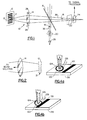
- Fig.3 there is illustrated a typical prior art device wherein LEDs 121, 121 illuminate a field of illumination 124 on target 123.
- a region of sensitivity 122 being smaller than field of illumination 124, is entirely included within field of illumination 124.
- the region of sensitivity 122 is viewed by light sensor 127 through optics 125, and presents a signal to amplifier 129 in response to detected light.
- Mark-sense detectors are typically employed in optical scanning devices, such as bar code scanners or readers, in which the output of the detector may be coupled to decoding circuitry.
- optical scanning devices such as bar code scanners or readers
- the output of the detector may be coupled to decoding circuitry.
- decoding circuitry There are a number of known optical effects that can produce errors in the determination of transitions between bars and spaces in a bar code symbol that is situated on a substrate, including the diffusion and laminate effects.
- the diffusion effect can be understood with reference to FIG. 4a and 4b. It results from light, shown representatively as beams 126, that is incident outside the region of sensitivity 122 of a light sensor. Beams 126 enter the substrate 138 on which a pattern is located, and are then scattered internally within the substrate into the region of sensitivity. A fraction of the scattered light is thus ultimately returned to the light sensor via region of sensitivity 122 where it contributes to the received signal level. In scanning applications such as bar code scanning there is another consequence of the diffusion effect. In this application the region of sensitivity travels across dark bars that are separated by fields of light spaces. These spaces are referred to herein as white spaces; however those skilled in the art will understand that areas of high reflectivity are denoted.
- the bar 139 will absorb more light than does a white space of similar dimension. Since some light 128 is absorbed, less is available to scatter into the approaching region of sensitivity. Thus the diffusion effect differs quantitatively when a bar is near the region of sensitivity than when it is not.
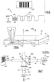
- FIG. 5 shows an analog waveform 130 generated by a bar code scanner utilizing flood illumination which has scanned bar code symbol 132. It will be apparent that the signal minima 137 corresponding to the wide dark bars are quite sharp, while the maxima 135 corresponding to the intervening white spaces are rounded.
- the peaks 136 corresponding to the narrow white spaces between the narrow dark bars 134 are reduced in amplitude relative to maxima 135 corresponding to wide white spaces 135 between the wide dark bars 137.
- This appearance is predicted by the above discussion of the diffusion effect. If the narrow dark bars could not be resolved due to the modulation transfer function of the reader's optical system, the patterns would have been symmetrical about the maxima and minima. While the diffusion effect has been explained in connection with a bar code scanner, it influences non-scanning readers of optical patterns as well. In summary, the diffusion effect tends to reduce the apparent white level in the vicinity of dark bars while not affecting the black level.
- the laminate effect is caused by the light that is scattered from outside the region of sensitivity being totally internally reflected at the overlaminate-to-air interface onto the region of sensitivity.
- FIG. 6 where the laminate effect is depicted diagrammatically. During the lamination process an adhesive flows over the bar code symbol substrate 140, expelling the air between laminate 141 and bar code symbol 142. As a result, the laminate 141 and bar code symbol 142 are in intimate contact and are essentially. index matched.
- the diffusion effect As in the case of the diffusion effect, as the region of sensitivity passes over the bar code symbol, some of the incident light will be absorbed by dark bars adjacent to the region of sensitivity, thereby reducing the white space signal level.
- the magnitude of the laminate effect is a function of laminate thickness, the dimensions of the bar code symbol, reflectance of the bars and spaces, nominal diffusion length in the substrate, and refractive index. While laminate effects are sometimes difficult to quantify, the range of this effect can be quite large.
- the laminate and diffusion effects are known to degrade the performance of bar code scanners, other types of mark-sense detectors, and image detecting apparatus generally.
- a laminated bar code symbol typically exhibits both the diffusion and the laminate effects.
- flood sensitivity an analogous argument can be made for the case where a small source of illumination is used in conjunction with a large region of sensitivity, so called flood sensitivity.
- a number of methods have been employed in the prior art that tend to bring the beams of light from the light source and those directed to the light sensor from the target into alignment, establishing a common operational region.
- the images of the light source and the defined region of sensitivity are generally not congruent throughout a relatively large depth of field. For this reason, all these systems are sensitive to the degrading effects of the diffusion and laminate effects over all or most of their operational depth of field.
- U.S. Pat. No. 4,675,531 to Clark et al shows a scanner that has coaxial incident and reflective beams, achieved by a multi-surfaced lens arrangement.
- the beams while having the same optical axis, could not define a light source image that is congruent to a region of sensitivity except in the focal plane. This device would not be suitable for applications requiring a larger depth of focus where flood illumination is undesirable.
- the optical assembly can be housed within a mark-sense detector, such as a bar code reader.
- a light source is aimed at a beam splitter that diverts a portion of the light beam through optics that focus the light on a reflective target containing a bar code symbol to be scanned.
- the reflected beam is returned through the optics and the beam splitter, and a portion of the reflected beam is conducted to a light sensor. In this manner, the light path from the detector to the optical sensor is split twice by the beam splitter.
- the optics are configured so that the light beams that define the field of illumination and the region of sensitivity and which pass between the optics and the target are congruent, having identical optical axes and angles of divergence.
- the field of illumination and region of sensitivity are brought into precise rotational alignment, such that the image of the light source is substantially coplanar and coextensive with the region of sensitivity in a working depth of field in which a target is located.
- the region of sensitivity is thus congruent with the field of illumination in any plane throughout the depth of field of the optics.
- Field stops may be provided for the light source and the light sensor in order to better define the dimensions of the field of view and field of illumination. When this is done an image of the light source field stop is projected precisely onto the region of sensitivity, and the back-projection of the region of sensitivity is focused on and coextensive with the field stop of the light sensor.
- assembly 10 is generally contained within the housing of a bar code scanner.
- the housing has a port to permit the passage of light therethrough in a desired direction.
- a function of the housing with respect to assembly 10 is the exclusion of unwanted light from light sensor 24.
- the invention may be practiced in other applications with any suitable means for the exclusion of unwanted light, such as a shield, or a partially enclosing canopy.
- Light source 26 emits a beam of light 36 that in the preferred embodiment has a sectional area and configuration that are defined by light source field stop 20.
- Light source 26 is preferably an LED or a laser, but could be an incandescent lamp, arc lamp, or any suitable source of light. If the image of light source field stop 20 as projected onto target 12 is noncircular, then the light source field stop 20 is suitably aligned about a rotational axis so that the field of illumination will be rotationally aligned with minimal bar code symbol element 13. Alternatively the optics can be configured to achieve rotational alignment. Light source field stop 20 is preferably circular; however other field stop designs may be employed.
- Light beam 36 eventually strikes beam splitter 15, a conventional partially silvered mirror type splitter that is disposed at a 45 degree angle to light beam 36. Other angles could be used to accommodate specific applications. Normally a 50% beam splitter is used, but this may be varied if desired. A proportion of beam 36 continues beyond beam splitter 15 and is lost; the remainder of the beam is reflected by beam splitter 15 and is directed to lens 14 at an angle of divergence 18.
- Lens 14 is any suitable lens or system of lenses that focuses an image of light source field stop 20 on bar code symbol 12, also shown in FIG. 2.
- Aperture 28 is provided to control lens aberrations.
- Region 21 defines the useful working depth of field of the instrument, and it may be varied by suitable design of the aperture - lens combination, as is well known in the art.
- the width dimension of the optical image of the light source field stop 20 formed thereon by lens 14 is of the order of the lateral dimension of the bar code symbol minimum element width 13.
- Reflected light from a region 17 is captured by lens 14 and returned to beam splitter 15. A portion of the light passes through the beam splitter, and an image of region 17 of the bar code symbol is projected by lens 14 onto light sensor field stop 22. Light energy reflected from region 17 is thus eventually received by light sensor 24, which generates a signal in response thereto.
- the signal produced by sensor 24 is coupled to conventional signal processing circuitry.
- the light beam 38 extending from light sensor 24 to beam splitter 15 as defined by light sensor field stop 22 has an angle of divergence 16 that is equal to angle 18.
- Field stops 20 and 22 should be equal in size and configuration. They are positioned equidistant from the beam splitter, close to the light source and light sensor respectively, and are oriented such that their optical images in region 21 are coaxial, coplanar and coextensive. The cones of light beams defined by the field stops will thus be congruent in three dimensions between the beam splitter 15 and the optical images of field stops 20 and 22 in region 21.
- the light sensor 24 is conventional and can be a photodiode, avalanche photodiode, photomultiplier, phototransistor, or a photo-FET.
- field stops 20 and 22 It is possible to operate the apparatus without field stops 20 and 22, and directly focus the images of optically sensitive areas of light sensor 24 and of light source 26 in region 21.
- the field stops are useful in avoiding interference from filament images and the structural detail of the light sensor.
- the field stops 20 and 22 may be implemented as an integral part of the light source 26 and the light sensor 24 respectively.
- the light sensor of course, is responsive to defocused light that has passed through light sensor field stop 22.
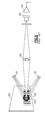
- FIG. 7 there is shown an alternative embodiment of the invention, in which reference numerals of similar elements in respect of FIG. 1 are advanced by 400.
- Light source 426 emits a beam of light 436, preferably through a light source field stop 420 that defines its sectional area and configuration.
- Light beam 436 is now directed through a first lens 514 at an angle of divergence 418. Lens aberrations are reduced by aperture 528, associated with the lens 514.
- the light beam having passed through lens 514, eventually strikes beam splitter 415, which is disposed at a 45 degree angle to the optical axis of incident light beam 436. Other angles could be used to accommodate specific applications. Normally a 50% beam splitter is used, but this may be varied if desired.
- a portion of beam 436 continues beyond beam splitter 415 and is lost; the remainder of the beam is reflected by beam splitter 415 and is directed to target 412, converging at an angle 419.
- the width dimension of the optical image of the light source field stop 420 formed thereon by lens 514 is of the order of the lateral dimension of the bar code symbol minimum element width 413.
- Reflected light from the region 417 of the bar code symbol is incident on beam splitter 415.
- a portion of the light passes through the beam splitter, through a second lens 414, onto light sensor field stop 422, and is eventually received by light sensor 424, which generates a signal in response thereto.
- This signal is conducted to signal processing circuitry.
- Aperture 428, associated with lens 414, reduces lens aberrations.
- lens - aperture combinations 414, 428 and 514, 528 are designed so that the images of field stops 420 and 422 are substantially coaxial, coplanar, and coextensive in a working depth of field in which bar code symbol 412 is located.
- the lenses are not necessarily identical, but may be designed to accommodate geometrical constraints in the housing of a scanner that require the light paths between light source 426 and beam splitter 415 to be of different length from the path between beam splitter 415 and light sensor 424.
- Field stops 420 and 422 should be geometrically similar in shape, but need not be equal in size. They are positioned close to the light source and light sensor respectively. The cones of light beams defined by the field stops will be substantially congruent in three dimensions in the working depth of the instrument.
- Field stops 422 and 420 may be integrated into the light sensor 424 and the light source 426. It will be appreciated that the positions of light source 426 and light sensor 424 can be interchanged without affecting the function of the apparatus. Folded light paths may also be employed so long as the desired congruence of the light beams in the working region as discussed above is maintained.
Landscapes
- Physics & Mathematics (AREA)
- Electromagnetism (AREA)
- Engineering & Computer Science (AREA)
- Health & Medical Sciences (AREA)
- General Health & Medical Sciences (AREA)
- Toxicology (AREA)
- Artificial Intelligence (AREA)
- Computer Vision & Pattern Recognition (AREA)
- General Physics & Mathematics (AREA)
- Theoretical Computer Science (AREA)
- Image Input (AREA)
- Facsimile Scanning Arrangements (AREA)
Claims (14)
- Optische Anordnung zur Verwendung bei der Ermittlung von Zeichen, welche folgendes umfaßt:dadurch gekennzeichnet, daß sie außerdem folgendes umfaßt:ein Lichtquellenmittel (26, 426) zum Aussenden eines ersten Lichtstrahls (36, 436), der in ein Ausleuchtungsfeld eines Ziels (12, 412) einfällt, wobei das genannte Ziel sich in einer Arbeits-Schärfentiefe (21) befindet;ein Lichtsensormittel (24, 424) zum Erzeugen eines Signals in Abhängigkeit von in dem genannten ersten Strahl zu dem genannten Ziel befördertem und von einem dort befindlichen Empfindlichkeitsbereich zurückkehrendem Licht, wobei das genannte zurückkehrende Licht in einem zweiten Lichtstrahl (38, 438) befördert wird, der von dem genannten Ziel zu dem genannten Lichtsensormittel verläuft;optische Mittel (14, 414), welche in dem genannten ersten Lichtstrahl und in dem genannten zweiten Lichtstrahl angeordnet sind, um ein Abbild des genannten Lichtquellenmittels auf dem genannten Ziel zu bilden;Mittel (20, 420) zum Ausrichten des genannten Lichtquellenmittels auf eine Lichtweite und eine Form auf dem genannten Ziel, welche mit einer Lichtweite und Form des genannten Abbildes des genannten Lichtsensormittels auf dem genannten Ziel identisch sind,und dadurch, daß:Mittel (22, 422) zum Dimensionieren des genannten ersten Strahls und/oder des genannten zweiten Strahls, so daß der genannte erste Strahl und der genannte zweite Strahl zwischen dem genannten Ziel und den genannten optischen Mitteln genau übereinanderliegen;und Mittel zum Fernhalten unerwünschten Lichtes von dem genannten Lichtsensormittel;die genannten optischen Mittel (14, 414) eine Rückprojektion von dem genannten Empfindlichkeitsbereich auf dem genannten Lichtsensormittel (24, 424) bilden, wobei die genannte Rückprojektion in dem genannten zweiten Strahl übertragen wird und wobei der genannte erste Strahl und der genannte zweite Strahl einen gemeinsamen Weg zwischen den genannten optischen Mitteln und dem genannten Ziel zurücklegen;und das genannte Ausleuchtungsfeld auf jeder beliebigen Ebene in der gesamten genannten Arbeits-Schärfentiefe genau mit dem genannten Empfindlichkeitsbereich zusammenfällt.
- Anordnung nach Anspruch 1, dadurch gekennzeichnet, daß das Mittel zum Ausrichten folgendes umfaßt:ein erstes Sehfeldblendenmittel (20, 420) in der Nähe des genannten Lichtquellenmittels;und ein zweites Sehfeldblendenmittel (22, 422) in der Nähe des genannten Lichtsensormittels.
- Anordnung nach Anspruch 1, dadurch gekennzeichnet, daß das genannte optische Mittel folgendes umfaßt:Strahlenteiler (15, 415), um einen Teil des genannten zurückkehrenden Lichtes auf das genannte Lichtsensormittel zu richten und um einen Teil des von dem genannten Lichtquellenmittel ausgesendeten Lichtes auf das genannte Ziel zu richten; undein Linsenmittel (14).
- Anordnung nach Anspruch 3, dadurch gekennzeichnet, daß das genannte Linsenmittel folgendes umfaßt:eine erste, zwischen dem genannten Strahlenteiler (415) und dem genannten Lichtquellenmittel (426) angeordnete Linse (514); undeine zweite, zwischen dem genannten Strahlenteiler (415) und dem genannten Lichtsensormittel (424) angeordnete Linse (414).
- Anordnung nach Anspruch 3, dadurch gekennzeichnet, daß das genannte Linsenmittel eine einzige, zwischen dem genannten Strahlenteiler (15) und dem genannten Ziel (12) angeordnete Linse (14) umfaßt.
- Anordnung nach Anspruch 1, dadurch gekennzeichnet, daß das genannte Mittel zum Ausrichten aus dem in das genannte Lichtquellenmittel (26, 426) integrierten ersten Sehfeldblendenmittel (20, 420) besteht.
- Anordnung nach Anspruch 1, dadurch gekennzeichnet, daß das genannte Mittel zum Dimensionieren aus dem in das genannte Lichtsensormittel (24, 424) integrierten zweiten Sehfeldblendenmittel (22, 422) besteht.
- Anordnung nach Anspruch 1, dadurch gekennzeichnet, daß die genannten Mittel zum Ausrichten und Dimensionieren aus dem ersten (20, 420) und dem zweiten (22, 422) Sehfeldblendenmittel bestehen, welche kreisförmige Sehfeldblenden umfassen.
- Anordnung nach Anspruch 1, dadurch gekennzeichnet, daß die genannten Mittel zum Ausrichten und Dimensionieren aus dem ersten (20, 420) und dem zweiten (22, 422) Sehfeldblendenmittel bestehen, welche elliptische Sehfeldblenden umfassen.
- Anordnung nach Anspruch 1, dadurch gekennzeichnet, daß die genannten Mittel zum Ausrichten und Dimensionieren aus dem ersten (20, 420) und dem zweiten (22, 422) Sehfeldblendenmittel bestehen, welche vieleckige Sehfeldblenden umfassen.
- Anordnung nach Anspruch 1, dadurch gekennzeichnet, daß die genannten Mittel zum Ausrichten und Dimensionieren aus dem ersten (20, 420) und dem zweiten (22, 422) Sehfeldblendenmittel bestehen, welche rechteckige Sehfeldblenden umfassen.
- Anordnung nach Anspruch 1, dadurch gekennzeichnet, daß das genannte Mittel (22, 422) zum Dimensionieren eine Objektivöffnung umfaßt.
- Anordnung nach Anspruch 1, dadurch gekennzeichnet, daß das genannte Lichtsensormittel aus der aus Photodiode, Lawinen-Photodiode, Photovervielfacher, Phototransistor und Photo-FET bestehenden Gruppe ausgewählt ist.
- Anordnung nach Anspruch 1, dadurch gekennzeichnet, daß das genannte Lichtquellenmittel aus der aus LED-Diode, Laser, Glühlampe und Bogenlampe bestehenden Gruppe ausgewählt ist.
Applications Claiming Priority (3)
| Application Number | Priority Date | Filing Date | Title |
|---|---|---|---|
| US82248492A | 1992-01-17 | 1992-01-17 | |
| US822484 | 1992-01-17 | ||
| PCT/US1993/000283 WO1993014471A1 (en) | 1992-01-17 | 1993-01-13 | Intimate source and detector and apparatus employing same |
Publications (2)
| Publication Number | Publication Date |
|---|---|
| EP0576662A1 EP0576662A1 (de) | 1994-01-05 |
| EP0576662B1 true EP0576662B1 (de) | 1998-06-17 |
Family
ID=25236156
Family Applications (1)
| Application Number | Title | Priority Date | Filing Date |
|---|---|---|---|
| EP93903449A Expired - Lifetime EP0576662B1 (de) | 1992-01-17 | 1993-01-13 | Gemeinsame quelle und detektor und davon gebrauch machende vorrichtung |
Country Status (5)
| Country | Link |
|---|---|
| US (1) | US5430286A (de) |
| EP (1) | EP0576662B1 (de) |
| JP (1) | JPH06506788A (de) |
| DE (1) | DE69319185D1 (de) |
| WO (1) | WO1993014471A1 (de) |
Families Citing this family (42)
| Publication number | Priority date | Publication date | Assignee | Title |
|---|---|---|---|---|
| US6631842B1 (en) | 2000-06-07 | 2003-10-14 | Metrologic Instruments, Inc. | Method of and system for producing images of objects using planar laser illumination beams and image detection arrays |
| US7387253B1 (en) | 1996-09-03 | 2008-06-17 | Hand Held Products, Inc. | Optical reader system comprising local host processor and optical reader |
| US5560291A (en) * | 1995-09-20 | 1996-10-01 | Shu; Ming Fang | Stamping machine |
| US6629641B2 (en) | 2000-06-07 | 2003-10-07 | Metrologic Instruments, Inc. | Method of and system for producing images of objects using planar laser illumination beams and image detection arrays |
| US5859418A (en) * | 1996-01-25 | 1999-01-12 | Symbol Technologies, Inc. | CCD-based bar code scanner with optical funnel |
| US7304670B1 (en) * | 1997-03-28 | 2007-12-04 | Hand Held Products, Inc. | Method and apparatus for compensating for fixed pattern noise in an imaging system |
| US6435411B1 (en) | 1997-04-21 | 2002-08-20 | Intermec Ip Corp. | Optoelectronic device for acquisition of images, in particular of bar codes |
| US7028899B2 (en) | 1999-06-07 | 2006-04-18 | Metrologic Instruments, Inc. | Method of speckle-noise pattern reduction and apparatus therefore based on reducing the temporal-coherence of the planar laser illumination beam before it illuminates the target object by applying temporal phase modulation techniques during the transmission of the plib towards the target |
| US7584893B2 (en) | 1998-03-24 | 2009-09-08 | Metrologic Instruments, Inc. | Tunnel-type digital imaging system for use within retail shopping environments such as supermarkets |
| US6269169B1 (en) * | 1998-07-17 | 2001-07-31 | Imaging Automation, Inc. | Secure document reader and method therefor |
| US6366707B1 (en) * | 1999-04-13 | 2002-04-02 | Hewlett-Packard Company | Imaging apparatus alignment system and method |
| US6959870B2 (en) | 1999-06-07 | 2005-11-01 | Metrologic Instruments, Inc. | Planar LED-based illumination array (PLIA) chips |
| US7270274B2 (en) | 1999-10-04 | 2007-09-18 | Hand Held Products, Inc. | Imaging module comprising support post for optical reader |
| US6912076B2 (en) * | 2000-03-17 | 2005-06-28 | Accu-Sort Systems, Inc. | Coplanar camera scanning system |
| US7607581B2 (en) | 2003-11-13 | 2009-10-27 | Metrologic Instruments, Inc. | Digital imaging-based code symbol reading system permitting modification of system features and functionalities |
| US7708205B2 (en) | 2003-11-13 | 2010-05-04 | Metrologic Instruments, Inc. | Digital image capture and processing system employing multi-layer software-based system architecture permitting modification and/or extension of system features and functions by way of third party code plug-ins |
| US7954719B2 (en) | 2000-11-24 | 2011-06-07 | Metrologic Instruments, Inc. | Tunnel-type digital imaging-based self-checkout system for use in retail point-of-sale environments |
| US7540424B2 (en) | 2000-11-24 | 2009-06-02 | Metrologic Instruments, Inc. | Compact bar code symbol reading system employing a complex of coplanar illumination and imaging stations for omni-directional imaging of objects within a 3D imaging volume |
| US7464877B2 (en) | 2003-11-13 | 2008-12-16 | Metrologic Instruments, Inc. | Digital imaging-based bar code symbol reading system employing image cropping pattern generator and automatic cropped image processor |
| US8042740B2 (en) | 2000-11-24 | 2011-10-25 | Metrologic Instruments, Inc. | Method of reading bar code symbols on objects at a point-of-sale station by passing said objects through a complex of stationary coplanar illumination and imaging planes projected into a 3D imaging volume |
| US7594609B2 (en) | 2003-11-13 | 2009-09-29 | Metrologic Instruments, Inc. | Automatic digital video image capture and processing system supporting image-processing based code symbol reading during a pass-through mode of system operation at a retail point of sale (POS) station |
| US7128266B2 (en) | 2003-11-13 | 2006-10-31 | Metrologic Instruments. Inc. | Hand-supportable digital imaging-based bar code symbol reader supporting narrow-area and wide-area modes of illumination and image capture |
| US7490774B2 (en) | 2003-11-13 | 2009-02-17 | Metrologic Instruments, Inc. | Hand-supportable imaging based bar code symbol reader employing automatic light exposure measurement and illumination control subsystem integrated therein |
| WO2002063543A2 (en) | 2001-01-22 | 2002-08-15 | Hand Held Products, Inc. | Optical reader having partial frame operating mode |
| US7268924B2 (en) * | 2001-01-22 | 2007-09-11 | Hand Held Products, Inc. | Optical reader having reduced parameter determination delay |
| US7270273B2 (en) | 2001-01-22 | 2007-09-18 | Hand Held Products, Inc. | Optical reader having partial frame operating mode |
| US7331523B2 (en) | 2001-07-13 | 2008-02-19 | Hand Held Products, Inc. | Adaptive optical image reader |
| US7513428B2 (en) | 2001-11-21 | 2009-04-07 | Metrologic Instruments, Inc. | Planar laser illumination and imaging device employing laser current modulation to generate spectral components and reduce temporal coherence of laser beam, so as to achieve a reduction in speckle-pattern noise during time-averaged detection of images of objects illuminated thereby during imaging operations |
| US7055747B2 (en) | 2002-06-11 | 2006-06-06 | Hand Held Products, Inc. | Long range optical reader |
| US7219843B2 (en) * | 2002-06-04 | 2007-05-22 | Hand Held Products, Inc. | Optical reader having a plurality of imaging modules |
| US7090132B2 (en) * | 2002-06-11 | 2006-08-15 | Hand Held Products, Inc. | Long range optical reader |
| US8596542B2 (en) | 2002-06-04 | 2013-12-03 | Hand Held Products, Inc. | Apparatus operative for capture of image data |
| US20030222147A1 (en) | 2002-06-04 | 2003-12-04 | Hand Held Products, Inc. | Optical reader having a plurality of imaging modules |
| US7841533B2 (en) | 2003-11-13 | 2010-11-30 | Metrologic Instruments, Inc. | Method of capturing and processing digital images of an object within the field of view (FOV) of a hand-supportable digitial image capture and processing system |
| US7017812B1 (en) * | 2003-11-26 | 2006-03-28 | The United States Of America As Represented By The Administrator Of The National Aeronautics And Space Administration | Variable distance angular symbology reader |
| US7852519B2 (en) | 2007-02-05 | 2010-12-14 | Hand Held Products, Inc. | Dual-tasking decoder for improved symbol reading |
| US8628015B2 (en) | 2008-10-31 | 2014-01-14 | Hand Held Products, Inc. | Indicia reading terminal including frame quality evaluation processing |
| US8587595B2 (en) | 2009-10-01 | 2013-11-19 | Hand Held Products, Inc. | Low power multi-core decoder system and method |
| CN102870121B (zh) | 2010-03-11 | 2015-04-29 | 得利捷Ip科技有限公司 | 图像捕捉装置 |
| US8561903B2 (en) | 2011-01-31 | 2013-10-22 | Hand Held Products, Inc. | System operative to adaptively select an image sensor for decodable indicia reading |
| US8608071B2 (en) | 2011-10-17 | 2013-12-17 | Honeywell Scanning And Mobility | Optical indicia reading terminal with two image sensors |
| MX336455B (es) * | 2011-11-15 | 2016-01-20 | Nestec Sa | Soporte y capsula para preparar una bebida por centrifugacion, sistema y metodo para preparar una bebida por centrifugacion. |
Family Cites Families (13)
| Publication number | Priority date | Publication date | Assignee | Title |
|---|---|---|---|---|
| US3744026A (en) * | 1970-06-10 | 1973-07-03 | Identicon Corp | Optical label scanning |
| NL181693C (nl) * | 1974-11-29 | 1987-10-01 | Philips Nv | Inrichting voor het langs optische weg uitlezen van een stralingsreflekterende registratiedrager. |
| US4143809A (en) * | 1977-10-11 | 1979-03-13 | Hewlett-Packard Company | Optical bar code reader |
| US4201910A (en) * | 1978-03-27 | 1980-05-06 | Innovation Industries, Inc. | Photosensor assembly |
| JPS54147035A (en) * | 1978-05-10 | 1979-11-16 | Minolta Camera Co Ltd | Tessar type photographic lens placed behind aperture |
| FR2479511A1 (fr) * | 1980-03-25 | 1981-10-02 | Rao | Perfectionnements aux lecteurs de code electro-optiques |
| US4346292A (en) * | 1981-02-02 | 1982-08-24 | International Business Machines Corporation | Coaxial optical scanner |
| JPS57152074A (en) * | 1981-03-16 | 1982-09-20 | Nippon Denso Co Ltd | Bar code reader |
| DE3242219C1 (de) * | 1982-11-15 | 1984-02-16 | Erwin Sick Gmbh Optik-Elektronik, 7808 Waldkirch | Optisches Markenerkennungsgeraet |
| US4675531A (en) * | 1985-03-28 | 1987-06-23 | Polaroid Corporation | Optical scanner having a multi-surfaced lens arrangement for producing a rotationally symmetric beam |
| JP2608893B2 (ja) * | 1987-07-10 | 1997-05-14 | 松下電器産業株式会社 | 光学的パターン検出装置 |
| US4816659A (en) * | 1987-10-13 | 1989-03-28 | Control Module Inc. | Bar code reader head |
| EP0524349A1 (de) * | 1991-07-08 | 1993-01-27 | Opticon Sensors Europe B.V. | Abtaster mit zwei Brennweiten und die Verwendung eines solchen Abtasters als Lesestift für Kodierungen |
-
1993
- 1993-01-13 EP EP93903449A patent/EP0576662B1/de not_active Expired - Lifetime
- 1993-01-13 JP JP5512637A patent/JPH06506788A/ja active Pending
- 1993-01-13 DE DE69319185T patent/DE69319185D1/de not_active Expired - Lifetime
- 1993-01-13 WO PCT/US1993/000283 patent/WO1993014471A1/en not_active Ceased
-
1994
- 1994-02-25 US US08/202,669 patent/US5430286A/en not_active Expired - Lifetime
Also Published As
| Publication number | Publication date |
|---|---|
| WO1993014471A1 (en) | 1993-07-22 |
| US5430286A (en) | 1995-07-04 |
| EP0576662A1 (de) | 1994-01-05 |
| JPH06506788A (ja) | 1994-07-28 |
| DE69319185D1 (de) | 1998-07-23 |
Similar Documents
| Publication | Publication Date | Title |
|---|---|---|
| EP0576662B1 (de) | Gemeinsame quelle und detektor und davon gebrauch machende vorrichtung | |
| EP0610504B1 (de) | Informations-lesegerät | |
| US5319182A (en) | Integrated solid state light emitting and detecting array and apparatus employing said array | |
| US4682016A (en) | Pen-type bar code reader | |
| JP2772521B2 (ja) | 投光反射型光検出器の光学系 | |
| US4753498A (en) | Optical reader | |
| US11852852B2 (en) | Patterned mirror edge for stray beam and interference mitigation | |
| KR100374244B1 (ko) | 광디바이스 | |
| US7732752B2 (en) | Continuous base beneath optical sensor and optical homodyning system | |
| US11886649B2 (en) | Optical navigation device | |
| US20030127520A1 (en) | Optical data code reader | |
| JP2002251259A (ja) | タッチパネル装置 | |
| US20020104888A1 (en) | Systems and methods for an encoded information reader | |
| KR920008507B1 (ko) | 광학적패턴 검출장치 | |
| JPH0526725A (ja) | 限定反射形センサ | |
| JP3180019B2 (ja) | 原稿エッジ検出装置 | |
| JP2776715B2 (ja) | 光学読取装置 | |
| JP3578602B2 (ja) | 原稿検知装置 | |
| RU2179304C2 (ru) | Фоторегистратор движущейся метки | |
| JPH0668755A (ja) | 光センサ | |
| KR200190808Y1 (ko) | 광엔코더 | |
| JPH01227001A (ja) | 位置検出装置 | |
| JPH06843Y2 (ja) | 反射型光センサ | |
| JPH0469528A (ja) | 領域限定反射型光電センサ | |
| JPS6247016A (ja) | 焦点距離検出方法 |
Legal Events
| Date | Code | Title | Description |
|---|---|---|---|
| PUAI | Public reference made under article 153(3) epc to a published international application that has entered the european phase |
Free format text: ORIGINAL CODE: 0009012 |
|
| AK | Designated contracting states |
Kind code of ref document: A1 Designated state(s): BE DE FR GB IT LU NL |
|
| 17P | Request for examination filed |
Effective date: 19940105 |
|
| 17Q | First examination report despatched |
Effective date: 19960627 |
|
| GRAG | Despatch of communication of intention to grant |
Free format text: ORIGINAL CODE: EPIDOS AGRA |
|
| GRAG | Despatch of communication of intention to grant |
Free format text: ORIGINAL CODE: EPIDOS AGRA |
|
| GRAH | Despatch of communication of intention to grant a patent |
Free format text: ORIGINAL CODE: EPIDOS IGRA |
|
| GRAH | Despatch of communication of intention to grant a patent |
Free format text: ORIGINAL CODE: EPIDOS IGRA |
|
| GRAH | Despatch of communication of intention to grant a patent |
Free format text: ORIGINAL CODE: EPIDOS IGRA |
|
| GRAH | Despatch of communication of intention to grant a patent |
Free format text: ORIGINAL CODE: EPIDOS IGRA |
|
| GRAA | (expected) grant |
Free format text: ORIGINAL CODE: 0009210 |
|
| AK | Designated contracting states |
Kind code of ref document: B1 Designated state(s): BE DE FR GB IT LU NL |
|
| PG25 | Lapsed in a contracting state [announced via postgrant information from national office to epo] |
Ref country code: NL Free format text: LAPSE BECAUSE OF FAILURE TO SUBMIT A TRANSLATION OF THE DESCRIPTION OR TO PAY THE FEE WITHIN THE PRESCRIBED TIME-LIMIT Effective date: 19980617 Ref country code: IT Free format text: LAPSE BECAUSE OF FAILURE TO SUBMIT A TRANSLATION OF THE DESCRIPTION OR TO PAY THE FEE WITHIN THE PRE;WARNING: LAPSES OF ITALIAN PATENTS WITH EFFECTIVE DATE BEFORE 2007 MAY HAVE OCCURRED AT ANY TIME BEFORE 2007. THE CORRECT EFFECTIVE DATE MAY BE DIFFERENT FROM THE ONE RECORDED.SCRIBED TIME-LIMIT Effective date: 19980617 Ref country code: BE Free format text: LAPSE BECAUSE OF FAILURE TO SUBMIT A TRANSLATION OF THE DESCRIPTION OR TO PAY THE FEE WITHIN THE PRESCRIBED TIME-LIMIT Effective date: 19980617 |
|
| ET | Fr: translation filed | ||
| REF | Corresponds to: |
Ref document number: 69319185 Country of ref document: DE Date of ref document: 19980723 |
|
| PG25 | Lapsed in a contracting state [announced via postgrant information from national office to epo] |
Ref country code: DE Free format text: LAPSE BECAUSE OF FAILURE TO SUBMIT A TRANSLATION OF THE DESCRIPTION OR TO PAY THE FEE WITHIN THE PRESCRIBED TIME-LIMIT Effective date: 19980918 |
|
| NLV1 | Nl: lapsed or annulled due to failure to fulfill the requirements of art. 29p and 29m of the patents act | ||
| PG25 | Lapsed in a contracting state [announced via postgrant information from national office to epo] |
Ref country code: LU Free format text: LAPSE BECAUSE OF NON-PAYMENT OF DUE FEES Effective date: 19990113 Ref country code: GB Free format text: LAPSE BECAUSE OF NON-PAYMENT OF DUE FEES Effective date: 19990113 |
|
| K2C3 | Correction of patent specification (complete document) published |
Effective date: 19980617 |
|
| PLBE | No opposition filed within time limit |
Free format text: ORIGINAL CODE: 0009261 |
|
| STAA | Information on the status of an ep patent application or granted ep patent |
Free format text: STATUS: NO OPPOSITION FILED WITHIN TIME LIMIT |
|
| 26N | No opposition filed | ||
| GBPC | Gb: european patent ceased through non-payment of renewal fee |
Effective date: 19990113 |
|
| PG25 | Lapsed in a contracting state [announced via postgrant information from national office to epo] |
Ref country code: FR Free format text: LAPSE BECAUSE OF NON-PAYMENT OF DUE FEES Effective date: 19990930 |
|
| REG | Reference to a national code |
Ref country code: FR Ref legal event code: ST |