EP0576663B1 - Harmonisation symetrique de modes de resonateur - Google Patents
Harmonisation symetrique de modes de resonateur Download PDFInfo
- Publication number
- EP0576663B1 EP0576663B1 EP93903681A EP93903681A EP0576663B1 EP 0576663 B1 EP0576663 B1 EP 0576663B1 EP 93903681 A EP93903681 A EP 93903681A EP 93903681 A EP93903681 A EP 93903681A EP 0576663 B1 EP0576663 B1 EP 0576663B1
- Authority
- EP
- European Patent Office
- Prior art keywords
- optical fiber
- input
- output
- electromagnetic waves
- resonator
- Prior art date
- Legal status (The legal status is an assumption and is not a legal conclusion. Google has not performed a legal analysis and makes no representation as to the accuracy of the status listed.)
- Expired - Lifetime
Links
- 239000013307 optical fiber Substances 0.000 claims abstract description 110
- 230000008878 coupling Effects 0.000 claims abstract description 76
- 238000010168 coupling process Methods 0.000 claims abstract description 76
- 238000005859 coupling reaction Methods 0.000 claims abstract description 76
- 230000010287 polarization Effects 0.000 claims abstract description 55
- 230000001902 propagating effect Effects 0.000 claims abstract description 25
- 239000003638 chemical reducing agent Substances 0.000 claims abstract description 4
- 230000003287 optical effect Effects 0.000 claims description 56
- 230000004044 response Effects 0.000 claims description 10
- 230000005670 electromagnetic radiation Effects 0.000 claims description 7
- 238000012546 transfer Methods 0.000 claims description 4
- 230000010354 integration Effects 0.000 claims description 3
- 238000012544 monitoring process Methods 0.000 claims 2
- 239000000835 fiber Substances 0.000 description 61
- 239000011159 matrix material Substances 0.000 description 43
- 230000000694 effects Effects 0.000 description 32
- 230000005684 electric field Effects 0.000 description 19
- 230000008859 change Effects 0.000 description 18
- 239000013598 vector Substances 0.000 description 17
- 238000012545 processing Methods 0.000 description 9
- 230000010363 phase shift Effects 0.000 description 8
- 230000006870 function Effects 0.000 description 7
- 238000004458 analytical method Methods 0.000 description 6
- 230000005540 biological transmission Effects 0.000 description 5
- 239000000463 material Substances 0.000 description 5
- 230000008901 benefit Effects 0.000 description 4
- 238000010586 diagram Methods 0.000 description 3
- 230000005672 electromagnetic field Effects 0.000 description 3
- 230000010355 oscillation Effects 0.000 description 3
- 230000003252 repetitive effect Effects 0.000 description 3
- 238000000926 separation method Methods 0.000 description 3
- 239000007787 solid Substances 0.000 description 3
- 230000003595 spectral effect Effects 0.000 description 3
- 238000001228 spectrum Methods 0.000 description 3
- 239000000470 constituent Substances 0.000 description 2
- 230000001808 coupling effect Effects 0.000 description 2
- 230000001934 delay Effects 0.000 description 2
- 230000014509 gene expression Effects 0.000 description 2
- 230000006872 improvement Effects 0.000 description 2
- 238000003780 insertion Methods 0.000 description 2
- 230000037431 insertion Effects 0.000 description 2
- GQYHUHYESMUTHG-UHFFFAOYSA-N lithium niobate Chemical compound [Li+].[O-][Nb](=O)=O GQYHUHYESMUTHG-UHFFFAOYSA-N 0.000 description 2
- 229910052751 metal Inorganic materials 0.000 description 2
- 239000002184 metal Substances 0.000 description 2
- 238000004806 packaging method and process Methods 0.000 description 2
- 238000006467 substitution reaction Methods 0.000 description 2
- 230000007704 transition Effects 0.000 description 2
- 238000012935 Averaging Methods 0.000 description 1
- 238000009825 accumulation Methods 0.000 description 1
- 230000002411 adverse Effects 0.000 description 1
- 230000003321 amplification Effects 0.000 description 1
- 238000012512 characterization method Methods 0.000 description 1
- 238000006880 cross-coupling reaction Methods 0.000 description 1
- 230000001186 cumulative effect Effects 0.000 description 1
- 230000008030 elimination Effects 0.000 description 1
- 238000003379 elimination reaction Methods 0.000 description 1
- 230000007613 environmental effect Effects 0.000 description 1
- 230000005284 excitation Effects 0.000 description 1
- 230000000977 initiatory effect Effects 0.000 description 1
- 230000002452 interceptive effect Effects 0.000 description 1
- 238000002955 isolation Methods 0.000 description 1
- 238000012423 maintenance Methods 0.000 description 1
- 238000005259 measurement Methods 0.000 description 1
- 238000000034 method Methods 0.000 description 1
- 238000003199 nucleic acid amplification method Methods 0.000 description 1
- 230000000737 periodic effect Effects 0.000 description 1
- 230000008569 process Effects 0.000 description 1
- 230000000644 propagated effect Effects 0.000 description 1
- 238000005086 pumping Methods 0.000 description 1
- 230000009467 reduction Effects 0.000 description 1
- 239000004065 semiconductor Substances 0.000 description 1
- 230000035939 shock Effects 0.000 description 1
- 230000009466 transformation Effects 0.000 description 1
- 230000001052 transient effect Effects 0.000 description 1
Images


Classifications
-
- G—PHYSICS
- G01—MEASURING; TESTING
- G01C—MEASURING DISTANCES, LEVELS OR BEARINGS; SURVEYING; NAVIGATION; GYROSCOPIC INSTRUMENTS; PHOTOGRAMMETRY OR VIDEOGRAMMETRY
- G01C19/00—Gyroscopes; Turn-sensitive devices using vibrating masses; Turn-sensitive devices without moving masses; Measuring angular rate using gyroscopic effects
- G01C19/58—Turn-sensitive devices without moving masses
- G01C19/64—Gyrometers using the Sagnac effect, i.e. rotation-induced shifts between counter-rotating electromagnetic beams
- G01C19/72—Gyrometers using the Sagnac effect, i.e. rotation-induced shifts between counter-rotating electromagnetic beams with counter-rotating light beams in a passive ring, e.g. fibre laser gyrometers
- G01C19/727—Gyrometers using the Sagnac effect, i.e. rotation-induced shifts between counter-rotating electromagnetic beams with counter-rotating light beams in a passive ring, e.g. fibre laser gyrometers using a passive ring resonator
Definitions
- the present invention relates to fiber optic gyroscopes used for rotation sensing and, more particularly, to resonator fiber optic gyroscopes.
- Fiber optic gyroscopes are an attractive means with which to sense rotation. They can be made quite small and still be constructed to withstand considerable mechanical shock, temperature change, and other environmental extremes. In the absence of moving parts, they can be nearly maintenance free, and they have the potential to become economical in cost. They can also be sensitive to low rotation rates that can be a problem in other kinds of optical gyroscopes.
- optical inertial rotation sensors which use the well known Sagnac effect to detect rotation about a pertinent axis thereof.
- active optical gyroscopes having the gain medium contained in an optical cavity therein, such as the ring laser gyroscope, and passive optical gyroscopes without any gain medium in the primary optical path, such as the interferometric fiber optic gyroscope and the ring resonator fiber optic gyroscope.
- the avoidance of having the active medium along the primary optical path in the gyroscope eliminates some problems which are encountered in active gyroscopes such as low rotation rate lock-in, bias drift and some causes of scale factor variation.
- Interferometric fiber optic gyroscopes typically employ a single spatial mode optical fiber of a substantial length formed into a coil, this substantial length of optical fiber being relatively costly.
- Resonator fiber optic gyroscopes are constructed with relatively few turns of a single spatial mode optical fiber giving them the potential of being more economical than interferometric fiber optic gyroscopes.
- a resonator fiber optic gyroscope typically has three to fifty meters of optical fiber in its coil versus 100 to 2,000 meters of optical fiber in coils used in interferometric fiber optic gyroscopes.
- resonator fiber optic gyroscopes appear to have certain advantages in scale factor linearity and dynamic range.
- these coils are part of a substantially closed optical path in which an electromagnetic wave, or light wave, is introduced and split into a pair of such waves, to propagate in opposite directions through the optical fiber coil to both ultimately impinge on a photodetector or photodetectors, a single photodetector for both waves in interferometric fiber optic gyroscopes and on corresponding ones of a pair of photodetectors in resonator fiber optic gyroscopes.
- Rotation about the sensing axis of the core of the coiled optical fiber in either direction provides an effective optical path length increase in one rotational direction and an effective optical path length decrease in the opposite rotational direction for one member of this pair of electromagnetic waves.
- one or more optical frequency shifters are used to each effectively adjust the frequency of a corresponding one of the pair of electromagnetic waves that circulate in opposite directions in the resonator fiber optic coil. This is accomplished through such a frequency shifter shifting the frequency of a corresponding input electromagnetic wave giving rise to the resonator electromagnetic wave of interest.
- the frequencies of each member of the pair of electromagnetic waves can be kept in resonance with the effective optical path length that wave is experiencing in the resonator fiber optic coil. Hence, any frequency difference between these waves becomes a measure of the rotation rate experienced by the resonator fiber optic coil about the axis around which this coil has been positioned.
- each wave has the portions thereof that previously were introduced in the resonator coil and have not yet dissipated, and the portions thereof currently being introduced in the resonator coii, at a frequency such that they are all in phase with one another so they additively combine to provide a peak in the intensity of that wave in that resonator over a local range of frequencies.
- the difference in frequency between the members of the pair of opposing electromagnetic waves in a resonant fiber optic gyroscope is desired to be constant when rotation conditions about the resonator optic fiber coil axis are unchanging thereby requiring that stable resonance conditions occur in that resonator in those circumstances.
- phase modulator Because of the impossibility of having a phase modulator provide an infinite duration linear ramp with respect to time, a repetitive linear ramp with periodic resetting of the phase to a reference value must be used.
- the resulting sawtooth phase change waveform results in what is termed serrodyne phase modulation of those electromagnetic waves passing through the modulator.
- Resonator 10 is formed of a single spatial mode optical fiber which has two polarization eigenstates. Avoiding different optical path lengths for electromagnetic waves in each state is initially solved by thoroughly mixing the polarized waves in each such state. Such mixing is achieved by fabricating the resonator coil with two ends of a three to fifty meter length of such fiber spliced together so that the birefringence principal axes of the fiber are rotated 90° with respect to each other on opposite sides of a splice, 13.
- the resonator fiber is characterized by a loss coefficient, a, and, for such a splice, an average of the propagation constants with the principle birefringent axes as will be more fully described below.
- Directional coupler 11 is fabricated by appropriately fusing together an input optical fiber, 14, with the optical fiber in resonator 10, the fibers being tapered as they come into the fused portion on either side of that portion.
- Directional coupler 11 provides a phase shift of rc/2 between an input electromagnetic wave and the resulting electromagnetic wave at the resonator output thereof, the output wave further being characterized with respect to the input electromagnetic wave by a coupler coupling coefficient, k 1 , and a coupler loss coefficient, y i .
- Directional coupler 11 has a suitable packaging arrangement thereabout.
- Directional coupler 12 is constructed in generally the same manner as is directional coupler 11, but here an output optical fiber, 15, is fused to the optical fiber of resonator 10.
- Directional coupler 12 is characterized, at least initially, by a coupler coupling coefficient, k 2 , and a coupler loss coefficient, y 2 .
- k 2 coupler coupling coefficient
- y 2 coupler loss coefficient
- input optical fiber 14 are each connected to an integrated optics chip, 16, formed with lithium niobate (LiNb0 3 ) as the base material therefor. These ends of fiber 14 are appropriately coupled to integrated optical waveguides, 17 and 18, formed in the base material of optical integrated circuit 16.
- integrated waveguide 17 is provided between a pair of metal plates formed on the base material of optical integrated circuit 16 to provide a phase modulator, 19, therein.
- integrated waveguide 18 is formed between a another pair of metal plates formed on the base material to result in a further phase modulator, 20, in optical integrated circuit 16.
- Integrated waveguides 17 and 18 merge with one another into a single integrated waveguide, 21, to thereby provide a "Y" coupler in optical integrated circuit 16.
- a laser, 22, is coupled to integrated waveguide 21 in a suitable manner so that light may be transmitted efficiently from laser 22 to integrated waveguide 21.
- Laser 22 is typically a solid state laser emitting electromagnetic radiation having a wavelength of 1.3wm with a spectral line width of one to hundreds of Khz.
- the wavelength at which laser22 operates, or the frequency thereof, f o can be adjusted by signals at an input thereof.
- Typical ways of providing such adjustment is to control the temperature of, or the current through, the solid state laser, or through the "pumping" semiconductor light emitting diode for the solid state laser, which in the latter instance may be a Nd:Yag laser.
- the laser type may be an external cavity laser, a distributed feedback laser or other suitable types.
- a further alternative for frequency changing the optical frequency of the laser emitted wave is to use a laser in which the resonant cavity length can be changed using electrooptic material built into that laser.
- electromagnetic radiation emitted by laser 22 at a variable frequency f o is coupled to integrated waveguide 21, and from there split into two portions to form a pair of electromagnetic waves traveling in the input optical path in directions opposite one another. That is, the electromagnetic wave portion transmitted through integrated waveguide 17 proceeds therethrough and past phase modulator 19 into input optical fiber 14, and through input directional coupler 11 where a fraction k 1 is continually coupled into resonator 10 to repeatedly travel therearound in a first direction, the counterclockwise direction, there being a continual fractional loss for that wave of y, in coupler 11 as indicated above.
- laser 22 contains an isolator to prevent such returning waves from reaching the lasing portion thereof so that its properties are unaffected by those returning waves.
- the remaining portion not coupled into resonator 10, and not lost in directional coupler 11 continues through input optical fiber 14 into integrated waveguide 17, passing through phase modulator 19, to again travel in integrated waveguide 21 in the opposite direction on its return toward laser 22.
- the counterclockwise wave is transmitted by coupler 12 and fiber 15 to a corresponding photodetector, 23, and the clockwise wave is transmitted by them to a corresponding photodetector, 24, these photodetectors being positioned at opposite ends of output optical fiber 15.
- Photodetectors 23 and 24 are typically p-i-n photodiodes each of which is connected in corresponding one of a pair of bias and amplifying circuits, 25 and 26, respectively.
- the portion of the electromagnetic wave diverted into integrated waveguide 17 is shifted from frequency f o to frequency f o +f 1 by phase modulator 19, and this frequency shifted electromagnetic wave is then coupled by input directional coupler 11 into resonator 10 as the counterclockwise electromagnetic wave.
- the portion of the electromagnetic wave directed into integrated waveguide 18 from integrated waveguide 21 is not shifted in frequency in the system of Figure 1, although the frequency thereof could alternatively be similarly shifted from f o to f o +f 2 by phase modulator 20 in forming the clockwise wave in coil 10.
- This arrangement would permit having to measure just differences in frequencies between the two serrodyne generators used in such an arrangement to obtain a system output signal rather than the absolute frequency value of a single generator which may be more convenient in some circumstances.
- the shifting of frequency of the wave in integrated waveguide 17 is caused by a serrodyne waveform applied to phase modulator 19 as indicated above, the serrodyne waveform for phase modulator 19 being supplied from a controlled serrodyne generator, 27. Asi mi lar serrodyne waveform would be applied to modulator 20 by a fixed frequency serrodyne generator if the wave in waveguide 18 was chosen to also be shifted in frequency.
- controlled serrodyne generator 27 provides a sawtooth waveform output signal having a repetitive linear ramp variable frequency f 1 , the frequency f 1 of this sawtooth waveform being controlled by an input shown on the upper side of generator 27 in Figure 1.
- the repetitive linear ramp frequency of a sawtooth waveform from another serrodyne generator, if chosen as part of the control for modulator 20, would be fixed as indicated above, and held at a constant value, f 2 .
- the frequency control input of generator 27 is the input of a voltage-to-frequency converter, 27'.
- the frequency of the output signal of converter 27' proportional to the voltage at its input, sets the rate of count accumulation in a counter, 27", to which the output of converter 27' is connected.
- the output count totals of counter 27" are provided to a digital-to-analog converter, 27"', to form a "staircase” waveform to approximate the linear "ramps" occurring in a true serrodyne waveform.
- the clockwise electromagnetic wave in resonator 10 and the counterclockwise electromagnetic wave in resonator 10 must always have the frequencies thereof driven toward values causing these waves to be in resonance in resonator 10 for the effective optical path length each is experiencing.
- controlled serrodyne generator 27 has the frequency of its serrodyne waveform controlled externally, that frequency value can be adjusted to the point that the corresponding counterclockwise wave in resonator 10 is in resonance with its effective path length, at least in a steady state situation. There, of course, can be transient effects not reflecting resonance in situations of sufficiently rapid changes of rotation rates of resonator 10.
- the adjustment of the value of the frequency f 1 of the sawtooth waveform of controlled serrodyne generator 27 can be accomplished independently of the adjustment of the frequency f o of laser 22 so that, in steady state situations, both the counterclockwise electromagnetic wave and the clockwise electromagnetic wave in resonator 10 can be in resonance therein despite each experiencing a different effective optical path length therein.
- Adjusting the frequency of the counterclockwise and clockwise electromagnetic waves traveling in opposite directions in resonator 10 means adjusting the frequency of each of these waves so that they are operating at the center of one of the peaks in the corresponding intensity spectra for resonator 10 experienced by such waves. Maintaining the frequency of the counterclockwise and the clockwise waves at the center of a corresponding resonance peak in the corresponding one of the resonator intensity spectra would be a difficult matter if that peak had to be estimated directly without providing some additional indicator of just where the center of the resonance peak actually is.
- the system of Figure 1 introduces a bias modulation with respect to each of the counterclockwise and clockwise waves in resonator 10 through phase modulators 19 and 20, respectively.
- bias modulation generator 28 provides a sinusoidal signal at a frequency f m to directly control modulator 20.
- a further bias modulation generator, 29, provides a sinusoidal waveform at a frequency f n which is added to the sawtooth waveform at frequency f 1 provided by serrodyne generator 27.
- Frequencies f m and f n differ from one another to reduce the effects of electromagnetic wave backscattering in the optical fiber of resonator 10.
- the sinusoidal signal provided by bias modulation generator 28 is supplied to a node, 30.
- the addition of the sinusoidal signal provided by bias modulation generator 29 to the sawtooth waveform provided by serrodyne wave generator 27 is accomplished in a summer, 31.
- the sinusoidal waveform provided at node 30 is amplified in a power amplifier, 32, which is used to provide sufficient voltage to operate phase modulator 20.
- a power amplifier 32
- the combined output signal provided by summer 31 is provided to the input of a further power amplifier, 33, used to provide sufficient voltage to operate phase modulator 19.
- the input electromagnetic wave to resonator 10 from integrated waveguide 17 will have an instantaneous electric field frequency of f o + f, - f n ⁇ n sin ⁇ n t where ⁇ n is the amplitude of the bias modulation phase change at frequency f n .
- the fraction of the electromagnetic wave reaching photodetector 23 through resonator 10 is not only shifted in frequency to a value of f o +f 1 , but is also effectively frequency modulated at f n .
- the intensity at that photodetector will thus have variations occurring therein at integer multiples of f n (though the fundamental and odd harmonics thereof will not occur at exact resonance).
- These latter components have amplitude factors related to the deviation occurring in the sum of (a) the phase shift resulting from the propagation constant multiplied by the path length in the counterclockwise direction in resonator 10, plus (b) phase shifts due to rotation and other sources, from a value equaling an integer multiple of 2 7 c, a condition necessary for resonance along the effective optical path length in this direction.
- the electromagnetic wave in integrated waveguide 18 enroute to resonator 10 will have instantaneous frequency equal to f o - f m ⁇ m sin ⁇ m t,
- ⁇ m is the amplitude of the bias modulation phase change at frequency f m .
- the fraction thereof reaching photodetector 24 through resonator 10 is at a frequency value in this instance of f o and frequency modulated at f m.
- the intensity at photodetector 24 will have variations therein at integer multiples of f m , though not at the fundamental and odd harmonics thereof if these clockwise waves are at exact resonance.
- These latter components also have amplitude factors related to the deviation of the sum of (a) the phase shift resulting from the propagation constant multiplied by the path length in the clockwise direction in resonator 10, plus (b) phase shifts due to rotation and other sources, from a value equaling an integer multiple of 2 ⁇ , again, a condition necessary for resonance along the effective optical path length in that direction.
- the output signal of photodetector 24 has a frequency component at f m that is a measure of the deviation from resonance in resonator 10 in the clockwise direction
- the output signal of bias and amplifier photodetector circuit 26 is provided to a filter, 34, capable of passing signal portions having a frequency component f m .
- the output signal of photodetector 23 has a frequency component at f n that is a measure of the deviation from resonance in the counterclockwise direction, and so a filter, 35, is provided at the output of photodetector bias and amplifier circuit 25 capable of passing signal components having a frequency of f n .
- phase detector 36 is a phase sensitive detector which also receives, at a demodulation signal input thereof, the output signal of bias modulation generator 28 which is the sinusoidal signal at frequency f m .
- the output signal from filter 35 is provided to an operating signal input of a further phase detector, 37, which also receives at a demodulation input thereof the output sinusoidal signal at frequency f n of bias modulation generator 29.
- the output signals of phase detectors 36 and 37 follow a loop discriminant characteristic so that they indicate how far from resonance are the corresponding frequencies in resonator 10.
- the discriminant characteristic followed by the output of phase detectors 36 and 37 will change algebraic sign for the frequencies on either side of the resonance peak and will have a zero magnitude at the resonance peak or resonance center. In fact, for sufficiently small values of the bias modulation generator output signals, the characteristic followed by the output signals of phase detectors 36 and 37 will be close to the derivative with respect to frequency of the intensity spectrum near the corresponding resonance peak. Thus, the output characteristics followed by the output signals of phase detectors 36 and 37 provide signals well suited for a feedback loop used to adjust frequencies to keep the corresponding electromagnetic waves in resonance in resonator 10.
- phase detector 36 is supplied to an integrator, 38, and the output signal of phase detector 37 is supplied to a further integrator, 39. Deviations from resonance are stored in these integrators which are then used in the loop to force the waves back to resonance in resonator 10.
- the output signal of integrator 38 is supplied to an amplifier, 40, used to provide signals to laser 22 to control the frequency f o of light being emitted by laser 22, thereby closing the feedback loop for adjusting that frequency.
- the output signal of integrator 39 is supplied to an amplifier, 41, which in turn has its outputs supplied to the modulation input of controlled serrodyne generator 27, thus completing the remaining feedback loop to be used for adjusting serrodyne frequency f 1 .
- each of the orthogonally polarized electromagnetic waves traveling in one of the directions around resonator coil 10 will have a corresponding resonant frequency differing from that of the other thereby leading to the occurrence of a pair of adjacent resonances with differing, but relatively close, resonant frequencies.
- the resonance peaks for each will be of differing values.
- the frequency separation between the adjacent pairs of resonances for a pair of orthogonally polarized electromagnetic waves propagating in one of the directions around resonator coil 10 will change rapidly as the birefringence changes with temperature.
- the resonance due to the polarized electromagnetic wave undesirably introduced by the excitation of the desired polarization electromagnetic wave will drift with respect to the resonance of the desired wave with temperature changes.
- the two corresponding resonance frequencies will actually coincide and then cross each otherfor every 1 °C of temperature change.
- the line shape of each begins to meld with the other introducing significant asymmetries in the resonance line shapes effective for each. This results in relatively large errors in the output signal formed by the difference in frequency between the clockwise and counterclockwise electromagnetic waves because the bias modulation system for a wave experiencing such asymmetries becomes unable to determine where the actual frequency of the resonance center is located.
- the two polarization resonance modes are separated by half a free spectral range (the frequency difference separating two successive resonances of waves in the same polarization state), and the temperature caused changes in the birefringence of the fibers are common to both modes so that lineshape melding phenomena do not occur.
- each of couplers 11 and 12 are assumed to have no length along resonator coil 10 and to have lumped characteristics rather than distributed characteristics for this purpose.
- the length of optical fiber in resonator coil 10 between the exit point for electromagnetic waves leaving for output fiber 15 in input directional coupler 12 to splice 13 will be designated 1 1
- the length of optical fiber between splice 13 and the entrance point for electromagnetic waves being coupled in from input fiber 14 in input directional coupler 11 is designated 1 2
- the length between the entrance point in input directional coupler 11 and the exit point in output directional coupler 12 avoiding splice 13 will be designated 1 3
- Vector symbols will be designated with an arrow thereover or will be written, as convenient, as row or column matrices.
- Ep 11 represents the input electromagnetic waves in optical fiber 14 being provided to input directional coupler 11 for partial insertion into resonator coil 10.
- the first term in the first of the foregoing equations represents the effects on E i - 11 in reaching the exit point in output directional coupler 12 after insertion at the entrance point in input directional coupler 11, and the remaining terms represent the effects of successive round trips through resonator 10 on that electromagnetic wave so introduced as this input electromagnetic wave is assumed to be constantly supplied by laser 22 through input waveguide 21 and through the "Y" coupler to phase modulator 19 and then to input directional coupler 11 through input optical fiber 14.
- an electromagnetic wave being inserted into resonator coil 10 from input fiber 14 at input directional coupler 11 first encounters the transmissive coupling nature of this coupler, represented by matrix operation T 11-c, insofar as its coupling characteristics from input optical fiber 14 to the entrance point to begin propagation in the counterclockwise direction in resonator coil 10. That is, rather than representing input directional coupler 11 by its full 4x4 matrix, a 2x2 matrix is used here to represent its coupling characteristics, that matrix for this operator being In this operator matrix, i is the imaginary number symbol, or i ⁇ ⁇ - 1 , and k 1 is the coupling constant with ⁇ 1 being the loss constant as given above.
- losses and coupling efficiency over each principle birefringent axis are considered identical since there is so little of the electromagnetic wave coupled into the unfavored axis after the polarization provided by chip 16 with respect to the favored axis of fiber 14 aligned therewith that any such differences are expected to have a negligible effect.
- the constant 8 11 represents the effective angular misalignment of the input principal birefringent axis of input optical fiber 14 and that same axis of the optical fiber in resonant coil 10.
- Lumped parameter 8 11 also accounts for other coupling between the polarization modes in input directional coupler 11 due to stress on the fibers therein.
- the parameter 8 11 being other than zero, contributes to a diminution in the waves coupled from one principal birefringent axis in input optical fiber 14 to the corresponding principal birefringent axis in the optical fiber of coil 10, and contributes to the addition of an electromagnetic wave portion to the principal birefringent axis orthogonal thereto in the optical fiber of resonator coil 10.
- the input electromagnetic waves then first encounter a length of optical fiber I 2 in propagating through resonator coil 10.
- This length of optical fiber is represented by a matrix operator, F(1 2 ), as
- the fiber loss constant, a is the optical loss per unit length in the optical fiber.
- the polarization maintaining fiber is assumed to provide no coupling locations itself so that the off-diagonal terms in this last matrix, or the cross-coupling terms, are set to zero.
- the diagonal terms represent the phase changes due to propagation along the orthogonal principal birefringent axes in the optical fiber as represented by the propagation "constants" corresponding to each.
- These principal birefringent axes are designated as the "x" axis and the "y” axis, each having a corresponding propagation constant therealong, ⁇ o- 1,x and ⁇ o- 1,y, respectively.
- splice 13 which again is represented by a matrix operator, S(0 13 ), as In this representation, y 3 is the loss at splice 13 due to reflection, scattering, etc.
- misalignment in 8 13 leads to a diminution in the coupling from one principal birefringent axis to the counterpart 90° rotated axis that it was intended to be aligned with across splice 13, and an introduction of some of the electromagnetic wave into the other, unintended, orthogonal principal birefringent axis across that splice.
- an electromagnetic wave propagating from the entrance point in input coupler 11 encounters an optical fiber segment of length 1 1 between splice 13 and output directional coupler 12 represented by the matrix operator F(l 1 ).
- the same operator form is used here as was used in connection with the length 1 2 , as described above, changed only to reflect the possible differences in lengths of optical fiber in these two fiber segments, or Parameters appearing in this last matrix corresponding to those used in the matrix operator associated with length I 2 have similar descriptions.
- Round trip matrix operator A is further composed of several matrix operators similarly representing the various portions of resonator 10, this representation being This last equation introduces three further matrix operators, one of those, F(1 3 ), representing the effects of the optical fiber having length 1 3 located between the exit point in output directional coupler 12 and the entrance point in input directional coupler 11. Again, the same form is used for the matrix operator representing this optical fiber portion as was used for the matrix operators representing the other two optical fiber portions of resonator coil 10 with appropriate substitutions for the different lengths involved, or Again, parameters appearing in this last matrix corresponding to those used in the matrix operators associated with lengths 1 1 and I 2 have descriptions similar to those previously described parameters.
- the remaining two newly introduced matrix operators each represent the transmissive pass-through nature of the input and output directional couplers.
- the operator T 11- represents the effects of input directional coupler 11 on those electromagnetic waves in resonator coil 10 propagating straight through that coupler without being coupled to input fiber 14, and the operator T 12- s represents the effects of output directional coupler 12 on those electromagnetic waves in resonator 10 passing straight through that coupler without any coupling to output optic fiber 15.
- These two matrix operators are for present purposes written as The coupling constants, k 1 and k 2 , and the loss constants, Y1 and y 2 , for input directional coupler 11 and output directional coupler 12, respectively, have been defined above.
- angle parameters ⁇ 11 ' and 8 12 ' again represent the effects of fused coupling to the extent they have a value greater than zero because of stress being introduced, and the like. That is, such effective angles can be viewed as the results of distortion in the principal birefringent axes of the coupler portions of the optical fiber in resonator coil 10 due to the stresses induced in the fusing of that fiber to the input optical fiber 14 and output fiber 15, or may be viewed as a convenient "lumped" parameter to provide the coupling effects on electromagnetic waves traveling through the couplers as "effective angles" in a convenient representation for such coupler effects.
- the round trip matrix operator A can, after the matrix multiplication of the matrix operators in the definition thereof, be written in combined form as where
- the constant, R results from the multiplication of the various matrix operators in the definition of A.
- An additional term which would not result from such multiplication of those operators appears in the argument of the exponential following this constant in the equation for A. This additional term has been added to represent the results of propagation about the loop with a rotation of that loop about an axis leading to a Sagnac phase shift of ⁇ r induced by that rotation.
- ⁇ ccw The effect of the propagation "constant" in the foregoing equation, ⁇ ccw , is to provide the effective phase change per unit length along the optical fiber in resonator coil 10, and comprises a pair of terms, that is ⁇ ccw _ ( ⁇ o- 1,x + ⁇ o- 1,y )/2+ ⁇ n sin ⁇ n t.
- ⁇ n 2 ⁇ f n ⁇ n (n o - 1,x+no- 1,y /2c is the equivalent change in the effective propagation constant due to the incoming electromagnetic waves having been modulated sinusoidally at the rate On with a peak amplitude change of ⁇ n ⁇
- ⁇ o + ⁇ 1 2 ⁇ (f o +f 1 ) is the frequency of oscillation in the electromagnetic wave provided by laser 22 after being shifted in frequency by controlled serrodyne generator 27.
- the parameter ⁇ ccw is the birefringence along an optical fiber, and is defined as
- Input electromagnetic field E -11 is, as stated above, the electromagnetic wave at the entrance point in input directional coupler 11, and is generally written in matrix form as
- E i- 11,x represents the electromagnetic wave portion provided along one principal birefringent axis of input optical fiber 14, and
- E i- 11,y represents the input field along the orthogonal principal birefringent axis of that fiber.
- Input laser 22 emits an electromagnetic field of magnitude E, in the polarization mode passed in the waveguides in integrated optic chip 16. That electromagnetic wave is split at the "Y" coupler after input waveguide 21 with a fraction pE, passing into integrated waveguide 17, through phase modulator 19, and into input optical fiber 14 to reach input directional coupler 11, where p represents the split at coupler 21 and the accumulated losses in reaching coupler 11. Similarly, a fraction qE, reaches coupler 11 after being split at coupler 21 and passed through integrated waveguide 18 and phase modulator 20 to then propagate in input optical fiber 14.
- the portion of electromagnetic wave of amplitude pE, which reaches that principal birefringent axis of input optical fiber 14 not intended to be aligned with the electric field of the polarized electromagnetic wave passed by integrated optic chip 16 is small. This wrong axis propagation occurs because of the small rotational misalignment between the principal birefringent axis of input optical fiber 14 intended to be aligned to receive the polarized electromagnetic wave passed by integrated optic chip 16.
- this small coupling to the principal birefringent axis of input optical fiber 14 will be small compared to the parameter 8 11 of the coupling matrix operator representing input optical coupler 11 and will be neglected without significant loss in generality, and so the input electromagnetic field from input optical fiber 14 will be specifically written as This assumes that the input axis of input optical fiber 14 favored by the polarization state passed by chip 16 is the "x" axis of optical input fiber 14 which is intended to be parallel to the "x" axis of the optical fiber in resonator 10 through being closely aligned therewith in the fusing process forming input directional coupler 11.
- round trip matrix operation A represents the effects of propagation of the counterclockwise electromagnetic waves in resonator coil 10, and the counterclockwise waves having the characteristics resulting from these effects are kept at resonance by controlled serrodyne generator 27. If this resonance result is to occur, the counterclockwise electromagnetic waves must in effect be a vectorial reproduction of themselves at any point in resonator coil 10 after one round trip except for amplitude differences and phase differences (only multiples of 2n permitted for resonance) due to the effects thereon from such propagation if a resonance condition is to occur.
- the vectors representing a returning electromagnetic wave must parallel those of the departing wave at each point in the resonator (ignoring transients) to remain in the fiber at any point in resonator coil 10 and satisfy the well known condition for resonance in that coil, but the amplitude and phase of the wave will have been changed by its return (phase change being a multiple of 2 ⁇ ) to the point of interest from what they were in the wave at its last leaving from that point of interest.
- an electric field subject to matrix operator A at the entrance point in input directional coupler 11 must be able to be represented by a pair of vector components which are eigenvectors for matrix operator A.
- the electromagnetic wave resulting at the entrance point of input directional coupler 11 in resonator 10 resulting from the coupling action of that coupler is using the expressions for the coupler operator and the input optical fiber wave found above.
- the column vector is expressed in a two-dimensional vector space having its basis vectors lying along the "x" and "y" axes, or the principal axis of birefringence in the resonator optical fiber. However, this vector can be reexpressed in that vector space on the basis of the two eigenvectors just found for the round trip matrix operator A, or: where a 1 and a 2 are the components of the last vector expressed on the vector space basis formed by the eigenvectors.
- the electromagnetic wave coupled into resonator coil 10 at the entrance point in directional coupler 11 can be expressed as a combination of eigenvectors each of which is multiplied by the corresponding eigenvalue upon transmission through resonator coil 10 with the result being the sum of the resultant components which are transmitted through the resonator which occurs without mixing therebetween.
- the electric field g ccw-12 at the exit point in directional coupler 12 becomes the following:
- the factors 1/(1- ⁇ 1 ) and 1/(1- ⁇ 2 ) can be written where,
- these factors are resonance functions for the counterclockwise electromagnetic waves in resonator coil 10, and the fixed phase change portion represented by 0 deviates from the desired value of 90°, or ⁇ /2, not only by an amount related to the difference between the actual rotation angle 8 13 and ⁇ /2 but also by the further amount related to the effective rotational misalignment angles in the straight-through portions of couplers 11 and 12.
- the major locations expected for coupling of counterclockwise electromagnetic waves following one polarization mode in resonator coil 10 to the other mode have been included in the foregoing, the possible occurrence of other coupling points would be expected to add further effective phase change to 0.
- Each of them has a corresponding resonance function, and the contribution to the output wave from each is determined by the ratio of the input amplitude at the entrance point to resonator coil 10 in input directional coupler 11 to the corresponding resonance function for the particular value of the frequency ⁇ o + ⁇ 1 occurring in the input electromagnetic wave.
- a 1 and a 2 can be found from the equation defining them where the input electromagnetic wave vector to resonator coil 10 is represented on the basis of the eigenvectors of round trip matrix A, and on the orthronormality of those eigenvectors. Thus, for a 1 , the result obtained is Similarly, a 2 is found using u 2 to give
- E ccw-12 the electric field of the electromagnetic wave propagating in the counterclockwise direction in resonator coil 10 at the exit point in output directional coupler 12, has been provided for the situation of three primary electromagnetic wave coupling locations occurring in connection with resonator coil 10. These are those locations where a polarized electromagnetic wave portion propagating in one polarization mode of the optical fiber can couple to the other polarization mode of that fiber.
- E cw-12 the electric field of the electromagnetic wave propagating in the clockwise direction which also occurs at the exit point in output directional coupler 12 taking into account the same three primary coupling locations in input directional coupler 11, output directional coupler 12 and splice 13. That representation will not be set out here, as it does not differ in any significant way from that shown for the counterclockwise wave, differing only in details such as the optical frequency being f o rather than fo +f1, the use of the appropriate clockwise propagation "constants" rather than those associated with the counterclockwise direction, the opposite sign for the Sagnac phase shift, and the like.
- Each of these constituent orthogonal polarization waves comprising the counterclockwise wave can be expressed in its components along the "x" and "y" axes of resonator coil 10 based on the exit point equation for the counterclockwise wave, i.e. along the principal birefringent axes of the fiber in that coil, in magnitude and phase form to yield where and and where the preceding definitions have been used in this last equation.
- the angle ⁇ is the angle between the vector components E ccw-12,1,x and E ccw- 12,2,x , and is found from a combination of inner products of E ccw-12,1 and E ccw-12,2 in the usual manner after projecting each of these vectors onto the normalized input vector.
- the counterclockwise electromagnetic wave E ccw-12 at the exit point in directional coupler 12 is then coupled in part to photodetector 23 by that coupler to provide a corresponding electric field, E ccw-d , or
- the matrix operator T 12-c is the coupling matrix from the resonator coil 10 side of output directional coupler 12 to the output optical fiber 15 thereof which is described by:
- This coupling matrix operator for output directional coupler 12 differs from that used with input directional coupler 11, T 11- c .
- the difference is in the recognition that different losses and couplings may occur along the principal birefringent axes in fused couplers, a situation which is taken into account here because of the significant electromagnetic wave presence along each of the principal birefringent axes due to the coupling between these axes having occurred in resonator coil 10.
- very little of those electromagnetic waves to be coupled by input coupler 11 to resonator coil 10 propagate along the polarization axis in input optical fiber 14 not favored in the alignment of that fiber with chip 16 to receive polarized electromagnetic waves therefrom for such coupling so that differential losses will make little difference in the input coupler.
- the different losses and couplings along the two principle birefringent axes in output coupler 12 must thus be separately designated.
- the coupling factor for the "x" axis in output coupler 12 is written k 2 , x and the loss factor for that axis is ⁇ 2,x .
- the coupling factor for the "y" axis in output coupler 12 is written k 2 ,y and the loss factor for that axis is ⁇ 2y.
- Output fiber 15 is quite short so that little loss occurs therein, and any coupling therein is conveniently contained in the matrix operator representing output coupler 12. Thus, no operator is used to represent output coupler 15 in the foregoing equation.
- the intensity l ccw- d of the counterclockwise electromagnetic wave portion reaching photodetector 23 can be written in terms of the intensity of each of the coupling result waves reaching that same photodetector, l ccw- d , 1 and Iccw- d , 2 , that are based on the orthogonal polarized waves forming the counterclockwise wave at the exit point of resonator 10.
- These detected intensities associated with the resonator orthogonal polarization waves electric fields are defined below, and evaluated from the definitions of E ccw-12,1 and E ccw-12 , 2 and of the components thereof, and from the definition of the coupling matrix T 11-c given above for output coupler 12, as
- K ccw is thus a measure of the quality of output directional coupler 12 both as to the extent of its relative differential couplings and losses, and as to the extent of polarization mode coupling, for electromagnetic waves occurring therein having propagated in the counterclockwise direction in resonator coil 10.
- Such uneven spacing of the opposite mode resonance peaks in either the counterclockwise direction or clockwise direction electromagnetic waves in resonator coil 10 leads to such resonance peaks being asymmetrical in that each one has a less steep slope on that side thereof that is closer to an adjacent opposite mode resonance than the other side of that same resonance which is necessarily further from its adjacent opposite mode resonance.
- These asymmetries in the resonance peaks due to unequal spacing between adjacent opposite mode resonance peaks are further compounded by the maximum values therein having different magnitudes. Again, such asymmetries can lead to the bias modulation system directing serrodyne generator 27 to set an erroneous value for frequency f 1 , and so lead to a rate bias error in the gyroscope output.
- the peak values of the coupled result components I ccw- d,1 and I ccw- d,2 are defined as
- the equation for I ccw- d , 2 has a fixed phase difference of 20 in the cosine term in its denominator when compared to the argument of the otherwise similar cosine term in the denominator for the equation representing I ccw- d , 1 ⁇
- This phase difference in the denominator cosine argument in the equation for I ccw- d,2 as compared to the argument of the cosine in the denominator for the equation representing l ccw- d,1 leaves its resonance peak unequally spaced in frequency between two successive resonance peaks of I ccw- d,1'
- intensity peaks I ccw- d,1,max and I ccw- d,2,max can clearly differ significantly in magnitude depending on various system parameters.
- the present invention provides an error reducer for reducing rotation rate errors arising because of polarization modes coupling and differing polarization modes characteristics associated with a coiled optical fiber having a pair of principle birefringent axes in a rotation sensor capable of sensing rotation about a symmetry axis of that coiled optical fiberwhich forms a closed optical path.
- This coiled optical fiber has a transfer means for transferring electromagnetic radiation propagating along one of said principle birefringent axes into propagating along the other of the axes.
- the coiled optical fiber is connected with at least a first coil coupler such that electromagnetic waves can be coupled between the coiled optical fiber and a first external optical fiber.
- Rotation sensing is based on having opposing electromagnetic waves propagate through the coiled optical fiber in opposing directions so as to result in each impinging at least in part on a corresponding one of first and second photodetectors. At least one of the opposing coiled optical fiber electromagnetic waves, propagating in said opposing directions, is subject to having frequencies thereof varied by selected signals supplied to a first input of an electromagnetic wave source capable of supplying the emitted electromagnetic wave from which that opposing coiled optical fiber electromagnetic wave is obtained. The first photodetector provides an output signal in response to such impingement thereon of a corresponding opposing coiled optical fiber electromagnetic wave which is representative of that wave.
- An oscillating frequency value setting arrangement has an output electrically connected to the first input of the source to provide an output signal sufficient to cause the source to direct said opposing coiled optical fiber electromagnetic waves propagating in one of said opposing directions to oscillate in frequency value between frequencies occurring in adjacent opposite polarization mode resonances of those waves.
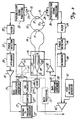
- Figure 2 shows an embodiment of the present invention in which an error reducing arrangement has been added to the system shown in Figure 1 to provide an output signal representing the rotation rate of the sensor having errors therein substantially reduced or eliminated which would otherwise present therein due to (a) misalignment of the rotated birefringent axes on either side of the resonator splice, (b) the presence of other polarization mode coupling locations, and (c) fused coupler polarization mode differences insofar as couplings and losses associated therewith. Designations used for the various devices, transmission paths and blocks in Figure 2 are the same as those that were used in Figure 1 for the corresponding items shown there.
- FIG. 2 A system configuration alternative is shown in Figure 2 that was not shown in Figure 1 through which summer 31 can be eliminated through use of another phase modulator, 19', shown in dashed line form in integrated optic chip 16 in Figure 2.
- the output of controlled serrodyne generator 27 will be directly connected to the output of amplifier 33 with summer 31 eliminated.
- the output of bias modulator generator 29 in this arrangement follows a dashed line interconnection arrangement shown in Figure 2 by first being connected to the input of another amplifier, 33', to supply the necessary voltage to operate phase modulator 19'.
- the output of amplifier 33' in Figure 2 is connected by a dashed line to phase modulator 19 so that the electromagnetic waves passing therethrough are phase modulated in accordance with a signal provided by generator 29 through amplifier 33'.
- the error reducing arrangement provided in Figure 2 comprises changing ampiifier40 of Figure 1 to a summing amplifier, 40', in Figure 2 having one input connected to the output of integrator 38 to receive the laser 22 control feedback loop error signal therefrom. Further, in addition to the signal from integrator 38 being provided to summing amplifier 40', there is a another signal provided at the other input of summing amplifier 40' from the output of a mode switching generator, 50. This generator 50 output signal is in the form of a square wave voltage waveform which is combined with the output signal from integrator 38 in summing amplifier40'.
- the amplitude of the square wave signal supplied at the output of generator 50 is sufficient to cause laser 22 to oscillate back and forth between frequencies, typically between approximately the maximum amplitude frequencies, of a pair of adjacent, opposite mode resonance peaks for the clockwise electromagnetic wave in resonator coil 10.
- the frequencies in that pair of resonance peaks will be close to, or at, the frequency f o as the frequency of laser 22 is directed toward resonant values for resonator coil 10 by the output signal of integrator 38.
- Such an arrangement can substantially reduce or eliminate the errors described above coming about because of asymmetries in resonant peaks of the counterclockwise wave (and similar peaks in the clockwise wave) arising because of the misalignment of the birefringent axes in splice 13 to a rotation angle other than exactly 90°, the presence of other unwanted polarization mode coupling locations particularly in the input and output couplers, and because of differential couplings and losses in the "x" and "y" axes in the coupling from resonator coil 10 to output optical fiber 15.
- the intensities of the results of the coupling of the two resonator orthogonal polarized waves at the frequency near the first resonant lineshape, I ccw- d,1, f R1 and I ccw- d,2,fR 1 have the difference in frequency of the resonances thereof set by the difference of 2 ⁇ in the denominator cosine arguments of each of the equations on the right thereof, with the first intensity being at the reference value of - ⁇ , and with the second intensity shifted to +0 therefrom.
- the intensities of the coupled results of the two resonator counterclockwise orthogonally polarized waves at the frequency f R2 near the second resonant lineshape, I ccw- d,1,f R2 and I ccw- d,2,f R2 ' have the second intensity set at the reference value -8 in the cosine arguments, and the first intensity shifted to -3 ⁇ .
- the feedback loops in the system of Figure 2 control its response to such frequency oscillation of laser 22 between frequencies f R1 and f R2 , and so will direct incremental frequency changes in the frequency of laser 22 and in the frequency of serrodyne generator 27 such that only relatively small deviations from resonance occur aside from the transitions between resonant lineshape, the effects of which will settle out well before the next transition. Any changes in ⁇ r due to rotation will also be relatively slow so that near-resonant conditions are maintained even in a dynamic situation.
- these last six equations can be validly expanded in terms of the time varying phase angles and (n an integer) in a Taylor series about a resonant frequency to evaluate the response of the system of Figure 2 to excursions in frequency therefrom.
- phase sensitive detector 37 demodulates the corresponding signals supplied by filter 35 to provide the two corresponding first harmonic signal components, V 37 - f R1 and V 37 - f R2 ' associated these frequencies.
- a constant, G ccw will be used to represent multiplying the effective gains of bias and amplification electronics 25, filter 35, and phase sensitive detector 37.
- This error signal directs that feedback loop to act and cause the counterclockwise wave in resonator coil 10 to take a frequency that permits is to be in resonance therein. Any system errors along the discriminant function are stored in integrator 39 so that they may be corrected in this feedback loop.
- a similar set of equations obtained in a similar manner characterizes the clockwise response to the oscillation of the frequency of laser 22 between frequencies f R1 and f R2 .
- a different constant, G cw characterizes the gain constants from photodetector24 through photodetector signal processing electronics 26 and filter 34, and as a result of demodulation in phase sensitive detector 36.
- the frequency excursion is only in f o in this instance, and the indices of refraction for the "x" and "y" axes are those encountered in a clockwise propagating wave in resonator coil 10 at average frequency f o (such averaging eliminating the effects of bias modulation).
- phase change will be opposite but equal in the clockwise direction to the phase change associated with the counterclockwise direction.
- bias modulation frequency for the clockwise waves is ⁇ m rather than On used in connection with the counterclockwise waves.
- the error due to the addition, or superposition, of the intensities of shifted, adjacent opposite mode resonance lineshapes is represented by the first term in the pair of single braces in this last equation with the factor 4(1-R) 2 , since no differential coupling or loss is involved therein.
- This error can be reduced by (a) increasing the resonator finesse, i.e. making R have a value closer to one, and by (b) better matching the polarization mode couplings in the counterclockwise and clockwise directions, i.e. making input and output couplers 11 and 12 more symmetrical with respect to polarization mode couplings of the waves propagating in each of these directions.
- Such couplings matching will also reduce the interference error due to the first term in the pair of single brackets, an interference term with the factor K. Sowill increasing the resonator finesse and reducing resonator coil coupling as shown by the multiplying factor outside the pair of brackets, and as will reducing the output coupler 12 differential couplings and losses, and its polarization modes couplings.
- the second term in the brackets can also be reduced by all of these steps except couplings matching.
- FIG. 1 and 2 are often termed "transmissive" resonator fiber optic gyroscope systems.
- A"reflective" resonatorfiberoptic gyroscope system is another alternative which is shown in Figure 3, and in which the errors due to asymmetries in adjacent opposite mode resonance peaks are reduced, eliminated or compensated by use of essentially the same minimization system.
- the major difference in the "reflective" resonator fiber optic gyroscope system is that there is but a single coupler optically connecting resonator 10 with the remainder of the system. That is, a coupler designated 11,12 is shown in Figure 3 which couples electromagnetic waves into resonator 10 from, and out of resonator 10 to, an external optical fiber designated 14,15, serving as both the input optical fiber and the output optical fiber for the system. This is possible because of the use of two further optical couplers, 100 and 101, which couple electromagnetic waves from external optical fiber 14,15 to photodetectors 24 and 23, respectively.
- Photodetector bias and signal processing circuits 26 and 25 then provide signals to the same kinds of feedback loop arrangements in Figure 3 as similarly designated photodetector bias and signal processing circuits do in the system of Figure 2.
- the major difference in operation here is that the electromagnetic waves reaching photodetectors 23 and 24 are not only those waves which have been circulating in resonator 10 but also corresponding portions of the input electromagnetic waves which are not coupled into resonator 10 by optical coupler 11,12.
- there are two pairs of electromagnetic waves in external fiber 14,15 with each member of each pair following a different path than the other, and with each pair reaching a corresponding one of photodetectors 23 and 24. This leads to each pair member interfering with the other in that pair in impinging on the photodetector corresponding to that pair.
- the electric field components of the electromagnetic waves reaching photodetector 23 can be represented as where E d - 23 represents the electric field component of the electromagnetic waves reaching photodetector 23, qE' in' represents the input electromagnetic radiation provided through integrated waveguide 17, E ccw represents the counterclockwise electromagnetic waves which have been coupled back into external fiber 14,15 from resonator 10, and constants C1 and c 2 represent the effects of various fractional couplings, losses, and phase delays on these electromagnetic wave components reaching photodetector 23.
- the electric field components of the electromagnetic waves reaching photodetector 24 can be represented as with E d - 24 representing the electric field component of the electromagnetic waves reaching photodetector 24, pE' in' representing the electromagnetic wave electric field component in external fiber 14,15 provided through integrated waveguide 18, E cw representing the clockwise traveling electromagnetic waves which have been coupled back into external optical fiber 14,15 from resonator 10, and constants c 3 and c 4 again representing various fractional couplings, losses and phase delays on these electromagnetic wave electric field components reaching photodetector 24.
Landscapes
- Physics & Mathematics (AREA)
- Engineering & Computer Science (AREA)
- Optics & Photonics (AREA)
- Electromagnetism (AREA)
- Power Engineering (AREA)
- General Physics & Mathematics (AREA)
- Radar, Positioning & Navigation (AREA)
- Remote Sensing (AREA)
- Gyroscopes (AREA)
Abstract
Claims (16)
un moyen d'établissement de valeur de fréquence d'oscillation (50) dont une sortie est reliée électriquement à ladite première entrée dudit moyen source (22), ledit moyen d'établissement de valeur de fréquence d'oscillation (50) étant capable, sur ladite sortie de celui-ci, de délivrer un signal de sortie suffisant pour faire que ladite source (22) dirige lesdites ondes électromagnétiques de fibre optique enroulée opposées se propageant dans l'un desdits sens opposés et étant soumises à une variation de ses fréquences par les signaux sélectionnés délivrés à une première entrée dudit moyen source (22), comme décrit précédemment, de façon à osciller avec une valeur de fréquence située sensiblement entre les fréquences qui se produisent lors des résonances de modes de polarisation opposés de ces dites ondes.
Applications Claiming Priority (3)
| Application Number | Priority Date | Filing Date | Title |
|---|---|---|---|
| US821667 | 1992-01-16 | ||
| US07/821,667 US5296912A (en) | 1992-01-16 | 1992-01-16 | RFOG rotation rate error reducer having resonator mode symmetrization |
| PCT/US1993/000718 WO1993014380A1 (fr) | 1992-01-16 | 1993-01-15 | Harmonisation symetrique de modes de resonateur |
Publications (2)
| Publication Number | Publication Date |
|---|---|
| EP0576663A1 EP0576663A1 (fr) | 1994-01-05 |
| EP0576663B1 true EP0576663B1 (fr) | 1995-11-22 |
Family
ID=25233987
Family Applications (1)
| Application Number | Title | Priority Date | Filing Date |
|---|---|---|---|
| EP93903681A Expired - Lifetime EP0576663B1 (fr) | 1992-01-16 | 1993-01-15 | Harmonisation symetrique de modes de resonateur |
Country Status (5)
| Country | Link |
|---|---|
| US (1) | US5296912A (fr) |
| EP (1) | EP0576663B1 (fr) |
| JP (1) | JP3335353B2 (fr) |
| DE (1) | DE69300849T2 (fr) |
| WO (1) | WO1993014380A1 (fr) |
Families Citing this family (28)
| Publication number | Priority date | Publication date | Assignee | Title |
|---|---|---|---|---|
| US5465149A (en) * | 1994-03-10 | 1995-11-07 | Honeywell Inc. | Lightwave phase control for reduction of resonator fiber optic gyroscope Kerr effect error |
| US7106917B2 (en) | 1998-11-13 | 2006-09-12 | Xponent Photonics Inc | Resonant optical modulators |
| US6175410B1 (en) * | 1998-12-17 | 2001-01-16 | Honeywell Inc. | Fiber optic gyroscope having modulated suppression of co-propagating and counter-propagating polarization errors |
| AU2001245287A1 (en) | 2000-02-17 | 2001-09-12 | Aleph Lightgale Corporation | Fiber-ring optical resonators |
| WO2006083691A1 (fr) * | 2005-01-28 | 2006-08-10 | Honeywell International, Inc. | Gyro à fibre optique a noyau creux |
| US8446589B2 (en) * | 2009-03-06 | 2013-05-21 | Honeywell International Inc. | Residual intensity modulation (RIM) control loop in a resonator fiber-optic gyroscope (RFOG) |
| US7864328B2 (en) | 2009-03-27 | 2011-01-04 | Honeywell International Inc. | Determination of optimum modulation amplitude to suppress modulation-distortation-induced rotation sensing errors in a fiber optic gyroscope |
| US8294900B2 (en) | 2009-04-01 | 2012-10-23 | Honeywell International Inc. | Systems and methods for resonator fiber optic gyroscope intensity modulation control |
| US8098380B2 (en) * | 2009-07-21 | 2012-01-17 | Honeywell International Inc. | Resonator fiber optic gyroscope (RFOG) with reduced bias error from high order spatial modes |
| US8085407B2 (en) * | 2009-08-12 | 2011-12-27 | Honeywell International Inc. | Resonator optical gyroscope having input beam modulation optimized for high sensitivity and low bias |
| US8223341B2 (en) * | 2010-05-28 | 2012-07-17 | Honeywell International Inc. | System and method for enhancing signal-to-noise ratio of a resonator fiber optic gyroscope |
| US8274659B2 (en) | 2010-08-30 | 2012-09-25 | Honeywell International Inc. | Resonator fiber optic gyroscopes with reduced rotation rate instability from back reflections |
| US8213019B2 (en) | 2010-09-07 | 2012-07-03 | Honeywell International Inc. | RFOG with optical heterodyning for optical signal discrimination |
| US8908187B2 (en) | 2011-11-02 | 2014-12-09 | Honeywell International Inc. | System and method for reducing errors in a resonator fiber optic gyroscope |
| US8659760B2 (en) * | 2012-04-12 | 2014-02-25 | Honeywell International Inc. | Resonator fiber optic gyroscope utilizing laser frequency combs |
| US20150022818A1 (en) * | 2012-06-08 | 2015-01-22 | The Board Of Trustees Of The Leland Stanford Junior University | Laser-driven optical gyroscope with push-pull modulation |
| US8947671B2 (en) | 2013-02-22 | 2015-02-03 | Honeywell International Inc. | Method and system for detecting optical ring resonator resonance frequencies and free spectral range to reduce the number of lasers in a resonator fiber optic gyroscope |
| US9008221B2 (en) | 2013-04-01 | 2015-04-14 | Honeywell International Inc. | Spurious frequency attenuation servo |
| US9001336B1 (en) | 2013-10-07 | 2015-04-07 | Honeywell International Inc. | Methods and apparatus of tracking/locking resonator free spectral range and its application in resonator fiber optic gyroscope |
| US9097526B1 (en) * | 2014-01-17 | 2015-08-04 | Honeywell International Inc. | Systems and methods for a polarization matched resonator fiber optic gyroscope |
| US10502585B2 (en) * | 2014-10-23 | 2019-12-10 | The Boeing Company | Gyro rate computation for an interferometric fiber optic gyro |
| RU2629704C1 (ru) * | 2016-04-14 | 2017-08-31 | Акционерное общество "Серпуховский завод "Металлист" | Способ измерения комплексных коэффициентов связи в кольцевых резонаторах лазерных гироскопов |
| WO2018057468A1 (fr) | 2016-09-20 | 2018-03-29 | The Board Of Trustees Of The Leland Stanford Junior University | Système optique et procédé utilisant une source de lumière commandée par laser ayant une modulation de bruit blanc |
| US11175140B2 (en) * | 2019-09-10 | 2021-11-16 | Honeywell International Inc. | Resonator fiber optic gyroscope with integrated photonics interface |
| US11204469B1 (en) | 2020-06-01 | 2021-12-21 | Honeywell International Inc. | Apparatus for high-efficiency fiber-to-chip coupling and mode-conversion to integrated photonics platform |
| US11231278B1 (en) | 2020-10-15 | 2022-01-25 | The Board Of Trustees Of The Leland Stanford Junior University | System and method for generating broadband spectrum by phase modulation of multiple wavelengths |
| US12492902B2 (en) | 2022-06-22 | 2025-12-09 | Honeywell International Inc. | Modulation methods and systems for non-reciprocal Kerr reduction in resonator fiber optic gyroscopes |
| DE102024202402A1 (de) * | 2024-03-14 | 2025-09-18 | Robert Bosch Gesellschaft mit beschränkter Haftung | Optische Sensorvorrichtung |
Family Cites Families (5)
| Publication number | Priority date | Publication date | Assignee | Title |
|---|---|---|---|---|
| US4514088A (en) * | 1983-04-01 | 1985-04-30 | The Charles Stark Draper Laboratory, Inc. | Single-coupler guided-wave passive resonant-ring optical-gyro instrument |
| DE3426868A1 (de) * | 1984-07-20 | 1986-01-30 | LITEF Litton Technische Werke der Hellige GmbH, 7800 Freiburg | Verfahren und einrichtung zur drehratenauslesung mittels eines passiven optischen resonators |
| US4661964A (en) * | 1985-10-02 | 1987-04-28 | Northrop Corporation | Resonant waveguide laser gyro with a switched source |
| US5018857A (en) * | 1988-09-15 | 1991-05-28 | Honeywell Inc. | Passive ring resonator gyro with polarization rotating ring path |
| CA2021073A1 (fr) * | 1989-09-07 | 1991-03-08 | Glen A. Sanders | Gyroscope serrodyne double a resonateur a fibre optique |
-
1992
- 1992-01-16 US US07/821,667 patent/US5296912A/en not_active Expired - Lifetime
-
1993
- 1993-01-15 EP EP93903681A patent/EP0576663B1/fr not_active Expired - Lifetime
- 1993-01-15 JP JP51275193A patent/JP3335353B2/ja not_active Expired - Fee Related
- 1993-01-15 DE DE69300849T patent/DE69300849T2/de not_active Expired - Fee Related
- 1993-01-15 WO PCT/US1993/000718 patent/WO1993014380A1/fr not_active Ceased
Also Published As
| Publication number | Publication date |
|---|---|
| JPH06507727A (ja) | 1994-09-01 |
| EP0576663A1 (fr) | 1994-01-05 |
| JP3335353B2 (ja) | 2002-10-15 |
| DE69300849T2 (de) | 1996-06-13 |
| DE69300849D1 (de) | 1996-01-04 |
| WO1993014380A1 (fr) | 1993-07-22 |
| US5296912A (en) | 1994-03-22 |
Similar Documents
| Publication | Publication Date | Title |
|---|---|---|
| EP0576663B1 (fr) | Harmonisation symetrique de modes de resonateur | |
| EP0749564B1 (fr) | Reduction des erreurs produites par l'effet kerr dans un gyroscope a fibres optiques a resonateur | |
| EP2293014B1 (fr) | Gyroscope optique à résonateur doté d'une modulation de faisceau d'entrée optimisée pour une sensibilité élevée et une faible polarisation | |
| EP0434767B1 (fr) | Gyroscope a resonateur annulaire passif a chemin annulaire rotatif de polarisation | |
| EP0642654B1 (fr) | Gyroscope a fibres optiques avec reduction des erreurs de couplage de modes | |
| EP3508817B1 (fr) | Gyroscope optique à fibre résonant à noyau creux | |
| US4514088A (en) | Single-coupler guided-wave passive resonant-ring optical-gyro instrument | |
| US5349441A (en) | Fiber optic gyroscope refractive index induced error compensation | |
| US6014217A (en) | Fiber optic gyroscope scattering error reduction | |
| JPH0130317B2 (fr) | ||
| EP0683889A1 (fr) | Maitrise des erreurs de decalage spectral | |
| US5384637A (en) | Fiber optic gyroscope modulation amplitude control | |
| EP0502196B1 (fr) | Appareil de mesure de la vitesse angulaire par interference optique | |
| EP0075013B1 (fr) | Detecteur de rotation de fibres optiques | |
| US5394242A (en) | Fiber optic resonant ring sensor and source | |
| US5285257A (en) | Optic rotation sensing apparatus and related method including providing synchronous detection at a phase at which the AM noise is minimized | |
| JPH0447214A (ja) | 光ファイバジャイロスコープ | |
| JPH0352003B2 (fr) | ||
| EP0501002B1 (fr) | Appareil optique pour mesurer une rotation et procédé en relation avec cet appareil | |
| JPS63138208A (ja) | 位相変調方式光フアイバジヤイロ | |
| JPS6135486B2 (fr) | ||
| Kim et al. | All-fiber-optic gyroscopes | |
| JP3271019B2 (ja) | 光ファイバジャイロ |
Legal Events
| Date | Code | Title | Description |
|---|---|---|---|
| PUAI | Public reference made under article 153(3) epc to a published international application that has entered the european phase |
Free format text: ORIGINAL CODE: 0009012 |
|
| 17P | Request for examination filed |
Effective date: 19930903 |
|
| AK | Designated contracting states |
Kind code of ref document: A1 Designated state(s): DE FR GB |
|
| 17Q | First examination report despatched |
Effective date: 19950502 |
|
| GRAA | (expected) grant |
Free format text: ORIGINAL CODE: 0009210 |
|
| AK | Designated contracting states |
Kind code of ref document: B1 Designated state(s): DE FR GB |
|
| REF | Corresponds to: |
Ref document number: 69300849 Country of ref document: DE Date of ref document: 19960104 |
|
| ET | Fr: translation filed | ||
| PLBE | No opposition filed within time limit |
Free format text: ORIGINAL CODE: 0009261 |
|
| STAA | Information on the status of an ep patent application or granted ep patent |
Free format text: STATUS: NO OPPOSITION FILED WITHIN TIME LIMIT |
|
| 26N | No opposition filed | ||
| REG | Reference to a national code |
Ref country code: GB Ref legal event code: IF02 |
|
| PGFP | Annual fee paid to national office [announced via postgrant information from national office to epo] |
Ref country code: GB Payment date: 20051209 Year of fee payment: 14 |
|
| GBPC | Gb: european patent ceased through non-payment of renewal fee |
Effective date: 20070115 |
|
| PG25 | Lapsed in a contracting state [announced via postgrant information from national office to epo] |
Ref country code: GB Free format text: LAPSE BECAUSE OF NON-PAYMENT OF DUE FEES Effective date: 20070115 |
|
| PGFP | Annual fee paid to national office [announced via postgrant information from national office to epo] |
Ref country code: DE Payment date: 20090130 Year of fee payment: 17 |
|
| PGFP | Annual fee paid to national office [announced via postgrant information from national office to epo] |
Ref country code: FR Payment date: 20090106 Year of fee payment: 17 |
|
| REG | Reference to a national code |
Ref country code: FR Ref legal event code: ST Effective date: 20100930 |
|
| PG25 | Lapsed in a contracting state [announced via postgrant information from national office to epo] |
Ref country code: FR Free format text: LAPSE BECAUSE OF NON-PAYMENT OF DUE FEES Effective date: 20100201 |
|
| PG25 | Lapsed in a contracting state [announced via postgrant information from national office to epo] |
Ref country code: DE Free format text: LAPSE BECAUSE OF NON-PAYMENT OF DUE FEES Effective date: 20100803 |
|
| P01 | Opt-out of the competence of the unified patent court (upc) registered |
Effective date: 20230525 |