EP0576729A1 - Ansaugkrümmer für eine Verbrennungskraftmaschine mit einem Zylinderkopf - Google Patents
Ansaugkrümmer für eine Verbrennungskraftmaschine mit einem Zylinderkopf Download PDFInfo
- Publication number
- EP0576729A1 EP0576729A1 EP92121543A EP92121543A EP0576729A1 EP 0576729 A1 EP0576729 A1 EP 0576729A1 EP 92121543 A EP92121543 A EP 92121543A EP 92121543 A EP92121543 A EP 92121543A EP 0576729 A1 EP0576729 A1 EP 0576729A1
- Authority
- EP
- European Patent Office
- Prior art keywords
- intake manifold
- intake
- connection
- manifold according
- cylinder head
- Prior art date
- Legal status (The legal status is an assumption and is not a legal conclusion. Google has not performed a legal analysis and makes no representation as to the accuracy of the status listed.)
- Granted
Links
- 238000002485 combustion reaction Methods 0.000 title claims abstract description 21
- 239000000463 material Substances 0.000 claims description 9
- 239000013536 elastomeric material Substances 0.000 claims description 6
- 238000009423 ventilation Methods 0.000 claims description 4
- 239000002184 metal Substances 0.000 claims description 3
- 239000007789 gas Substances 0.000 description 12
- 238000004519 manufacturing process Methods 0.000 description 7
- 230000035508 accumulation Effects 0.000 description 4
- 238000009825 accumulation Methods 0.000 description 4
- 238000005516 engineering process Methods 0.000 description 2
- 229910001369 Brass Inorganic materials 0.000 description 1
- 230000005540 biological transmission Effects 0.000 description 1
- 239000010951 brass Substances 0.000 description 1
- 238000010276 construction Methods 0.000 description 1
- 230000006735 deficit Effects 0.000 description 1
- 238000009434 installation Methods 0.000 description 1
- 239000007788 liquid Substances 0.000 description 1
- 238000012423 maintenance Methods 0.000 description 1
- 239000007769 metal material Substances 0.000 description 1
- 239000000203 mixture Substances 0.000 description 1
- 238000007789 sealing Methods 0.000 description 1
- 230000007704 transition Effects 0.000 description 1
Images

Classifications
-
- F—MECHANICAL ENGINEERING; LIGHTING; HEATING; WEAPONS; BLASTING
- F02—COMBUSTION ENGINES; HOT-GAS OR COMBUSTION-PRODUCT ENGINE PLANTS
- F02M—SUPPLYING COMBUSTION ENGINES IN GENERAL WITH COMBUSTIBLE MIXTURES OR CONSTITUENTS THEREOF
- F02M35/00—Combustion-air cleaners, air intakes, intake silencers, or induction systems specially adapted for, or arranged on, internal-combustion engines
- F02M35/10—Air intakes; Induction systems
- F02M35/104—Intake manifolds
- F02M35/112—Intake manifolds for engines with cylinders all in one line
-
- F—MECHANICAL ENGINEERING; LIGHTING; HEATING; WEAPONS; BLASTING
- F02—COMBUSTION ENGINES; HOT-GAS OR COMBUSTION-PRODUCT ENGINE PLANTS
- F02M—SUPPLYING COMBUSTION ENGINES IN GENERAL WITH COMBUSTIBLE MIXTURES OR CONSTITUENTS THEREOF
- F02M35/00—Combustion-air cleaners, air intakes, intake silencers, or induction systems specially adapted for, or arranged on, internal-combustion engines
- F02M35/10—Air intakes; Induction systems
- F02M35/10006—Air intakes; Induction systems characterised by the position of elements of the air intake system in direction of the air intake flow, i.e. between ambient air inlet and supply to the combustion chamber
- F02M35/10078—Connections of intake systems to the engine
-
- F—MECHANICAL ENGINEERING; LIGHTING; HEATING; WEAPONS; BLASTING
- F02—COMBUSTION ENGINES; HOT-GAS OR COMBUSTION-PRODUCT ENGINE PLANTS
- F02M—SUPPLYING COMBUSTION ENGINES IN GENERAL WITH COMBUSTIBLE MIXTURES OR CONSTITUENTS THEREOF
- F02M35/00—Combustion-air cleaners, air intakes, intake silencers, or induction systems specially adapted for, or arranged on, internal-combustion engines
- F02M35/10—Air intakes; Induction systems
- F02M35/10091—Air intakes; Induction systems characterised by details of intake ducts: shapes; connections; arrangements
- F02M35/10131—Ducts situated in more than one plane; Ducts of one plane crossing ducts of another plane
-
- F—MECHANICAL ENGINEERING; LIGHTING; HEATING; WEAPONS; BLASTING
- F02—COMBUSTION ENGINES; HOT-GAS OR COMBUSTION-PRODUCT ENGINE PLANTS
- F02M—SUPPLYING COMBUSTION ENGINES IN GENERAL WITH COMBUSTIBLE MIXTURES OR CONSTITUENTS THEREOF
- F02M35/00—Combustion-air cleaners, air intakes, intake silencers, or induction systems specially adapted for, or arranged on, internal-combustion engines
- F02M35/10—Air intakes; Induction systems
- F02M35/10209—Fluid connections to the air intake system; their arrangement of pipes, valves or the like
- F02M35/10222—Exhaust gas recirculation [EGR]; Positive crankcase ventilation [PCV]; Additional air admission, lubricant or fuel vapour admission
-
- F—MECHANICAL ENGINEERING; LIGHTING; HEATING; WEAPONS; BLASTING
- F02—COMBUSTION ENGINES; HOT-GAS OR COMBUSTION-PRODUCT ENGINE PLANTS
- F02M—SUPPLYING COMBUSTION ENGINES IN GENERAL WITH COMBUSTIBLE MIXTURES OR CONSTITUENTS THEREOF
- F02M35/00—Combustion-air cleaners, air intakes, intake silencers, or induction systems specially adapted for, or arranged on, internal-combustion engines
- F02M35/10—Air intakes; Induction systems
- F02M35/10314—Materials for intake systems
- F02M35/10321—Plastics; Composites; Rubbers
-
- F—MECHANICAL ENGINEERING; LIGHTING; HEATING; WEAPONS; BLASTING
- F05—INDEXING SCHEMES RELATING TO ENGINES OR PUMPS IN VARIOUS SUBCLASSES OF CLASSES F01-F04
- F05C—INDEXING SCHEME RELATING TO MATERIALS, MATERIAL PROPERTIES OR MATERIAL CHARACTERISTICS FOR MACHINES, ENGINES OR PUMPS OTHER THAN NON-POSITIVE-DISPLACEMENT MACHINES OR ENGINES
- F05C2225/00—Synthetic polymers, e.g. plastics; Rubber
- F05C2225/08—Thermoplastics
Definitions
- the invention relates to an intake manifold for an internal combustion engine with a cylinder head, comprising at least one intake pipe with an intake flange for gas-tight attachment to the cylinder head, wherein a bypass line is provided for feeding a secondary gas into an intake opening of the internal combustion engine and the gas is connected to the intake port Bypass line can be fed.
- Such intake manifolds are generally known and mostly consist of a metallic material or plastic. It should be noted, however, that the secondary gas is supplied through lines that are located outside the intake manifold and that the intake manifolds have undesirable accumulations of material, particularly in the transition area between the intake pipe and the intake flange.
- the invention has for its object to further develop an intake manifold of the known type such that a bypass line for feeding a secondary gas is integrated into the component, that the intake manifold is inexpensive to manufacture in terms of production technology and economics and that undesirable material accumulations are avoided.
- the bypass line is formed by a groove of the intake flange which is open in the direction of the cylinder head and the connection is connected to one end and the intake opening to the other end of the groove.
- the advantage here is that the secondary gas is led up to the connection and then into the bypass line, which is limited on the one hand by the intake flange and on the other hand in the direction of the cylinder head.
- the gas passes through the bypass line directly into the intake pipe and thus into the internal combustion engine.
- the bypass line is preferably arranged between the intake pipe and the openings for fastening the intake manifold.
- the bypass line is particularly easy to manufacture, since the open groove in the direction of the cylinder head, like the rest of the intake manifold, can be removed from one side. Undesired material accumulations, which are unsatisfactory in terms of production technology, since they lead to different shrinkage, can be avoided in the construction and manufacture of the intake manifold according to the invention.
- the groove extends directly to the cylinder head and is sealed thereon by a flat, molded part or a liquid seal.
- the cross section of the bypass line can be optimally adapted to the particular circumstances of the application by the depth of the groove.
- the secondary gas can be vented, for example, from the crankcase of the internal combustion engine, the connection being connected to the crankcase ventilation of the internal combustion engine.
- Another application of the intake manifold can be that the hose connection is connected to an exhaust gas recirculation device or an idle charge control of the internal combustion engine.
- the secondary gases generated in these areas can be fed back into the machine and used for the combustion process.
- connection can be arranged symmetrically between the intake pipes of the intake manifold, so that the bypass line consists of at least two sections of equal length.
- the advantage here is that equal amounts of the secondary gas are fed into the intake pipes assigned to the individual cylinders and the same mixture is therefore available for all cylinders for optimal combustion.
- the partial sections of the bypass line for the two middle intake pipes can be at least partially led around them, the two outer intake pipes being connected to the connection in the relatively more direct way.
- connection can be designed as a hose connection and be made in one piece with the suction flange. This results in good sealing and good performance properties over a long period of use.
- connection can be formed by at least one opening in the cylinder head.
- the bypass line can be delimited on the side facing the cylinder head by a seal which is made of an elastomeric material.
- the elastomeric material can enclose a seal carrier, which preferably consists of a hard plastic, wherein the connection can be formed in one piece with the seal carrier.
- the seal can be positioned in the groove by an integrally molded holding device, which facilitates the assembly of the intake manifold.
- the holding device can be formed, for example, by a holding section of the seal carrier projecting in the direction of the groove, the holding section being able to be brought into engagement with the groove.
- Uniform wall thicknesses of the intake manifold and the cross section of the bypass line can be exactly maintained by using the seal, since the seal can, for example, close part of the groove open in the direction of the cylinder head with the holding device.
- the intake manifold consists of a polymeric material.
- the intake manifold is therefore easy to manufacture and has a significantly reduced weight compared to a metallic intake manifold.
- the intake flange made of plastic can have openings for fastening to the cylinder head, into which non-creeping material bushings are inserted in a non-positive and / or positive manner, are used for example made of sintered metal.
- the advantage here is that the intake manifold is permanently attached to the cylinder head and relaxation phenomena of the plastic used do not lead to an impairment of the performance properties.
- the bushes are supported on the one hand directly on the cylinder head and on the other hand on the fastening element, for example on the screw.
- the bushings can have a toothing which engages with the plastic of the intake manifold. This ensures power transmission between the bushing and flange.
- FIG. 1 a view of the intake manifold is shown;
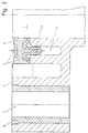
- FIG. 2 shows a detail from the intake manifold according to FIG. 1.
- FIG. 1 the view of an intake manifold for an internal combustion engine with 4 cylinders is shown, which comprises four intake pipes 1.1, 1.2, 1.3, 1.4 and an intake flange 2.
- the bypass line 3 is provided with a connection 4, which is designed as a hose connection, and is used to feed a secondary gas into the internal combustion engine.
- the connection 4 is connected to the crankcase of the internal combustion engine for ventilation.
- the bypass line 3 is formed by a groove 5 in the intake flange 2, which is open in the direction of the cylinder head for easier manufacture.
- the hose connection is formed in one piece with the intake flange 2 and connected to one end of the groove 5.
- the groove 5 extends from the connection 4 to the intake manifold 1 of the intake manifold.
- connection 4 is arranged symmetrically between the intake pipes 1.1 to 1.4 and the bypass line 3 is divided into four sections 3.1 to 3.4 of equal length.
- the two intake pipes 1.2, 1.3 closest to the connection 4 are connected to the crankcase ventilation via the sections 3.2, 3.3, which at least partially extend along the circumference of the intake pipes 1.2, 1.3.
- the sections 3.1, 3.4 of the bypass line 3, which lead from the connection 4 into the outer intake pipes 1.1, 1.4, have the same length as the adjacent sections 3.2, 3.3.
- a seal 6 made of elastomeric material is provided to seal the intake flange 2 from the cylinder head.
- the seal 6 comprises a seal carrier (9) made of a hard plastic, which is partially enclosed by elastomeric material.
- the seal carrier 9 is positioned with a projection 9.1 in the groove 5.
- the hose connection can be formed in one piece with the seal carrier 9.
- Different configurations of the seal 6, for. B. without seal carrier 9.1 when using a connection 4, which is formed by an opening in the cylinder head, are also possible.
- the groove 5 is arranged between the intake pipe 1 and the opening 7. The wall thicknesses of the intake manifold are essentially the same, so that undesirable material accumulations are avoided.
- the bushing 8 which is inserted in the opening 7 in a non-positive and / or positive manner, consists in this exemplary embodiment of brass.
- the bushing 8 has a surface structure in a partial region of its axial extent for secure fixing within the opening 7.
Landscapes
- Engineering & Computer Science (AREA)
- Chemical & Material Sciences (AREA)
- Combustion & Propulsion (AREA)
- Mechanical Engineering (AREA)
- General Engineering & Computer Science (AREA)
- Cylinder Crankcases Of Internal Combustion Engines (AREA)
- Exhaust-Gas Circulating Devices (AREA)
- Gasket Seals (AREA)
Abstract
Description
- Die Erfindung betrifft einen Ansaugkrümmer für eine Verbrennungskraftmaschine mit einem Zylinderkopf, umfassend zumindest ein Ansaugrohr mit einem Ansaugflansch zur gasdichten Befestigung an dem Zylinderkopf, wobei eine Bypassleitung zur Einspeisung eines sekundären Gases in eine Ansaugöffnung der Verbrennungskraftmaschine vorgesehen ist und wobei das Gas mittels eines Anschlusses in die Bypassleitung einspeisbar ist.
- Solche Ansaugkrümmer sind allgemein bekannt und bestehen zumeist aus einem metallischen Werkstoff oder aus Kunstsoff. Dabei ist allerdings zu beachten, daß das sekundäre Gas durch Leitungen zugeführt wird, die sich außerhalb des Ansaugkrümmers befinden und daß die Ansaugkrümmer herstellungsbedingt unerwünschte Materialanhäufungen, insbesondere im Übergangsbereich zwischen dem Ansaugrohr und dem Ansaugflansch aufweisen.
- Der Erfindung liegt die Aufgabe zugrunde, einen Ansaugkrümmer der vorbekannten Art derart weiter zu entwickeln, daß eine Bypassleitung zur Einspeisung eines sekundären Gases in das Bauteil integriert ist, daß der Ansaugkrümmer in fertigungstechnischer und wirtschaftlicher Hinsicht günstig herstellbar ist und daß unerwünschte Materialanhäufungen vermieden werden.
- Diese Aufgabe wird bei dem erfindungsgemäßen Ansaugkrümmer durch Anspruch 1 gelöst, auf vorteilhafte Ausgestaltungen nehmen die Unteransprüche Bezug.
- Im Hinblick auf eine einfache und unkomplizierte Zuführung eines sekundären Gases in die Verbrennungskraftmaschine ist die Bypassleitung durch eine in Richtung des Zylinderkopfes offene Nut des Ansaugflansches gebildet und der Anschluß ist mit dem einen Ende und die Ansaugöffnung mit dem anderen Ende der Nut verbunden. Hierbei ist von Vorteil, daß das sekundäre Gas bis an den Anschluß geführt wird und anschließend in die Bypassleitung, die einerseits durch den Ansaugflansch und andererseits in Richtung des Zylinderkopfs begrenzt ist. Durch die Bypassleitung gelangt das Gas direkt in das Ansaugrohr und somit in die Verbrennungskraftmaschine. Die Bypassleitung ist bevorzugt zwischen dem Ansaugrohr und den Durchbrechungen zur Befestigung des Ansaugkrümmers angeordnet. Die Bypassleitung ist besonders einfach herstellbar, da die in Richtung des Zylinderkopfs offene Nut, ebenso wie der Rest des Ansaugkrümmers von einer Seite entformt werden können. Unerwünschte Materialanhäufungen, die in fertigungstechnischer Hinsicht wenig befriedigend sind, da sie zu unterschiedlichem Schrumpf führen, können bei der Konstruktion und der Fertigung des erfindungsgemäßen Ansaugkrümmers vermieden werden. Im einfachsten Falle kann es vorgesehen sein, daß sich die Nut bis direkt an den Zylinderkopf erstreckt und an diesem durch eine Flach-, Formteil- oder eine Flüssigdichtung abgedichtet ist. Der Querschnitt der Bypassleitung kann den jeweiligen Gegebenheiten des Anwendungsfalls in optimaler Weise durch die Tiefe der Nut angepaßt sein.
- Das sekundäre Gas kann beispielsweise aus dem Kurbelgehäuse der Verbrennungskraftmaschine entlüftet sein, wobei der Anschluß mit der Kurbelgehäuseentlüftung der Verbrennungskraftmaschine verbunden ist.
- Eine andere Anwendung des Ansaugkrümmers kann darin bestehen, daß der Schlauchanschluß mit einer Abgasrückführvorrichtung oder einer Leerlauffüllungsregelung der Verbrennungskraftmaschine verbunden ist. Die in diesen Bereichen anfallenden, sekundären Gase können dadurch der Maschine wieder zugeführt und für den Verbrennungsablauf genutzt werden.
- Bei Verwendung des Ansaugkrümmers an mehrzylindrigen Verbrennungskraftmaschinen kann der Anschluß symmetrisch zwischen den Ansaugrohren des Ansaugkrümmers angeordnet sein, so daß die Bypassleitung aus zumindest zwei gleichlangen Teilabschnitten besteht. Hierbei ist von Vorteil, daß gleiche Mengen des sekundären Gases in die den einzelnen Zylindern zugeordneten Ansaugrohre geführt werden und dadurch für alle Zylinder das gleiche Gemisch für eine optimale Verbrennung bereitsteht. Bei einer 4-Zylinder Reihenmaschine beispielsweise und einer Anordnung des Anschlusses zwischen den beiden mittleren Ansaugrohren können die Teilabschnitte der Bypassleitung für die beiden mittleren Ansaugrohre zumindest teilweise um diese herumgeführt sein, wobei die beiden äußeren Ansaugrohre auf dem relativ direkteren Weg mit dem Anschluß verbunden sind.
- Gemäß einer vorteilhaften Ausgestaltung kann der Anschluß als Schlauchanschluß ausgebildet sein und einstückig mit dem Ansaugflansch ausgeführt sein. Eine gute Abdichtung und gute Gebrauchseigenschaften während einer langen Gebrauchsdauer sind dadurch bedingt.
- Nach einer anderen Ausgestaltung kann der Anschluß durch zumindest eine Öffnung im Zylinderkopf gebildet sein. Hierbei ist von Vorteil, daß keine zusätzliche Verschlauchung erforderlich ist, wodurch einerseits der Einbauraum der Verbrennungskraftmaschine nicht weiter begrenzt wird und andererseits Wartungs- und Kontrollarbeiten in diesem Bereich entfallen können.
- Die Bypassleitung kann auf der dem Zylinderkopf zugewandten Seite durch eine Dichtung begrenzt sein, die aus einem elastomeren Werkstoff besteht. In Abhängigkeit von den jeweiligen Gegebenheiten des Anwendungsfalls kann das elastomere Material einen Dichtungsträger umschließen, der bevorzugt aus einem Hartkunststoff besteht, wobei der Anschluß einstückig mit dem Dichtungsträger ausgebildet sein kann. Die Dichtung kann in der Nut durch eine einstückig angeformte Haltevorrichtung positioniert sein, wodurch die Montage des Ansaugkrümmers erleichtert wird.
- Die Haltevorrichtung kann beispielsweise durch einen in Richtung der Nut vorspringenden Halteabschnitt des Dichtungsträgers gebildet sein, wobei der Halteabschnitt mit der Nut in Eingriff bringbar ist.Gleichmäßige Wandstärken des Ansaugkrümmers und der Querschnitt der Bypassleitung können durch die Verwendung der Dichtung genau eingehalten werden, da die Dichtung beispielsweise mit der Haltevorrichtung einen Teil der in Richtung des Zylinderkopfes offenen Nut verschließen kann.
- Gemäß einer vorteilhaften Ausgestaltung ist es vorgesehen, daß der Ansaugkrümmer aus einem polymeren Werkstoff besteht. Der Ansaugkrümmer ist dadurch einfach herstellbar und weist im Vergleich zu einem metallischen Ansaugkrümmer ein deutlich verringertes Gewicht auf.
- Der Ansaugflansch aus Kunststoff kann zur Befestigung am Zylinderkopf Durchbrechungen aufweisen, in die kraft- und/oder formschlüssig Buchsen aus einem nicht kriechenden Material, beispielsweise aus Sintermetall eingesetzt sind. Hierbei ist von Vorteil, daß der Ansaugkrümmer dauerhaft am Zylinderkopf befestigt ist und Relaxationserscheinungen des verwendeten Kunststoffs nicht zur einer Beeinträchtigung der Gebrauchseigenschaften führen. Die Buchsen stützen sich einerseits direkt am Zylinderkopf und andererseits am Befestigungselement, beispielsweise an der Schraube ab. Die Buchsen können beispielsweise im Bereich ihrer Oberfläche eine Verzahnung aufweisen, die mit dem Kunststoff des Ansaugkrümmers in Eingriff ist. Dadurch wird die Kraftübertragung zwischen Buchse und Flansch gewährleistet.
- Ein Ausführungsbeispiel des erfindungsgemäßen Ansaugkrümmers für eine Verbrennungskraftmaschine mit einem Zylinderkopf ist nachfolgend anhand der als Anlage beigefügten Zeichnungen weiter verdeutlicht. Diese zeigen die zu berücksichtigenden Einzelkomponenten teilweise in schematischer Darstellung.
- In Figur 1 ist eine Ansicht des Ansaugkrümmers gezeigt; in Figur 2 ein Ausschnitt aus dem Ansaugkrümmer gemäß Figur 1.
- In Figur 1 ist die Ansicht eines Ansaugkrümmers für eine Verbrennungskraftmaschine mit 4 Zylindern dargestellt, der vier Ansaugrohre 1.1, 1.2, 1.3, 1.4 und einen Ansaugflansch 2 umfaßt. Die Bypassleitung 3 ist mit einem Anschluß 4, der als Schlauchanschluß ausgebildet ist, versehen und dient zur Einspeisung eines sekundären Gases in die Verbrennungskraftmaschine. In diesem Ausführungsbeispiel ist der Anschluß 4 zur Entlüftung mit dem Kurbelgehäuses der Verbrennungskraftmaschine verbunden. Die Bypassleitung 3 ist durch eine Nut 5 in Ansaugflansch 2 gebildet, die zur leichteren Herstellung in Richtung des Zylinderkopfs offen ist. Der Schlauchanschluß ist in diesem Ausführungsbeispiel einstückig mit dem Ansaugflansch 2 ausgebildet und mit dem einen Ende der Nut 5 verbunden. Die Nut 5 erstreckt sich vom Anschluß 4 bis zum Ansaugrohr 1 des Ansaugkrümmers. Der Anschluß 4 ist symmetrisch zwischen den Ansaugrohren 1.1 bis 1.4 angeordnet und die Bypassleitung 3 ist in vier gleichlange Teilabschnitte 3.1 bis 3.4 aufgeteilt. Die beiden dem Anschluß 4 am nächsten liegenden Ansaugrohre 1.2, 1.3 sind über die Teilabschnitte 3.2, 3.3, die sich zumindest teilweise entlang des Umfangs der Ansaugrohre 1.2, 1.3 erstrecken, mit der Kurbelgehäuseentlüftung verbunden. Die Teilabschnitte 3.1, 3.4 der Bypassleitung 3, die vom Anschluß 4 in die äußeren Ansaugrohre 1.1, 1.4 führen, weisen die gleiche Länge auf, wie die benachbarten Teilabschnitte 3.2, 3.3.
- Zur Abdichtung des Ansaugflanschs 2 gegenüber dem Zylinderkopf ist eine Dichtung 6 aus elastomerem Werkstoff vorgesehen. Wie in Figur 2 dargestellt, umfaßt die Dichtung 6 einen Dichtungsträger (9) aus einem Hartkunststoff, der von elastomerem Werkstoff teilweise umschlossen ist. Der Dichtungsträger 9 ist mit einem Vorsprung 9.1 in der Nut 5 positioniert. Nach einem von Figur 1 abweichenden Ausführungsbeispiel kann der Schlauchanschluß einstückig mit dem Dichtungsträger 9 ausgebildet sein. Abweichende Ausgestaltungen der Dichtung 6, z. B. ohne Dichtungsträger 9.1 bei Verwendung eines Anschlusses 4, der durch eine Öffnung im Zylinderkopf gebildet ist, sind ebenfalls möglich. Die Nut 5 ist zwischen dem Ansaugrohr 1 und der Durchbrechung 7 angeordnet. Die Wandstärken des Ansaugkrümmers sind im wesentlichen gleich, so daß unerwünschte Materialanhäufungen vermieden werden. Die Buchse 8, die in der Durchbrechung 7 kraft- und/oder formschlüssig eingesetzt ist, besteht in diesem Ausführungsbeispiel aus Messing. Die Buchse 8 weisen in einem Teilbereich ihrer axialen Erstreckung eine Oberflächenstruktur zur sicheren Festlegung innerhalb der Durchbrechung 7 auf. Die Verwendung von Buchsen 8 aus davon abweichendem, nicht kriechendem Material, wie beispielsweise Sintermetall, ist ebenfalls möglich.
Claims (14)
- Ansaugkrümmer für eine Verbrennungskraftmaschine mit einem Zylinderkopf, umfassend zumindest ein Ansaugrohr mit einem Ansaugflansch zur gasdichten Befestigung an dem Zylinderkopf, wobei eine Bypassleitung zur Einspeisung eines sekundären Gases in eine Ansaugöffnung der Verbrennungskraftmaschine vorgesehen ist und wobei das Gas mittels eines Anschlusses in die Bypassleitung einspeisbar ist, dadurch gekennzeichnet, daß die Bypassleitung (3) durch eine in Richtung des Zylinderkopfs offene Nut (5) des Ansaugflansches (2) gebildet ist und daß der Anschluß (4) mit dem einen Ende und die Ansaugöffnung mit dem anderen Ende der Nut (5) verbunden ist.
- Ansaugkrümmer nach Anspruch 1, dadurch gekennzeichnet, daß der Anschluß (4) mit der Kurbelgehäuseentlüftung der Verbrennungskraftmaschine verbunden ist.
- Ansaugkrümmer nach Anspruch 1, dadurch gekennzeichnet, daß der Anschluß (4) mit einer Abgasrückführvorrichtung verbunden ist.
- Ansaugkrümmer nach Anspruch 1, dadurch gekennzeichnet, daß der Anschluß (4) mit einer Leerlauffüllungsregelungsvorrichtung verbunden ist.
- Ansaugkrümmer nach Anspruch 1 bis 4, mit zumindest zwei Ansaugrohren, dadurch gekennzeichnet, daß der Anschluß (4) symmetrisch zwischen den Ansaugrohren (1.1, 1.2) angeordnet ist und die Bypassleitung (3) aus zumindest zwei gleichlangen Teilabschnitten (3.1, 3.2) besteht.
- Ansaugkrümmer nach Anspruch 1 bis 5, dadurch gekennzeichnet, daß der Anschluß (4) als Schlauchanschluß ausgebildet ist und daß der Schlauchanschluß einstückig mit dem Ansaugflansch (2) ausgeführt ist.
- Ansaugkrümmer nach Anspruch 1 bis 5, dadurch gekennzeichnet, daß der Anschluß (4) durch zumindest eine Öffnung im Zylinderkopf gebildet ist.
- Ansaugkrümmer nach Anspruch 1 bis 7, dadurch gekennzeichnet, daß die Bypassleitung (3) auf der dem Zylinderkopf zugewandten Seite durch eine Dichtung (6) begrenzt ist, die aus einem elastomeren Werkstoff gebildet ist.
- Ansaugkrümmer nach Anspruch 8, dadurch gekennzeichnet, daß die Dichtung (6) aus einem einen Dichtungsträger (9) umschließenden elastomeren Werkstoff gebildet ist.
- Ansaugkrümmer nach Anspruch 9, dadurch gekennzeichnet, daß der Anschluß (4) einstückig mit dem Dichtungsträger (9) ausgebildet ist.
- Ansaugkrümmer nach Anspruch 10, dadurch gekennzeichnet, daß der Dichtungsträger (9) im Bereich der Bypassleitung (3) zumindest eine Haltevorrichtung aufweist.
- Ansaugkrümmer nach Anspruch 1 bis 11, gekennzeichnet durch die Verwendung eines polymeren Werkstoffs.
- Ansaugkrümmer nach Anspruch 12, dadurch gekennzeichnet, daß der Ansaugflansch (2) zur Befestigung am Zylinderkopf Durchbrechungen (7) aufweist und daß in die Durchbrechungen (7) kraft- und/oder formschlüssig Buchsen (8) aus einem nicht kriechenden Material eingesetzt sind.
- Ansaugkrümmer nach Anspruch 13, dadurch gekennzeichnet, daß die Buchsen (8) aus einem Sintermetall bestehen.
Applications Claiming Priority (2)
| Application Number | Priority Date | Filing Date | Title |
|---|---|---|---|
| DE4221913 | 1992-07-03 | ||
| DE4221913A DE4221913C1 (de) | 1992-07-03 | 1992-07-03 | Ansaugkrümmer für eine Verbrennungskraftmaschine mit einem Zylinderkopf |
Publications (2)
| Publication Number | Publication Date |
|---|---|
| EP0576729A1 true EP0576729A1 (de) | 1994-01-05 |
| EP0576729B1 EP0576729B1 (de) | 1995-11-08 |
Family
ID=6462430
Family Applications (1)
| Application Number | Title | Priority Date | Filing Date |
|---|---|---|---|
| EP92121543A Expired - Lifetime EP0576729B1 (de) | 1992-07-03 | 1992-12-18 | Ansaugkrümmer für eine Verbrennungskraftmaschine mit einem Zylinderkopf |
Country Status (4)
| Country | Link |
|---|---|
| US (1) | US5341772A (de) |
| EP (1) | EP0576729B1 (de) |
| JP (1) | JP2643774B2 (de) |
| DE (2) | DE4221913C1 (de) |
Cited By (6)
| Publication number | Priority date | Publication date | Assignee | Title |
|---|---|---|---|---|
| DE19523870A1 (de) * | 1995-06-30 | 1997-01-02 | Mann & Hummel Filter | Ansaugeinrichtung aus thermoplastischem Kunststoff |
| DE19546545A1 (de) * | 1995-12-13 | 1997-06-19 | Knecht Filterwerke Gmbh | Saugrohrmodul |
| WO1997034081A1 (en) * | 1996-03-11 | 1997-09-18 | Siemens Electric Limited | Method and system for distributing vapors or gases to each cylinder of a multicylinder engine |
| EP1672210A3 (de) * | 2004-12-20 | 2011-06-01 | Toyota Jidosha Kabushiki Kaisha | Kunststoffgussteil |
| DE102011111124A1 (de) * | 2011-08-20 | 2013-02-21 | GM Global Technology Operations LLC (n. d. Gesetzen des Staates Delaware) | Befestigungseinrichtung zur Befestigung eines Einlasskrümmers an einem Zylinderkopf |
| CN104074645A (zh) * | 2014-07-14 | 2014-10-01 | 宁波浙成科技咨询有限公司 | 一种发动机塑料进气歧管的密封垫 |
Families Citing this family (11)
| Publication number | Priority date | Publication date | Assignee | Title |
|---|---|---|---|---|
| US5522362A (en) * | 1994-05-10 | 1996-06-04 | Sanshin Kogyo Kabushiki Kaisha | Idle control arrangement for engine |
| ES2105822T5 (es) † | 1995-07-04 | 2002-01-16 | Benteler Werke Ag | Dispositivo para el acoplamiento de tubos de escape a un bloque motor. |
| US5595151A (en) * | 1995-12-11 | 1997-01-21 | Siemens Electric Limited | Releasable connection for molded parts |
| DE19608066C1 (de) * | 1996-03-02 | 1997-06-05 | Daimler Benz Ag | Kurbelraumentlüftung für eine Brennkraftmaschine |
| DE19652748C1 (de) * | 1996-12-18 | 1997-12-18 | Bosch Gmbh Robert | Schraubhülse zur Vorzentrierung |
| DE10045636B4 (de) * | 2000-09-15 | 2012-04-12 | Audi Ag | Vorrichtung zum Führen eines sekundären Gases |
| DE10131004A1 (de) * | 2001-06-27 | 2003-01-09 | Mann & Hummel Filter | Ansaugvorrichtung für eine Brennkraftmaschine mit Kurbelgehäuseentlüftung |
| US6840204B1 (en) * | 2002-11-25 | 2005-01-11 | Hayes Lemmerz International, Inc. | Mounting system for an air intake manifold assembly |
| US7032579B2 (en) * | 2003-08-21 | 2006-04-25 | Mazda Motor Corporation | Exhaust gas recirculation device of engine |
| US8020541B2 (en) | 2009-12-15 | 2011-09-20 | GM Global Technology Operations LLC | Positive crankcase ventilation system |
| CN107061075B (zh) * | 2017-05-09 | 2019-12-31 | 安徽江淮汽车集团股份有限公司 | 一种进气歧管总成 |
Citations (4)
| Publication number | Priority date | Publication date | Assignee | Title |
|---|---|---|---|---|
| US4169471A (en) * | 1975-01-16 | 1979-10-02 | Paul August | Apparatus for the preparation of fuel mixtures for carburetors |
| GB2173857A (en) * | 1985-04-09 | 1986-10-22 | Nissan Motor | Induction system for internal combustion engine |
| DE9005249U1 (de) * | 1990-05-08 | 1990-06-21 | Oberland Mangold GmbH, 8100 Garmisch-Partenkirchen | Brennkraftmaschine |
| FR2655382A1 (fr) * | 1989-12-04 | 1991-06-07 | Peugeot | Dispositif d'introduction de gaz additionnel, tel que de l'air, dans un moteur a combustion interne et moteur equipe d'un tel dispositif. |
Family Cites Families (10)
| Publication number | Priority date | Publication date | Assignee | Title |
|---|---|---|---|---|
| US3043286A (en) * | 1957-09-18 | 1962-07-10 | Svenska Aeroplan Ab | Method and means for the equalization of the idling operation of a multiple cylinder 2-stroke cycle internal combustion engine, preferably a carburetor engine |
| JPS5252033A (en) * | 1975-10-24 | 1977-04-26 | Mitsubishi Motors Corp | Multiple-cylinder internal engine |
| JPS5482548A (en) * | 1977-12-15 | 1979-06-30 | Toshiba Corp | Bearing device |
| JPS589249B2 (ja) * | 1978-08-10 | 1983-02-19 | トヨタ自動車株式会社 | 多気筒内燃機関の吸気装置 |
| US4325346A (en) * | 1980-09-05 | 1982-04-20 | Suzuki Jidosha Kogyo Kabushiki Kaisha | Four-cycle internal combustion engine |
| JPS57104013U (de) * | 1980-12-19 | 1982-06-26 | ||
| DE3765705D1 (de) * | 1986-07-01 | 1990-11-29 | Kloeckner Humboldt Deutz Ag | Rueckfuehrleitung fuer leckgase aus dem kurbelgehaeuse. |
| JPH0234757U (de) * | 1988-08-30 | 1990-03-06 | ||
| JPH02107758U (de) * | 1989-02-14 | 1990-08-28 | ||
| DE4038509A1 (de) * | 1990-12-03 | 1992-06-11 | Mann & Hummel Filter | Ansaugverteiler fuer eine brennkraftmaschine |
-
1992
- 1992-07-03 DE DE4221913A patent/DE4221913C1/de not_active Expired - Lifetime
- 1992-12-18 EP EP92121543A patent/EP0576729B1/de not_active Expired - Lifetime
- 1992-12-18 DE DE59204268T patent/DE59204268D1/de not_active Expired - Fee Related
-
1993
- 1993-07-02 JP JP16463593A patent/JP2643774B2/ja not_active Expired - Lifetime
- 1993-07-06 US US08/088,287 patent/US5341772A/en not_active Expired - Lifetime
Patent Citations (4)
| Publication number | Priority date | Publication date | Assignee | Title |
|---|---|---|---|---|
| US4169471A (en) * | 1975-01-16 | 1979-10-02 | Paul August | Apparatus for the preparation of fuel mixtures for carburetors |
| GB2173857A (en) * | 1985-04-09 | 1986-10-22 | Nissan Motor | Induction system for internal combustion engine |
| FR2655382A1 (fr) * | 1989-12-04 | 1991-06-07 | Peugeot | Dispositif d'introduction de gaz additionnel, tel que de l'air, dans un moteur a combustion interne et moteur equipe d'un tel dispositif. |
| DE9005249U1 (de) * | 1990-05-08 | 1990-06-21 | Oberland Mangold GmbH, 8100 Garmisch-Partenkirchen | Brennkraftmaschine |
Cited By (7)
| Publication number | Priority date | Publication date | Assignee | Title |
|---|---|---|---|---|
| DE19523870A1 (de) * | 1995-06-30 | 1997-01-02 | Mann & Hummel Filter | Ansaugeinrichtung aus thermoplastischem Kunststoff |
| DE19546545A1 (de) * | 1995-12-13 | 1997-06-19 | Knecht Filterwerke Gmbh | Saugrohrmodul |
| DE19546545B4 (de) * | 1995-12-13 | 2006-01-12 | Mahle Filtersysteme Gmbh | Saugrohrmodul |
| WO1997034081A1 (en) * | 1996-03-11 | 1997-09-18 | Siemens Electric Limited | Method and system for distributing vapors or gases to each cylinder of a multicylinder engine |
| EP1672210A3 (de) * | 2004-12-20 | 2011-06-01 | Toyota Jidosha Kabushiki Kaisha | Kunststoffgussteil |
| DE102011111124A1 (de) * | 2011-08-20 | 2013-02-21 | GM Global Technology Operations LLC (n. d. Gesetzen des Staates Delaware) | Befestigungseinrichtung zur Befestigung eines Einlasskrümmers an einem Zylinderkopf |
| CN104074645A (zh) * | 2014-07-14 | 2014-10-01 | 宁波浙成科技咨询有限公司 | 一种发动机塑料进气歧管的密封垫 |
Also Published As
| Publication number | Publication date |
|---|---|
| DE59204268D1 (de) | 1995-12-14 |
| US5341772A (en) | 1994-08-30 |
| DE4221913C1 (de) | 1994-01-27 |
| JP2643774B2 (ja) | 1997-08-20 |
| EP0576729B1 (de) | 1995-11-08 |
| JPH0674113A (ja) | 1994-03-15 |
Similar Documents
| Publication | Publication Date | Title |
|---|---|---|
| EP0576729B1 (de) | Ansaugkrümmer für eine Verbrennungskraftmaschine mit einem Zylinderkopf | |
| EP0489238B1 (de) | Ansaugverteiler für eine Brennkraftmaschine | |
| DE19735133B4 (de) | Ventilaufbau für einen Verbrennungsmotor | |
| DE69708598T2 (de) | Brennstoffeinspritzventilbefestigung für geformte einlasskrümmer mit integrierter brennstoffleitung | |
| DE19614313B4 (de) | Saugrohranlage einer Brennkraftmaschine | |
| EP1122421A2 (de) | Saugrohr mit integrierter Abgasrückführung | |
| DE4418001A1 (de) | Saugrohranordnung für eine Brennkraftmaschine mit zylinderindividuellen bogenförmigen Saugrohren | |
| DE102007062347B4 (de) | Kühlanordnung für einen Zylinderkopf einer Brennkraftmaschine | |
| DE19614474B4 (de) | Luftansaugkanalsystem für Brennkraftmaschinen | |
| DE4241759C1 (de) | Dichtung zur gasdichten Befestigung eines Ansaugkrümmers am Zylinderkopf einer Verbrennungskraftmaschine | |
| DE10100934C1 (de) | Anordnung zur gasdichten Befestigung eines einen Verbindungsflansch aufweisenden Ansaugkrümmers am Zylinderkopf einer Verbrennungskraftmaschine | |
| EP1270917B1 (de) | Zwischenflanschsystem für eine direkteinspritzende Brennkraftmaschine | |
| DE3217633A1 (de) | Verbindungsleitung | |
| DE60016895T2 (de) | Vorrichtung für brennkraftmaschinen | |
| DE2727056A1 (de) | Einrichtung fuer gegossene motorbloecke fuer wassergekuehlte zweitaktmotoren | |
| DE29708541U1 (de) | Hubkolbenmotor mit geteilter Zylinderkopfhaube | |
| DE3730090A1 (de) | Vorrichtung zur anordnung eines vergasers an einer mit einer brennkraftmaschine ausgeruesteten arbeitsmaschine | |
| DE4438401C1 (de) | Vorrichtung zum Einblasen von Luft in ein Abgasrohr | |
| DE10041484A1 (de) | Brennkraftmaschine, insbesondere für Motorräder | |
| DE10037133A1 (de) | Kraftstoffverteilerleiste | |
| EP0327848B1 (de) | Luftansaugrohr für eine Brennkraftmaschine | |
| DE4416251C1 (de) | Auslaßkanal an einer Brennkraftmaschine | |
| EP0653550A1 (de) | Entlüftungseinrichtung einer Brennkraftmaschine | |
| DE10251359B4 (de) | Zylinderkopf einer mehrzylindrigen Brennkraftmaschine | |
| DE19936748A1 (de) | Befestigungssystem für Gehäusedeckel an Gehäusen von Kraftmaschinen |
Legal Events
| Date | Code | Title | Description |
|---|---|---|---|
| PUAI | Public reference made under article 153(3) epc to a published international application that has entered the european phase |
Free format text: ORIGINAL CODE: 0009012 |
|
| 17P | Request for examination filed |
Effective date: 19931013 |
|
| AK | Designated contracting states |
Kind code of ref document: A1 Designated state(s): DE FR GB IT SE |
|
| RAP3 | Party data changed (applicant data changed or rights of an application transferred) |
Owner name: FIRMA CARL FREUDENBERG |
|
| 17Q | First examination report despatched |
Effective date: 19940927 |
|
| GRAA | (expected) grant |
Free format text: ORIGINAL CODE: 0009210 |
|
| ITF | It: translation for a ep patent filed | ||
| RAP1 | Party data changed (applicant data changed or rights of an application transferred) |
Owner name: DOEHRING, KLAUS Owner name: FIRMA CARL FREUDENBERG |
|
| RIN1 | Information on inventor provided before grant (corrected) |
Inventor name: BOARDMAN, TOM Inventor name: ANDREWS, CHRIS Inventor name: DOEHRING, KLAUS |
|
| AK | Designated contracting states |
Kind code of ref document: B1 Designated state(s): DE FR GB IT SE |
|
| REF | Corresponds to: |
Ref document number: 59204268 Country of ref document: DE Date of ref document: 19951214 |
|
| GBT | Gb: translation of ep patent filed (gb section 77(6)(a)/1977) |
Effective date: 19951117 |
|
| ET | Fr: translation filed | ||
| PLBE | No opposition filed within time limit |
Free format text: ORIGINAL CODE: 0009261 |
|
| STAA | Information on the status of an ep patent application or granted ep patent |
Free format text: STATUS: NO OPPOSITION FILED WITHIN TIME LIMIT |
|
| 26N | No opposition filed | ||
| REG | Reference to a national code |
Ref country code: FR Ref legal event code: TP |
|
| REG | Reference to a national code |
Ref country code: GB Ref legal event code: 732E |
|
| PGFP | Annual fee paid to national office [announced via postgrant information from national office to epo] |
Ref country code: FR Payment date: 19981120 Year of fee payment: 7 |
|
| PGFP | Annual fee paid to national office [announced via postgrant information from national office to epo] |
Ref country code: SE Payment date: 19981130 Year of fee payment: 7 |
|
| PGFP | Annual fee paid to national office [announced via postgrant information from national office to epo] |
Ref country code: GB Payment date: 19981215 Year of fee payment: 7 |
|
| PGFP | Annual fee paid to national office [announced via postgrant information from national office to epo] |
Ref country code: DE Payment date: 19990519 Year of fee payment: 7 |
|
| PG25 | Lapsed in a contracting state [announced via postgrant information from national office to epo] |
Ref country code: GB Free format text: LAPSE BECAUSE OF NON-PAYMENT OF DUE FEES Effective date: 19991218 |
|
| PG25 | Lapsed in a contracting state [announced via postgrant information from national office to epo] |
Ref country code: SE Free format text: LAPSE BECAUSE OF NON-PAYMENT OF DUE FEES Effective date: 19991219 |
|
| GBPC | Gb: european patent ceased through non-payment of renewal fee |
Effective date: 19991218 |
|
| EUG | Se: european patent has lapsed |
Ref document number: 92121543.0 |
|
| PG25 | Lapsed in a contracting state [announced via postgrant information from national office to epo] |
Ref country code: FR Free format text: LAPSE BECAUSE OF NON-PAYMENT OF DUE FEES Effective date: 20000831 |
|
| PG25 | Lapsed in a contracting state [announced via postgrant information from national office to epo] |
Ref country code: DE Free format text: LAPSE BECAUSE OF NON-PAYMENT OF DUE FEES Effective date: 20001003 |
|
| REG | Reference to a national code |
Ref country code: FR Ref legal event code: ST |
|
| PG25 | Lapsed in a contracting state [announced via postgrant information from national office to epo] |
Ref country code: IT Free format text: LAPSE BECAUSE OF NON-PAYMENT OF DUE FEES;WARNING: LAPSES OF ITALIAN PATENTS WITH EFFECTIVE DATE BEFORE 2007 MAY HAVE OCCURRED AT ANY TIME BEFORE 2007. THE CORRECT EFFECTIVE DATE MAY BE DIFFERENT FROM THE ONE RECORDED. Effective date: 20051218 |