EP0576751A1 - Heisssiegeln von Schachtelzuschnitten bei der Herstellung oder dem Verschliessen von Schachteln - Google Patents
Heisssiegeln von Schachtelzuschnitten bei der Herstellung oder dem Verschliessen von Schachteln Download PDFInfo
- Publication number
- EP0576751A1 EP0576751A1 EP92306075A EP92306075A EP0576751A1 EP 0576751 A1 EP0576751 A1 EP 0576751A1 EP 92306075 A EP92306075 A EP 92306075A EP 92306075 A EP92306075 A EP 92306075A EP 0576751 A1 EP0576751 A1 EP 0576751A1
- Authority
- EP
- European Patent Office
- Prior art keywords
- nozzle
- carton
- heater
- gas
- jets
- Prior art date
- Legal status (The legal status is an assumption and is not a legal conclusion. Google has not performed a legal analysis and makes no representation as to the accuracy of the status listed.)
- Withdrawn
Links
- 238000007789 sealing Methods 0.000 title claims abstract description 30
- 238000010438 heat treatment Methods 0.000 claims abstract description 22
- 238000012856 packing Methods 0.000 claims abstract description 18
- 238000000034 method Methods 0.000 claims description 5
- 238000003780 insertion Methods 0.000 claims description 4
- 230000037431 insertion Effects 0.000 claims description 4
- 239000000463 material Substances 0.000 abstract description 7
- 238000010276 construction Methods 0.000 abstract description 2
- 239000004033 plastic Substances 0.000 description 5
- 229920003023 plastic Polymers 0.000 description 5
- 230000000694 effects Effects 0.000 description 3
- 239000011247 coating layer Substances 0.000 description 2
- 238000012986 modification Methods 0.000 description 2
- 230000004048 modification Effects 0.000 description 2
- 230000000712 assembly Effects 0.000 description 1
- 238000000429 assembly Methods 0.000 description 1
- 239000011248 coating agent Substances 0.000 description 1
- 238000000576 coating method Methods 0.000 description 1
- 238000005553 drilling Methods 0.000 description 1
- 235000015203 fruit juice Nutrition 0.000 description 1
- 239000011796 hollow space material Substances 0.000 description 1
- 230000002452 interceptive effect Effects 0.000 description 1
- 239000007788 liquid Substances 0.000 description 1
- 235000013336 milk Nutrition 0.000 description 1
- 239000008267 milk Substances 0.000 description 1
- 210000004080 milk Anatomy 0.000 description 1
- 239000011087 paperboard Substances 0.000 description 1
- 230000031070 response to heat Effects 0.000 description 1
- 235000014214 soft drink Nutrition 0.000 description 1
- 238000010792 warming Methods 0.000 description 1
Images



Classifications
-
- B—PERFORMING OPERATIONS; TRANSPORTING
- B65—CONVEYING; PACKING; STORING; HANDLING THIN OR FILAMENTARY MATERIAL
- B65B—MACHINES, APPARATUS OR DEVICES FOR, OR METHODS OF, PACKAGING ARTICLES OR MATERIALS; UNPACKING
- B65B7/00—Closing containers or receptacles after filling
- B65B7/16—Closing semi-rigid or rigid containers or receptacles not deformed by, or not taking-up shape of, contents, e.g. boxes or cartons
- B65B7/18—Closing semi-rigid or rigid containers or receptacles not deformed by, or not taking-up shape of, contents, e.g. boxes or cartons by collapsing mouth portion and subsequently folding-down or securing flaps
-
- B—PERFORMING OPERATIONS; TRANSPORTING
- B31—MAKING ARTICLES OF PAPER, CARDBOARD OR MATERIAL WORKED IN A MANNER ANALOGOUS TO PAPER; WORKING PAPER, CARDBOARD OR MATERIAL WORKED IN A MANNER ANALOGOUS TO PAPER
- B31B—MAKING CONTAINERS OF PAPER, CARDBOARD OR MATERIAL WORKED IN A MANNER ANALOGOUS TO PAPER
- B31B50/00—Making rigid or semi-rigid containers, e.g. boxes or cartons
- B31B50/60—Uniting opposed surfaces or edges; Taping
- B31B50/64—Uniting opposed surfaces or edges; Taping by applying heat or pressure, e.g. by welding
-
- B—PERFORMING OPERATIONS; TRANSPORTING
- B29—WORKING OF PLASTICS; WORKING OF SUBSTANCES IN A PLASTIC STATE IN GENERAL
- B29C—SHAPING OR JOINING OF PLASTICS; SHAPING OF MATERIAL IN A PLASTIC STATE, NOT OTHERWISE PROVIDED FOR; AFTER-TREATMENT OF THE SHAPED PRODUCTS, e.g. REPAIRING
- B29C65/00—Joining or sealing of preformed parts, e.g. welding of plastics materials; Apparatus therefor
- B29C65/02—Joining or sealing of preformed parts, e.g. welding of plastics materials; Apparatus therefor by heating, with or without pressure
- B29C65/10—Joining or sealing of preformed parts, e.g. welding of plastics materials; Apparatus therefor by heating, with or without pressure using hot gases (e.g. combustion gases) or flames coming in contact with at least one of the parts to be joined
- B29C65/103—Joining or sealing of preformed parts, e.g. welding of plastics materials; Apparatus therefor by heating, with or without pressure using hot gases (e.g. combustion gases) or flames coming in contact with at least one of the parts to be joined direct heating both surfaces to be joined
-
- B—PERFORMING OPERATIONS; TRANSPORTING
- B29—WORKING OF PLASTICS; WORKING OF SUBSTANCES IN A PLASTIC STATE IN GENERAL
- B29C—SHAPING OR JOINING OF PLASTICS; SHAPING OF MATERIAL IN A PLASTIC STATE, NOT OTHERWISE PROVIDED FOR; AFTER-TREATMENT OF THE SHAPED PRODUCTS, e.g. REPAIRING
- B29C66/00—General aspects of processes or apparatus for joining preformed parts
- B29C66/01—General aspects dealing with the joint area or with the area to be joined
- B29C66/05—Particular design of joint configurations
- B29C66/10—Particular design of joint configurations particular design of the joint cross-sections
- B29C66/11—Joint cross-sections comprising a single joint-segment, i.e. one of the parts to be joined comprising a single joint-segment in the joint cross-section
- B29C66/112—Single lapped joints
- B29C66/1122—Single lap to lap joints, i.e. overlap joints
-
- B—PERFORMING OPERATIONS; TRANSPORTING
- B29—WORKING OF PLASTICS; WORKING OF SUBSTANCES IN A PLASTIC STATE IN GENERAL
- B29C—SHAPING OR JOINING OF PLASTICS; SHAPING OF MATERIAL IN A PLASTIC STATE, NOT OTHERWISE PROVIDED FOR; AFTER-TREATMENT OF THE SHAPED PRODUCTS, e.g. REPAIRING
- B29C66/00—General aspects of processes or apparatus for joining preformed parts
- B29C66/40—General aspects of joining substantially flat articles, e.g. plates, sheets or web-like materials; Making flat seams in tubular or hollow articles; Joining single elements to substantially flat surfaces
- B29C66/41—Joining substantially flat articles ; Making flat seams in tubular or hollow articles
- B29C66/43—Joining a relatively small portion of the surface of said articles
- B29C66/431—Joining the articles to themselves
- B29C66/4312—Joining the articles to themselves for making flat seams in tubular or hollow articles, e.g. transversal seams
- B29C66/43121—Closing the ends of tubular or hollow single articles, e.g. closing the ends of bags
- B29C66/43122—Closing the top of gable top containers
-
- B—PERFORMING OPERATIONS; TRANSPORTING
- B29—WORKING OF PLASTICS; WORKING OF SUBSTANCES IN A PLASTIC STATE IN GENERAL
- B29C—SHAPING OR JOINING OF PLASTICS; SHAPING OF MATERIAL IN A PLASTIC STATE, NOT OTHERWISE PROVIDED FOR; AFTER-TREATMENT OF THE SHAPED PRODUCTS, e.g. REPAIRING
- B29C66/00—General aspects of processes or apparatus for joining preformed parts
- B29C66/40—General aspects of joining substantially flat articles, e.g. plates, sheets or web-like materials; Making flat seams in tubular or hollow articles; Joining single elements to substantially flat surfaces
- B29C66/41—Joining substantially flat articles ; Making flat seams in tubular or hollow articles
- B29C66/43—Joining a relatively small portion of the surface of said articles
- B29C66/432—Joining a relatively small portion of the surface of said articles for making tubular articles or closed loops, e.g. by joining several sheets ; for making hollow articles or hollow preforms
- B29C66/4322—Joining a relatively small portion of the surface of said articles for making tubular articles or closed loops, e.g. by joining several sheets ; for making hollow articles or hollow preforms by joining a single sheet to itself
-
- B—PERFORMING OPERATIONS; TRANSPORTING
- B29—WORKING OF PLASTICS; WORKING OF SUBSTANCES IN A PLASTIC STATE IN GENERAL
- B29C—SHAPING OR JOINING OF PLASTICS; SHAPING OF MATERIAL IN A PLASTIC STATE, NOT OTHERWISE PROVIDED FOR; AFTER-TREATMENT OF THE SHAPED PRODUCTS, e.g. REPAIRING
- B29C66/00—General aspects of processes or apparatus for joining preformed parts
- B29C66/80—General aspects of machine operations or constructions and parts thereof
-
- B—PERFORMING OPERATIONS; TRANSPORTING
- B65—CONVEYING; PACKING; STORING; HANDLING THIN OR FILAMENTARY MATERIAL
- B65B—MACHINES, APPARATUS OR DEVICES FOR, OR METHODS OF, PACKAGING ARTICLES OR MATERIALS; UNPACKING
- B65B51/00—Devices for, or methods of, sealing or securing package folds or closures; Devices for gathering or twisting wrappers, or necks of bags
- B65B51/10—Applying or generating heat or pressure or combinations thereof
- B65B51/20—Applying or generating heat or pressure or combinations thereof by fluid pressure acting directly on folds or on opposed surfaces, e.g. using hot-air jets
-
- B—PERFORMING OPERATIONS; TRANSPORTING
- B29—WORKING OF PLASTICS; WORKING OF SUBSTANCES IN A PLASTIC STATE IN GENERAL
- B29C—SHAPING OR JOINING OF PLASTICS; SHAPING OF MATERIAL IN A PLASTIC STATE, NOT OTHERWISE PROVIDED FOR; AFTER-TREATMENT OF THE SHAPED PRODUCTS, e.g. REPAIRING
- B29C66/00—General aspects of processes or apparatus for joining preformed parts
- B29C66/01—General aspects dealing with the joint area or with the area to be joined
- B29C66/05—Particular design of joint configurations
- B29C66/10—Particular design of joint configurations particular design of the joint cross-sections
- B29C66/13—Single flanged joints; Fin-type joints; Single hem joints; Edge joints; Interpenetrating fingered joints; Other specific particular designs of joint cross-sections not provided for in groups B29C66/11 - B29C66/12
- B29C66/131—Single flanged joints, i.e. one of the parts to be joined being rigid and flanged in the joint area
- B29C66/1312—Single flange to flange joints, the parts to be joined being rigid
-
- B—PERFORMING OPERATIONS; TRANSPORTING
- B29—WORKING OF PLASTICS; WORKING OF SUBSTANCES IN A PLASTIC STATE IN GENERAL
- B29C—SHAPING OR JOINING OF PLASTICS; SHAPING OF MATERIAL IN A PLASTIC STATE, NOT OTHERWISE PROVIDED FOR; AFTER-TREATMENT OF THE SHAPED PRODUCTS, e.g. REPAIRING
- B29C66/00—General aspects of processes or apparatus for joining preformed parts
- B29C66/70—General aspects of processes or apparatus for joining preformed parts characterised by the composition, physical properties or the structure of the material of the parts to be joined; Joining with non-plastics material
- B29C66/72—General aspects of processes or apparatus for joining preformed parts characterised by the composition, physical properties or the structure of the material of the parts to be joined; Joining with non-plastics material characterised by the structure of the material of the parts to be joined
- B29C66/723—General aspects of processes or apparatus for joining preformed parts characterised by the composition, physical properties or the structure of the material of the parts to be joined; Joining with non-plastics material characterised by the structure of the material of the parts to be joined being multi-layered
- B29C66/7232—General aspects of processes or apparatus for joining preformed parts characterised by the composition, physical properties or the structure of the material of the parts to be joined; Joining with non-plastics material characterised by the structure of the material of the parts to be joined being multi-layered comprising a non-plastics layer
- B29C66/72327—General aspects of processes or apparatus for joining preformed parts characterised by the composition, physical properties or the structure of the material of the parts to be joined; Joining with non-plastics material characterised by the structure of the material of the parts to be joined being multi-layered comprising a non-plastics layer consisting of natural products or their composites, not provided for in B29C66/72321 - B29C66/72324
- B29C66/72328—Paper
-
- B—PERFORMING OPERATIONS; TRANSPORTING
- B29—WORKING OF PLASTICS; WORKING OF SUBSTANCES IN A PLASTIC STATE IN GENERAL
- B29L—INDEXING SCHEME ASSOCIATED WITH SUBCLASS B29C, RELATING TO PARTICULAR ARTICLES
- B29L2031/00—Other particular articles
- B29L2031/712—Containers; Packaging elements or accessories, Packages
- B29L2031/7162—Boxes, cartons, cases
- B29L2031/7166—Cartons of the fruit juice or milk type, i.e. containers of polygonal cross sections formed by folding blanks into a tubular body with end-closing or contents-supporting elements, e.g. gable type containers
Definitions
- the present invention relates to the heat sealing of carton blanks in the construction or closing of cartons and, in particular, to carton packing machines including means for joining portions of the carton to one another by heat sealing, using heater nozzles to direct a flow of hot air to effect sealing of such carton blanks.
- Cartons for the packing of liquids such as milk, fruit juice and soft drinks are usually produced from plastics coated paperboard or cardboard by heat sealing the plastics coating layers together to construct the carton and to close it.
- the heat sealing operation is carried out by warming the plastics coating layers of the carton material with jets of hot air to raise the plastics coating to a heat sealing temperature before pressing together portions of the carton to be joined.
- EP-A-0028941 discloses direction heater air obliquely on to the interior carton wall surfaces and downwardly into the carton.
- a heater nozzle which takes the form of closed-ended tube having a multitude of gas jet outlets arranged in a band transversely about its periphery through which heated air supplied into the nozzle escapes and is directed on to the walls of the carton at the carton mouth.
- the jets are normally produced by drilling holes at right angles to the walls of the nozzle and the gas flow from them therefrom impinges substantially at right angles on the walls of the carton which in use lie adjacent to and parallel to the outer surface of the nozzle.
- a pouring spout is provided by a portion of a front panel of the carton which portion can be pulled forward during opening of the carton to provide the pouring spout.
- the upper margin of the pouring spout is defined by the upper edge of a shortened front panel which upper margin is sealed externally when the carton is closed during packing but must remain unsealed internally if the user is to be able to pull out the spout once the external seal has been broken.
- a front panel having a central region of reduced height is employed. Sealing of the side panels to this part of the front panel must be avoided.
- the present invention now therefore provides in a first aspect a carton packing machine comprising means for joining portions of a carton to one another by heat-sealing to close the top of said carton, which means comprises a heater having a heater nozzle for fitting inside the mouth of a carton to be closed, which nozzle has a plurality of gas outlet jets for the supply of heated gas to warm said carton portions to a sealing temperature by directing said heated gas on to said portions, which jets are arranged so as in use to be directed at an oblique angle on to said carton portion and toward said carton mouth.
- said nozzle has a proximal gas inlet end and a closed distal end for insertion into a carton mouth and comprises nozzle walls enclosing a gas passageway and further comprises a multitude of said gas outlet jets extending from said gas passageway to the external surface of said walls obliquely away from said distal end.
- the gas passageway will be closed downstream of the location of the outlet jets, e.g. at the distal end of the nozzle.
- the nozzle is generally rectangular in transverse cross-section.
- each of a pair of opposed faces of such a generally rectangular section nozzle is externally concave when viewed in transverse cross-section.
- each of said pair of opposed faces may be divided into a pair of subsidiary faces which meet at an obtuse angle along a line extending longitudinally of the nozzle, which line may lie approximately in a longitudinal mid plane of the nozzle.
- a nozzle so shaped is well adapted for use in forming the internal seal of a bellows or gable-type closure.
- said multitude of jets is arranged in a band shaped zone around at least three faces of said nozzle.
- said zone has a first portion of lesser width and a second portion of greater width, said second portions lying adjacent corresponding edges of their respective faces.
- That part of the zone that lies on the face of nozzle joining said edges and connects said second portions is of a width smaller than said greater width.
- Said lesser width may for instance be from 30 to 60 percent of said greater width.
- Said portion of greater width may occupy from 20 to 60 percent of the length of the part of the zone which lies on the respective face of the nozzle.
- the face of the nozzle joining said edges and connecting said second portions is preferably one of those which is externally concave in transverse cross-section referred to above.
- the first aspect of the invention includes a hot air nozzle for a carton packing machine which has a proximal gas inlet and a closed distal end for insertion into a carton mouth, and which is generally rectangular in transverse cross-section but in which each of a pair of opposed faces of said nozzle is externally concave when viewed in transverse cross-section, which nozzle comprises nozzle walls enclosing a gas passageway and further comprises a multitude of gas outlet jets extending from said gas passageway to the external surface of said walls and emerging obliquely away from the distal end.
- a hot air nozzle for a carton packing machine which has a proximal gas inlet and a closed distal end for insertion into a carton mouth, and which is generally rectangular in transverse cross-section but in which each of a pair of opposed faces of said nozzle is externally concave when viewed in transverse cross-section, which nozzle comprises nozzle walls enclosing a gas passageway and further comprises a multitude of gas outlet jet
- the gas jets may be arranged at an angle to the nozzle wall as it extends towards the distal end of the nozzle (measured in a plane perpendicular to the wall at the jet) of from 100 to 160°, more preferably 120 to 150°, e.g. 135°.
- the first aspect of the invention also includes a method of heating a heat sealable portion of a carton blank in closing a carton by heat sealing, which method comprises directing heated gas on to a first zone of said blank to warm said first zone to a heat sealing temperature, said first zone being bordered on one side by a second zone which contains the upper margin of a pull-out spout portion of the blank or is to be bonded to a zone which contains the upper margin of a pull-out spout portion of the blank the heating of which second zone is unwanted or to be avoided and being bordered on the opposite side by an edge of the blank or by a third zone, the heating of which can be tolerated, wherein said heated gas is discharged on to said first zone of the blank through jets directed obliquely away from said second zone and towards the said edge of the blank or said third zone.
- the upper margin of the pull-out spout portion may be defined by a slit extending across a panel of the blank or by the top edge of a panel of the blank. Cartons of this type are described in our co-pending British Patent Application No. 9103183.1 filed on 14th February 1991.
- the pouring spout may be provided by a portion of a front panel of the carton which portion can be pulled forward during opening of the carton to provide the pouring spout, in which the upper margin of the pouring spout is defined by the upper edge of a shortened front panel which upper margin is sealed externally when the carton is closed during packing but must remain unsealed internally if the user is to be able to pull out the spout once the external seal has been broken.
- the present invention now therefore provides in a second aspect a carton packing machine comprising means for joining portions of a carton to one another by heat-sealing, which means comprises a heater having at least one gas outlet jet for the supply of heated gas to warm a said carton portion to a sealing temperature by directing said heated gas on to said portion, which nozzle is provided with a shield member extending from the nozzle in the general direction of the gas flow from the said jet.
- said heater nozzle is for positioning alongside the mouth of a carton to be closed, and has a plurality of said gas jets arranged to be directed against the walls of the carton adjacent the carton mouth.
- said nozzle has a proximal gas inlet and a closed distal end and comprises nozzle walls enclosing a gas passageway and further comprises a multitude of said gas outlet jets extending from said gas passageway to the external surface of said walls.
- Said nozzle walls may include a pair of substantially planar walls which meet at an obtuse angle and comprise a band of said gas outlet jets extending from said gas passageway to the external surface of said walls.
- Said shield member preferably lies immediately adjacent said band and extends alongside a portion thereof. The shield member may lie between the said portion of the band and the inlet end of said nozzle.
- Said band may preferably have a first portion of lesser width and second and third portions of greater width, said second and third portions lying at respective ends of said first portion and said shield member extending alongside said first portion between said second and third portions of said band.
- the heat sealing machine may comprise a nozzle assembly which includes said heater nozzle as a first heater nozzle and further includes a second heater nozzle and a third heater nozzle.
- the first and third heater nozzles may be disposed one on either side of said second heater nozzle such that a carton mouth may be positioned over said second heater nozzle and between said first and third heater nozzles so as to be heated on interior surfaces by said second heater nozzle and on oppositely directed exterior surfaces of said first and third heater nozzles.
- said second nozzle may have the form of a waisted quadrilateral and said first and third nozzles may be positioned opposite the faces of the second nozzle which contain said waist.
- the said nozzle may have a multitude of gas outlet jets arranged in a band extending around approximately three quarters of the perimeter of said nozzle including that part thereof which is opposite to said third nozzle and those parts extending between said third nozzle and said first nozzle.
- Said band of gas outlet jets on said second nozzle may be relatively wide opposite said third nozzle and on each of those parts extending between said third nozzle and said first nozzle may have a relatively wide portion nearest to said third nozzle and a relatively narrow portion extending therefrom towards said first nozzle.
- Said relatively wide portions of said band in the part thereof extending between said third nozzle and said first nozzle are preferably somewhat shorter than or of approximately equal length to the relatively narrow portions, e.g. from 30 to 50 percent of the length of the narrow portions.
- the gas outlet jets in said relatively narrow portions of said band may preferably be angled to extend in use toward the mouth of a container being closed in said machine, i.e. angled away from the closed end of the nozzle.
- the second nozzle may be in accordance with the first aspect of the invention.
- the second aspect of the invention includes a hot air nozzle for a carton packing machine which has a proximal gas inlet and a closed distal end and comprises nozzle walls including a gas passageway and further comprises a multitude of gas outlet jets extending from said gas passageway to the external surface of at least one of said walls and a heat shield member extending from said nozzle in the general direction of gas flow from said jets. Preferred features of such nozzles are described above.
- the second aspect of the invention also includes a nozzle assembly which includes a heater nozzle of the invention as described above as a first heater nozzle and further includes a second heater nozzle and a third heater nozzle, wherein said first and third heater nozzles are disposed one on either side of said second heater nozzle such that a carton mouth may be positioned over said second heater nozzle and between said first and third heater nozzles so as to be heated on interior surfaces by said second heater nozzle and on oppositely directed exterior surfaces by said first and third heater nozzles.
- a nozzle assembly which includes a heater nozzle of the invention as described above as a first heater nozzle and further includes a second heater nozzle and a third heater nozzle, wherein said first and third heater nozzles are disposed one on either side of said second heater nozzle such that a carton mouth may be positioned over said second heater nozzle and between said first and third heater nozzles so as to be heated on interior surfaces by said second heater nozzle and on oppositely directed exterior surfaces by said first and third heater nozzles.
- the relatively narrow portion of the band of gas outlet jets adjacent to the shield member may be from 30 to 60 percent the width of the relatively wide portion of said band of jets.
- Those gas jets which are angled to extend toward the mouth of the carton during use may be arranged at an angle to the nozzle wall as it extends towards the distal end of the nozzle, measured in a plane perpendicular to the wall of the nozzle at the jet, of from 100 to 160°, more preferably 120 to 150°, e.g. 135°.
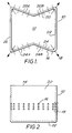
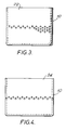
- a heater nozzle 10 according to the first aspect of the invention has a base wall 12 defining the distal end of the nozzle and side walls 20, 22, 24 and 26 extending down to said base wall 12 from an open proximal gas inlet end 14.
- the nozzle In transverse section the nozzle is seen to be generally rectangular in shape but walls 20 and 24 are rendered concave by each being divided into a pair of wall portions 20A, 20B, 24A, 24B which provide external subsidiary faces which meet at an obtuse angle along a line extending longitudinally of the nozzle and lying a mid plane of the nozzle.
- the resulting cross-sectional shape is that of a rectangle with a pinched waist.
- each of the four walls 20, 22, 24 and 26 of the nozzle there are provided a multitude of angled bores 16 forming gas outlet jets for the escape of heated air from the interior of the nozzle.
- These gas outlet jets lie in a band-shaped zone extending around the nozzle, the width of the zone varying.
- Each of the bores 16 illustrated extends upwards at an angle of 45° (135°), as measured at right-angles to the respective portion of the wall in which the bore is formed.
- the bores 16 extend at right-angles to the portion of the wall of the nozzle in which they lie, the exceptions being the groups of bores 18 which lie at the corners of the nozzle which in plan are directed at an angle bisecting the walls forming the respective corner.
- the size, number and positioning of the gas outlet jets formed by the bores 16, 18 will be selected to match the desired pattern and extent of heating of the surface of the carton material.
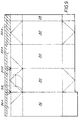
- FIG. 9 For instance if one considers the form of blank illustrated in Figure 9 in which the desired area of heating for the closing of the top of a carton formed from the blank is shaded, one sees that this pattern of heating can be obtained using the nozzle shown in Figures 1 to 6.
- the blank is divided into four main panels, namely a front panel 30, a rear panel 32, and side panels 34 and 36 separated by preformed crease lines.
- Each of these panels is in turn subdivided by transverse preformed crease lines into top forming sub-panels and bottom forming sub-panels and the top forming sub-panels are further sub-divided by transverse preformed crease lines which at the edge of the blank define sub-panels 30A, 32A, 34A and 36A used in forming a sealing fin enclosing a carton formed from the blank in a known manner.
- a slit 38 extends across most of the width of the top forming sub-panel of the front panel 30 and that part of the top forming sub-panel below the slit can in the completed carton by pulled forward during opening to form a pouring spout. To permit this to occur, it is necessary that the internal surface of the carton blank is not sealed to itself in the region of the slit 38 during the closing of the top of the blank.
- a packing machine employing the blank shown in Figure 9 will accept the blank already formed and sealed into a tube by joining its opposite side portions and will include means for forming a bottom closure employing the bottom forming sub-panels. The carton will then be filled.
- a heater nozzle of the kind shown in Figures 1 to 5 will be inserted into the mouth of the carton and hot air will be directed through the gas outlet jets of the nozzle to warm the interior surface of the carton blank in the shaded zone. It is clearly necessary to control the depth of the heated area on the fin forming sub-panels 30A, 34A and 36A with care to ensure that no seal is formed which would extend below the slit 38.
- the width of the band-shaped zone containing the gas outlet jets in the nozzle of Figures 1 to 5 is varied as follows. Over the wall 20 of the nozzle which heats the sub-panel 32A of the carton blank and zone is of a constant and relatively large width suitable to provide heating to the full depth of the fin forming portion of the blank. Across the wall 24 which serves to heat the sub-panel 30A on the front panel of the blank, the zone is of a constant relatively narrow width which is approximately half the width of the zone on the wall 20.
- the zone On the walls 22 and 26 of the nozzle which heat the fin forming sub-panels 34A and 36A of the side panels of the blank, the zone has a first portion of said lesser width extending approximately seventy percent of the way across the face of the nozzle from its junction with wall 20 of the nozzle toward its junction with wall 24 of the nozzle and a portion of said greater width occupying the remaining thirty percent of the width of the face of the nozzle and running up to the junction with wall 24 of the nozzle.
- This portion of greater width provides an increased depth of seal to catch the ends of the slit 38 to ensure good sealing of the carton in that region without interfering with the central part of the slit.
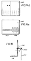
- FIG. 6 The effect of the use of angled bores to form the gas outlet jets is illustrated in Figures 6 to 8.
- the flow of hot air from the interior of the nozzle 10 is at right-angles to the nozzle wall and at right-angles to the carton blank 28.
- a significant amount of the heating air is deflected in the direction of the carton interior leading to a diffuse heating of the carton wall below the bore 16.
- the amount of heating which takes place below the bore 16 will depend upon the exact flow rate of air through the bore 16 which will in this type of machine vary from time to time so that it is difficult or impossible to obtain a precisely repeatable zone of heat sealing when the carton closure is made.
- the use of angled jets for heating the carton either on its interior or exterior walls can reduce hot air consumption by ensuring that more of the heated air delivers its heat content to areas where heat is needed and less is scattered on to adjacent areas that do not require to be heated and where heating is, for that reason if no other, to be avoided.
- the use of angled gas outlet jets can be employed to control the depth of the heated area of the fin forming sub-panels 34A and 36A to ensure that the top of the fin forming sub-panel 34A is not caught up inadvertently in the seal between the sub-panels 34A and 36A.
- a nozzle generally of the kind illustrated in the drawings but with a hole pattern designed to keep the heat away from that part of the closure when four thicknesses of the carton wall are bonded together, except for about a 6 mm length at either end of the spout forming wall.
- a hole pattern would suitably take the form on one concave face 24 of the nozzle of a narrow band of angled jets across the face of the nozzle with extra jets broadening the band adjacent or at the corners of the nozzle, the band on this face having a bottom edge in the form of a shallow inverted "u".
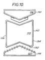
- FIG. 10 to 15 A further illustration of the first aspect of the invention is provided by the embodiment shown in Figures 10 to 15 which also serve to illustrate the second aspect of the invention.
- Each of these heater nozzles has an open proximal end and a closed distal end 116, 118 and 120 respectively.
- the heater nozzles are arranged with the first and third heater nozzles lying adjacent opposite respective sides of the second heater nozzle 112 with a gap therebetween so that the mouth of a carton may be fitted over the second heater nozzle 112 and walls of the carton will come to lie between the second heater nozzle 112 and the first and third heater nozzles 110 and 114.
- the carton may be formed from a blank as shown in Figure 11 which is adapted to form an easily opened carton.
- the blank 210 comprises front, rear and opposed side body-forming panels 212, 214, 216 and 218, conventional bottom forming panels 220 and a conventional fifth panel 222 bordering upon rear panel 214.
- the blank further comprises a top forming front panel 224 having an upper sub-panel 226. It further comprises top-forming rear and side panels 228, 230 and 232, each having a respective fin-forming upper sub panel 234, 236 and 238.
- the panels are demarcated by preformed crease lines. Additional preformed crease lines are provided for the folding of the top and the bottom of the carton. These include preformed crease lines 240 and 242 extending from the bottom corners of the top-forming front panel 224 to the centre of its upper edge where it borders the sub panel 226.
- the sub panel 226 in the top-forming front panel 224 comprises a central region 244 and flanking regions 246 and 248.
- the height of the central region is substantially less than the height of the flanking regions.
- a seal may be formed on the interior of the blank in the areas shaded in the drawings. It will be noted that the shaded area does not include any part of the central region 244 of the sub panel 226.
- the exterior faces of the flanking regions 246 and 248 as well as their internal faces are sealed together and the external faces of the two halves of the central region 224 are sealed to one another. This external seal is easily broken by pulling apart the wing portions formed by the triangular areas of the top-forming panel 224 lying below the sub panel 226.
- the top-forming front panel can then easily be popped forward as a spout having a rim provided by the top edge of the central region 244 of the sub panel 226.
- the first heater nozzle 110 of the assembly of Figure 10 is in use directed against top-forming front panel 224 of the carton.
- the first heater nozzle 10 has a multitude of gas outlet jets 122 extending from its exterior periphery to its interior hollow space and arranged in a band running across two front faces thereof which meet at an angle of 134° defining a shallow nose.
- the gas outlet jets run perpendicular to their respective faces.
- the band of outlet jets 122 can be divided into three portions, namely a first central portion 124 and first and second outer portions 126, 128. Outer portions 126 and 128 are relatively wide and the central portion 124 is relatively narrow.
- a shield member 130 in the form of a chevron shaped plate projecting from the nose of the nozzle above the central portion 124 of the band of gas outlet jets.
- the third nozzle 114 of the assembly of Figure 10 is generally similar in shape to the nozzle 110 but lacks the shield 130 and the band of the gas outlet jets 122 thereon is of constant width.
- the width of the band of nozzles is similar to that of the wider parts 126, 128 of the band on the nozzle 110.
- the second heater nozzle 112 of the assembly of the Figure 1 in plan takes the form of a waisted quadrilateral and has two opposite flat side faces and two opposite dished side faces.
- a band of gas outlet jets runs around the nozzle 112 adjacent its closed end 118.
- On the dished face 132 which faces the third heater nozzle 114 the band is relatively wide.
- the jets are directed at right angles to the face 132 with the exception of those jets lying on the corners between the face 132 and the adjacent side faces which are directed at about 45° outward to the side from the face 132.
- the band of jets On each of the two flat faces 134, 136, the band of jets has a first portion 138 of greater width and a second portion 140 of lesser width, the length of the portion 140 being slightly greater than that of the portion 138 and the width of the portion 140 being approximately one third of that of the portion 138.
- no gas outlet jets are provided except at the corner junctions between that face and the faces 132, 136 where a relatively tall column of gas outlet jets is provided which are directed at about 45° to the adjacent side faces 134, 136.
- the effect of the shield 130 is to block hot air passing through the gas outlet jets in the region 124 of the band of jets in nozzle 110 from following the dotted path in Figure 15 to reach the interior surface of the carton along the upper free edge of the central region 244 of the top-forming front panel 224 where it is important that no heat seal is inadvertently obtained. Instead, gas flow is diverted downwardly over the exterior of the wall of the carton blank 210. This improves the reliability with which an easy opening carton of the kind formed from a blank shown in Figure 11 can be sealed satisfactorily with the spout forming portion free to pull forward as the carton is opened by tearing the external seal between the surrounding portions of the carton wall.
Landscapes
- Engineering & Computer Science (AREA)
- Mechanical Engineering (AREA)
- Chemical & Material Sciences (AREA)
- Combustion & Propulsion (AREA)
- Physics & Mathematics (AREA)
- Fluid Mechanics (AREA)
- Package Closures (AREA)
- Making Paper Articles (AREA)
Applications Claiming Priority (3)
| Application Number | Priority Date | Filing Date | Title |
|---|---|---|---|
| GB9106306A GB2254285A (en) | 1991-03-25 | 1991-03-25 | Heat sealing carton blanks |
| CA002073228A CA2073228A1 (en) | 1991-03-25 | 1992-07-06 | Heat sealing of carton blanks in constructing or closing cartons |
| AU19480/92A AU1948092A (en) | 1991-03-25 | 1992-07-07 | Heat sealing of carton blanks in constructing or closing cartons |
Publications (1)
| Publication Number | Publication Date |
|---|---|
| EP0576751A1 true EP0576751A1 (de) | 1994-01-05 |
Family
ID=27152517
Family Applications (1)
| Application Number | Title | Priority Date | Filing Date |
|---|---|---|---|
| EP92306075A Withdrawn EP0576751A1 (de) | 1991-03-25 | 1992-07-01 | Heisssiegeln von Schachtelzuschnitten bei der Herstellung oder dem Verschliessen von Schachteln |
Country Status (4)
| Country | Link |
|---|---|
| EP (1) | EP0576751A1 (de) |
| AU (1) | AU1948092A (de) |
| CA (1) | CA2073228A1 (de) |
| GB (1) | GB2254285A (de) |
Cited By (2)
| Publication number | Priority date | Publication date | Assignee | Title |
|---|---|---|---|---|
| EP0995587A1 (de) * | 1998-10-20 | 2000-04-26 | Fcp (Uk) Ltd | Verbesserter Behälter und Verfahren zur seiner Herstellung |
| US10040264B2 (en) | 2015-04-01 | 2018-08-07 | Dart Container Corporation | Container bottom heater |
Families Citing this family (2)
| Publication number | Priority date | Publication date | Assignee | Title |
|---|---|---|---|---|
| US5255494A (en) * | 1991-12-10 | 1993-10-26 | Tetra Alfa Holdings S.A. | Method and apparatus for forming carton opening arrangement, and cartons made thereby |
| DE102018116273A1 (de) * | 2018-07-05 | 2020-01-09 | Precon Engineering GmbH | Vorrichtung und Verfahren zum Heißgasschweißen von Kunststoffteilen |
Citations (3)
| Publication number | Priority date | Publication date | Assignee | Title |
|---|---|---|---|---|
| US3309841A (en) * | 1964-05-18 | 1967-03-21 | Ex Cell O Corp | Selective top heater for plastic coated paperboard container packaging machines |
| US3825408A (en) * | 1973-09-07 | 1974-07-23 | Phillips Petroleum Co | Hot air heater for carton sealing machine |
| EP0526069A1 (de) * | 1991-08-01 | 1993-02-03 | Tetra Laval Holdings & Finance SA | Kartons mit balgförmigem Oberteil |
Family Cites Families (6)
| Publication number | Priority date | Publication date | Assignee | Title |
|---|---|---|---|---|
| US3239995A (en) * | 1961-06-07 | 1966-03-15 | Ex Cell O Corp | Machine for forming, filling, closing and sealing plastic coated paperboard containers |
| GB1306021A (de) * | 1971-02-12 | 1973-02-07 | ||
| EP0028941A1 (de) * | 1979-11-12 | 1981-05-20 | Novus Corp. N.V. | Verpackung |
| SE8300277L (sv) * | 1983-01-20 | 1984-07-21 | Norden Packaging Mach | Forseglingsanordning |
| SE464344B (sv) * | 1988-02-18 | 1991-04-15 | Norden Pac Dev Ab | Aendstycke, foerfarande foer dess montering paa roerformade hylsor samt anordning foer genomfoerande av foerfarandet |
| DE3841450A1 (de) * | 1988-12-09 | 1990-06-13 | Effem Gmbh | Vorrichtung zum verschliessen einer im wesentlichen aus einem schlauchabschnitt aus einem thermoplast bestehenden oeffnung |
-
1991
- 1991-03-25 GB GB9106306A patent/GB2254285A/en not_active Withdrawn
-
1992
- 1992-07-01 EP EP92306075A patent/EP0576751A1/de not_active Withdrawn
- 1992-07-06 CA CA002073228A patent/CA2073228A1/en not_active Abandoned
- 1992-07-07 AU AU19480/92A patent/AU1948092A/en not_active Abandoned
Patent Citations (3)
| Publication number | Priority date | Publication date | Assignee | Title |
|---|---|---|---|---|
| US3309841A (en) * | 1964-05-18 | 1967-03-21 | Ex Cell O Corp | Selective top heater for plastic coated paperboard container packaging machines |
| US3825408A (en) * | 1973-09-07 | 1974-07-23 | Phillips Petroleum Co | Hot air heater for carton sealing machine |
| EP0526069A1 (de) * | 1991-08-01 | 1993-02-03 | Tetra Laval Holdings & Finance SA | Kartons mit balgförmigem Oberteil |
Cited By (4)
| Publication number | Priority date | Publication date | Assignee | Title |
|---|---|---|---|---|
| EP0995587A1 (de) * | 1998-10-20 | 2000-04-26 | Fcp (Uk) Ltd | Verbesserter Behälter und Verfahren zur seiner Herstellung |
| US6312368B1 (en) | 1998-10-20 | 2001-11-06 | A & R Carton (Uk) Ltd. | Carton and method for manufacture thereof |
| US10040264B2 (en) | 2015-04-01 | 2018-08-07 | Dart Container Corporation | Container bottom heater |
| GB2538364B (en) * | 2015-04-01 | 2020-12-09 | Dart Container | Container bottom heater |
Also Published As
| Publication number | Publication date |
|---|---|
| GB2254285A (en) | 1992-10-07 |
| CA2073228A1 (en) | 1994-01-07 |
| AU1948092A (en) | 1994-01-20 |
| GB9106306D0 (en) | 1991-05-08 |
Similar Documents
| Publication | Publication Date | Title |
|---|---|---|
| US3355083A (en) | Container | |
| US4798296A (en) | Packing container provided with a reclosable opening arrangement | |
| US5069385A (en) | Cuboid gable package with a pouring spout arranged in the area of a flat top | |
| US4815655A (en) | Opening arrangement for packing containers | |
| US4946041A (en) | Easy opening gable top carton | |
| IE51631B1 (en) | Container and blank therefor | |
| EP0065846B1 (de) | Verpackung | |
| US3982683A (en) | Carton with pouring spout | |
| US4789066A (en) | Container with protective seal and tear strip | |
| US5118036A (en) | Packaging container and material for manufacture of the same | |
| JPH0379258B2 (de) | ||
| US4785993A (en) | Low stress flat end closure arrangement for thermoplastic coated paperboard carton | |
| US4601425A (en) | Nonwicking bottom closure for a liquid-tight container | |
| EP0576751A1 (de) | Heisssiegeln von Schachtelzuschnitten bei der Herstellung oder dem Verschliessen von Schachteln | |
| EP0526069B1 (de) | Kartons mit balgförmigem Oberteil | |
| JPH03148443A (ja) | 電子レンジ用容器 | |
| GB2266266A (en) | Heat sealing of carton blanks | |
| GB2260311A (en) | Heat sealed carton | |
| US4819865A (en) | Low stress flat end closure arrangement for thermoplastic coated paperboard carton | |
| JPH01267155A (ja) | 平頂容器及びそれを作成する為の素材 | |
| JPH068934A (ja) | 容器および容器を作るための半製品 | |
| JPH0680124A (ja) | カートンの組み立て又は閉鎖におけるカートンブランクのヒートシール | |
| US4570788A (en) | Packing container with fold-out pouring spout | |
| EP0277517A1 (de) | Zuschnitt mit Faltlinien für einen Behälter | |
| JPH068933A (ja) | 容器およびこれを作るための半製品 |
Legal Events
| Date | Code | Title | Description |
|---|---|---|---|
| PUAI | Public reference made under article 153(3) epc to a published international application that has entered the european phase |
Free format text: ORIGINAL CODE: 0009012 |
|
| AK | Designated contracting states |
Kind code of ref document: A1 Designated state(s): AT BE CH DE DK ES FR GR IT LI LU NL PT SE |
|
| RAP1 | Party data changed (applicant data changed or rights of an application transferred) |
Owner name: TETRA LAVAL HOLDINGS & FINANCE S.A. |
|
| STAA | Information on the status of an ep patent application or granted ep patent |
Free format text: STATUS: THE APPLICATION IS DEEMED TO BE WITHDRAWN |
|
| 18D | Application deemed to be withdrawn |
Effective date: 19940706 |