EP0576785A2 - Connecteur coaxial pour soudage à un câble semi-rigide - Google Patents
Connecteur coaxial pour soudage à un câble semi-rigide Download PDFInfo
- Publication number
- EP0576785A2 EP0576785A2 EP93103248A EP93103248A EP0576785A2 EP 0576785 A2 EP0576785 A2 EP 0576785A2 EP 93103248 A EP93103248 A EP 93103248A EP 93103248 A EP93103248 A EP 93103248A EP 0576785 A2 EP0576785 A2 EP 0576785A2
- Authority
- EP
- European Patent Office
- Prior art keywords
- conductive shell
- rearward
- cable
- retention sleeve
- outer conductive
- Prior art date
- Legal status (The legal status is an assumption and is not a legal conclusion. Google has not performed a legal analysis and makes no representation as to the accuracy of the status listed.)
- Ceased
Links
Images

Classifications
-
- H—ELECTRICITY
- H01—ELECTRIC ELEMENTS
- H01R—ELECTRICALLY-CONDUCTIVE CONNECTIONS; STRUCTURAL ASSOCIATIONS OF A PLURALITY OF MUTUALLY-INSULATED ELECTRICAL CONNECTING ELEMENTS; COUPLING DEVICES; CURRENT COLLECTORS
- H01R24/00—Two-part coupling devices, or either of their cooperating parts, characterised by their overall structure
- H01R24/38—Two-part coupling devices, or either of their cooperating parts, characterised by their overall structure having concentrically or coaxially arranged contacts
- H01R24/40—Two-part coupling devices, or either of their cooperating parts, characterised by their overall structure having concentrically or coaxially arranged contacts specially adapted for high frequency
-
- H—ELECTRICITY
- H01—ELECTRIC ELEMENTS
- H01R—ELECTRICALLY-CONDUCTIVE CONNECTIONS; STRUCTURAL ASSOCIATIONS OF A PLURALITY OF MUTUALLY-INSULATED ELECTRICAL CONNECTING ELEMENTS; COUPLING DEVICES; CURRENT COLLECTORS
- H01R13/00—Details of coupling devices of the kinds covered by groups H01R12/70 or H01R24/00 - H01R33/00
- H01R13/62—Means for facilitating engagement or disengagement of coupling parts or for holding them in engagement
- H01R13/622—Screw-ring or screw-casing
-
- H—ELECTRICITY
- H01—ELECTRIC ELEMENTS
- H01R—ELECTRICALLY-CONDUCTIVE CONNECTIONS; STRUCTURAL ASSOCIATIONS OF A PLURALITY OF MUTUALLY-INSULATED ELECTRICAL CONNECTING ELEMENTS; COUPLING DEVICES; CURRENT COLLECTORS
- H01R4/00—Electrically-conductive connections between two or more conductive members in direct contact, i.e. touching one another; Means for effecting or maintaining such contact; Electrically-conductive connections having two or more spaced connecting locations for conductors and using contact members penetrating insulation
- H01R4/02—Soldered or welded connections
- H01R4/023—Soldered or welded connections between cables or wires and terminals
- H01R4/024—Soldered or welded connections between cables or wires and terminals comprising preapplied solder
-
- H—ELECTRICITY
- H01—ELECTRIC ELEMENTS
- H01R—ELECTRICALLY-CONDUCTIVE CONNECTIONS; STRUCTURAL ASSOCIATIONS OF A PLURALITY OF MUTUALLY-INSULATED ELECTRICAL CONNECTING ELEMENTS; COUPLING DEVICES; CURRENT COLLECTORS
- H01R2103/00—Two poles
-
- H—ELECTRICITY
- H01—ELECTRIC ELEMENTS
- H01R—ELECTRICALLY-CONDUCTIVE CONNECTIONS; STRUCTURAL ASSOCIATIONS OF A PLURALITY OF MUTUALLY-INSULATED ELECTRICAL CONNECTING ELEMENTS; COUPLING DEVICES; CURRENT COLLECTORS
- H01R43/00—Apparatus or processes specially adapted for manufacturing, assembling, maintaining, or repairing of line connectors or current collectors or for joining electric conductors
- H01R43/02—Apparatus or processes specially adapted for manufacturing, assembling, maintaining, or repairing of line connectors or current collectors or for joining electric conductors for soldered or welded connections
- H01R43/0242—Apparatus or processes specially adapted for manufacturing, assembling, maintaining, or repairing of line connectors or current collectors or for joining electric conductors for soldered or welded connections comprising means for controlling the temperature, e.g. making use of the curie point
Definitions
- This relates to electrical connectors and more particularly to coaxial connectors for semirigid coaxial cable.
- Certain connectors for coaxial cable which are commercially available, include a coupling nut assembled to the outer conductive shell which threadedly couples with the outer conductive shell of a mating connector to bring together and retain the connectors in an assuredly mated condition to interconnect a coaxial cable to another like cable or to an electrical apparatus or the like.
- the connector includes an inner contact or inner conductor within a dielectric sleeve all within the outer conductive shell. The inner contact is electrically engageable with a contact terminated onto the signal conductor of the coaxial cable, which is disposed within an insulative jacket, all within an outer cable conductor.
- Certain coaxial cable has a semirigid outer conductor such as of copper alloy, and the outer conductive shell of the connector is commonly soldered to the semirigid conductor; the center conductor of the cable includes an end section extending forwardly from the cable end and is commonly received into and mated with a rearward socket section of the inner contact of the connector.
- the coupling nut is secured to the outer conductive shell in a manner permitting rotation thereabout but is stopped from axial movement therealong; the coupling nut is rotated about the first connector to become fully threaded to the mating connector, incrementally drawing the mating connector toward the first connector and its mating face firmly against the mating face of the first connector for the complementary inner and outer conductors to become electrically connected.
- the coupling nut is secured about the front section of the outer conductor and includes an inwardly directed flange at its rearward end which defines a forwardly facing surface opposing a rearwardly facing stop surface of a collar of the outer conductor to establish a forward stop.
- a crescent clip or C-clip is secured to the outer conductor, seated within an annular groove into the central section just rearwardly of the rearward end of the coupling nut, to define a forwardly facing surface opposing the rearward surface of the coupling nut to establish a rearward stop.
- An inwardly directed annular flange of the outer conductor provides a seat for the apertured rearward end of the dielectric sleeve containing the inner contact, and the rearward socket section of the inner contact is recessed within the apertured rearward end of the dielectric sleeve and just forwardly of the inwardly directed flange.
- the rearward section of the outer conductor includes a large bore adapted to receive inserted thereinto an end of the semirigid outer conductor of the cable, for soldering which is commonly performed manually.
- the present invention provides a retention sleeve for placement on the conductive shell or outer conductor of a coaxial connector and having a forward end which defines the rearward stop for coupling nut retention.
- the retention sleeve includes an inner diameter which is incrementally smaller than the outer diameter of the rearward section of the outer conductive shell to establish an interference fit with at least a portion of the rearward section.
- the retention sleeve further includes an inwardly directed annular flange at the rearward end thereof which abuts the end of the rearward shell section for controllably locating the fully assembled position of the retention sleeve on the outer conductive shell.
- the bore of the rearward section of the outer conductive shell includes a larger diameter rearward bore portion providing a seat for placement of an annular solder preform or ring thereinto prior to placement of the retention sleeve onto the outer conductive shell.
- the periphery of the aperture through the inwardly directed annular flange of the rearward end of the retention sleeve is chamfered to form a lead-in to facilitate insertion therethrough of the end of the semirigid coaxial cable.
- the retention sleeve is composed of low resistance non-magnetic metal; the outwardly facing surface of the retention sleeve includes a thin layer of high resistance magnetic material integrally joined thereonto. So fabricated, the retention sleeve defines a Curie point heater of the type disclosed in U. S. Patent No. 4,852,252.
- the connector assembly containing the solder preform therewithin receives the end of the semirigid cable into the rearward section thereof, which electrically engages the inner contact with the signal contact of the cable, and is then subjected to high frequency alternating current such as radio frequency current (RF) of 13.56 megaHertz for several seconds.
- RF radio frequency current
- the self-regulating temperature heater defined by the retention sleeve generates thermal energy until a Curie point temperature is achieved such as about 240°C, a certain amount higher than the reflow temperature such as about 183°C.
- the thermal energy reflows the solder of the preform which flows along the surface of the semirigid cable and the inwardly directed annular flange of the retention sleeve to form a solder joint between the cable's outer conductor and the retention sleeve which is assuredly electrically joined to the outer conductive shell of the connector by the interference fit.
- soldering provided for by the retention sleeve is also an objective for the soldering provided for by the retention sleeve to be controlled by an inherent maximum temperature high enough only to reflow the solder and also limited duration of application of thermal energy, thus protecting the cable insulation and the dielectric sleeve of the connector from degradation.
- a coaxial connector of the type having a coupling nut secured about an outer conductive shell and freely rotatable thereabout for threaded coupling to a complementary coaxial connector to secure the connectors together to define an electrical coaxial connection therebetween applicable to an end of a coaxial cable having a rigid outer conductor wherein a retention sleeve is insertable over a rearward section of the outer conductive shell from a rearward end thereof, the retention sleeve having a leading end defining a rearward stop for the coupling nut for retention of the coupling nut about the outer conductive shell, the retention sleeve including a body section having an inner diameter incrementally smaller than an outer diameter of the rearward section of the outer conductive shell, and the retention sleeve including an inwardly directed annular flange at a rearward end thereof engagable with the rearward end of the rearward section of the outer conductive shell, whereby during assembly when the retention sleeve is moved forwardly over the outer conductive shell from the
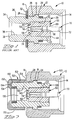
- FIG. 1 A PRIOR ART coaxial connector 10 is illustrated in FIG. 1, in which the coupling nut 12 is secured onto the forward section 22 of the conductive shell or outer conductor 20 and includes a threaded forward portion 14 for threadedly receiving a correspondingly threaded outer surface of the conductive shell or outer conductor of a mating connector (not shown).
- Coupling nut 12 includes an inwardly directed flange 16 at rearward nut end 18 which has an inner diameter less than the outer diameter of a collar 24 of outer conductor 20, so that rearwardly facing surface 26 of collar 24 defines a forward stop for coupling nut 12.
- annular groove 28 is provided circumferentially around outer conductor 20 about midway therealong between forward section 22 and rearward section 30; secured within annular groove 28 just rearwardly of rearward end 18 of coupling nut 12 is a crescent ring or C-clip 32 which establishes a rearward stop for retention of coupling nut 12 on outer conductor 20.
- a dielectric sleeve 50 is secured within forward section 22 of outer conductor 20, having a reduced diameter axial flange 52 extending rearwardly from rearward face 54 and which extends through inwardly directed flange 40 to cable-receiving bore 36.
- Profiled centered passageway 56 extends from a small diameter portion 58 through axial flange 52 forwardly to forward sleeve end 60 and an inner contact 70 is secured therewithin.
- Inner contact 70 includes a front pin section 72 extending forwardly of dielectric sleeve 50 and within threaded portion 14 of coupling nut 12 to mate with a complementary contact section of a mating connector (not shown); a socket contact section 74 is defined at the rearward end of inner contact 70 and is disposed within profiled passageway 56 aligned with small diameter passageway portion 58 to receive and mate with an end section of the inner conductor of a coaxial cable (see FIG. 4).
- Dielectric sleeve 50 is secured within outer conductor 20 by being force fit into forward cavity 42 of forward section 22 and is seated against inwardly directed annular flange 40 of outer conductor 20, after which the leading end of the outer conductor is slightly staked at 44 over the periphery of forward end 60 of dielectric sleeve 50.
- inner contact 70 is held precisely centered within the outer conductor, which has a precisely selected inside diameter in cooperation with a precisely selected outer diameter of dielectric sleeve 50 for optimum impedance performance.
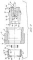
- the present invention includes a retention sleeve 150 which is placed onto rearward section 130 of outer conductive shell 120 with a body section 152 extending from leading end 154 to rearward end 156.
- An inwardly directed annular flange 158 is fabricated at rearward end 156 and defines a forwardly facing surface 160.
- Body section 152 has an inner diameter just less than the outer diameter of rearward section 130 of outer conductive shell 120 and an axial length less than that of rearward section 130, so that when retention sleeve is pushed onto rearward section 130 from rearward end 134, an interference fit is defined to retain retention sleeve 150 thereon with leading end 154 slightly spaced from end 18 of coupling nut 12, located to provide a rearward stop for coupling nut 12.
- leading end 154 includes a chamfered inner peripheral surface 162 (Fig. 2) to facilitate being received over rearward end 134 of outer conductive shell 120.
- rearward end 156 is chamfered at 164 to form a lead-in for receipt of an end of semi-rigid cable.
- the inner diameter of body section 152 of retention sleeve 150 may be selected to be about 0.002 inches (about 0.05mm) less than the outer diameter of rearward section 130 of outer conductive shell 120, so that the differenced is about 0.001 inches (about 0.025 mm).
- Retention sleeve 150 may be made by being machined from tubular stock of beryllium copper or brass or non-magnetic stainless steel, and gold plated over nickel underplating if desired.
- a further aspect of the present invention is provided by a layer of metal 170 on the outer surface 172 of body section 152 of retention sleeve which constitutes a first layer.
- Outer or second layer 170 can be intimately joined to outer surface 172 such as by cladding.
- Second layer 170 is formed from metal having high resistance and high magnetic permeability such as Alloy 42 having 42 percent nickel, 58 percent iron, for example, and of a thickness comprising at least ore skin depth for such metal, such as about 0.0015 inches (about 0.04mm) or between 0.0010 to 0.0020 inches (about 0.025mn to 0.05mm).
- First layer 152 is of a metal of low resistance and minimal magnetic permeability, such as beryllium copper.
- the bimetallic structure so formed comprises a Curie point self-regulating temperature source achieving a temperature sufficient to reflow the solder when subjected to radiofrequency current, in a manner as is generally disclosed in U. S. Patent Nos. 4,256,945 and 4,659,912.
- solder material is Sn 63 tin-lead having a reflow temperature of 183°C.
- an end portion of semirigid coaxial cable 80 is shown to include a semirigid outer conductor 82, insulative jacket 84 and inner conductor 86 having an end portion extending forwardly from end face 88 of the cable.
- FIG. 5 the end portion of cable 80 has been inserted into cable-receiving bore 136 of outer conductive shell 120 until front end 88 abuts inwardly directed flange 140, with terminal 86 comprising the cable's inner conductor is received through smaller diameter portion 58 of dielectric sleeve 50 and becomes electrically mated with socket contact section 74 of inner contact 70 of connector 100.
- Rearward section 130 of connector 100 with retention sleeve 150 thereon and containing the end portion of cable 80 inserted thereinto is placed within a coil 202 of a generator 200 of radiofrequency current such as are disclosed in U. S. Patent Nos. 4,626,767 and 4,789,767, which can produce an RF current of about 13.56 megaHertz.
- the generator is then activated for a length of time such as about 5 seconds which activates the integral Curie point heater defined by the bimetallic structure of retention sleeve 150 to generate thermal energy until the Curie temperature is achieved, above which the Curie point heater will not rise, such as 240.C.
- a temperature is achieved at outer conductor 82 of cable 80 adjacent solder preform 132 (183°C) sufficient to reflow the solder which wets along semirigid conductor 82 and forms a solder joint between the inner surface of cable-receiving bore 136 of outer conductor 82 and outer conductive shell 120 of connector 100 and also inwardly directed annular flange 158 of retention sleeve 150 forming an assured mechanical joint between the cable and the connector.
- solder resist material such as inert polyamide resin could be disposed along surfaces of annular recess 128 and rearward end 134 of outer conductive shell 120, and the forwardly facing surface of inwardly directed flange 158 of retention sleeve 150 assuring that all solder remains where desired when reflowed.
- the above mentioned connectors of the present invention can also be soldered by conventional methods such as a soldering iron if the RF supply normally used is unavailable.
Landscapes
- Coupling Device And Connection With Printed Circuit (AREA)
Applications Claiming Priority (2)
| Application Number | Priority Date | Filing Date | Title |
|---|---|---|---|
| US07/841,664 US5232377A (en) | 1992-03-03 | 1992-03-03 | Coaxial connector for soldering to semirigid cable |
| US841664 | 1992-03-03 |
Publications (2)
| Publication Number | Publication Date |
|---|---|
| EP0576785A2 true EP0576785A2 (fr) | 1994-01-05 |
| EP0576785A3 EP0576785A3 (en) | 1994-05-18 |
Family
ID=25285421
Family Applications (1)
| Application Number | Title | Priority Date | Filing Date |
|---|---|---|---|
| EP19930103248 Ceased EP0576785A3 (en) | 1992-03-03 | 1993-03-01 | Coaxial connector for soldering to semirigid cable |
Country Status (3)
| Country | Link |
|---|---|
| US (1) | US5232377A (fr) |
| EP (1) | EP0576785A3 (fr) |
| JP (1) | JPH0620749A (fr) |
Cited By (9)
| Publication number | Priority date | Publication date | Assignee | Title |
|---|---|---|---|---|
| US5802710A (en) * | 1996-10-24 | 1998-09-08 | Andrew Corporation | Method of attaching a connector to a coaxial cable and the resulting assembly |
| US5944556A (en) * | 1997-04-07 | 1999-08-31 | Andrew Corporation | Connector for coaxial cable |
| US6024609A (en) * | 1997-11-03 | 2000-02-15 | Andrew Corporation | Outer contact spring |
| EP1313170A1 (fr) * | 2001-11-17 | 2003-05-21 | Spinner GmbH Elektrotechnische Fabrik | Connecteur coaxial à soudure et méthode pour son montage sur un câble coaxial |
| WO2003061075A1 (fr) * | 2002-01-21 | 2003-07-24 | Rosenberger Hochfrequenztechnik Gmbh & Co. | Connecteur coaxial destine a la connexion soudee a un cable coaxial |
| EP1246300A3 (fr) * | 2001-03-30 | 2003-11-26 | J.S.T. Mfg. Co., Ltd. | Elément de fixation pour câble coaxial et connecteur électrique pour câble coaxial utilisant tous deux une pâte à souder à base de résine, et méthode de connexion |
| US6717065B2 (en) | 2001-03-30 | 2004-04-06 | J.S.T. Mfg. Co., Ltd. | Electric contact and an electric connector both using resin solder and a method of connecting them to a printed circuit board |
| US6818839B2 (en) | 2001-03-30 | 2004-11-16 | J.S.T. Mfg. Co., Ltd. | Electric contact and an electric connector both using resin solder and a method of connecting them to a printed circuit board |
| DE10355779B3 (de) * | 2003-11-26 | 2005-06-16 | Ims Connector Systems Gmbh | HF-Steckverbinder für Koaxialkabel |
Families Citing this family (31)
| Publication number | Priority date | Publication date | Assignee | Title |
|---|---|---|---|---|
| US5577269A (en) * | 1995-04-21 | 1996-11-19 | E. F. Johnson Company | Antenna connector for a portable radio |
| US6139364A (en) * | 1995-09-08 | 2000-10-31 | Motorola, Inc. | Apparatus for coupling RF signals |
| KR0148631B1 (ko) * | 1995-12-26 | 1998-11-16 | 양승택 | 진공용 동축 커넥터 및 그 제조방법 |
| JP2898268B1 (ja) * | 1998-02-27 | 1999-05-31 | 株式会社移動体通信先端技術研究所 | 同軸コネクタ |
| US6179656B1 (en) * | 1999-07-12 | 2001-01-30 | Shen-Chia Wong | Guide tube for coupling an end connector to a coaxial cable |
| US6183297B1 (en) * | 1999-07-29 | 2001-02-06 | Tech Lighting, L.L.C. | Coaxial connector |
| EP1182744B1 (fr) * | 2000-08-19 | 2004-07-14 | Spinner GmbH Elektrotechnische Fabrik | Asservissement de phase pour câble coaxial et connecteur associé |
| US6352448B1 (en) * | 2000-09-08 | 2002-03-05 | Randall A. Holliday | Cable TV end connector starter guide |
| US6331123B1 (en) | 2000-11-20 | 2001-12-18 | Thomas & Betts International, Inc. | Connector for hard-line coaxial cable |
| US6575786B1 (en) * | 2002-01-18 | 2003-06-10 | Adc Telecommunications, Inc. | Triaxial connector and method |
| US6667440B2 (en) * | 2002-03-06 | 2003-12-23 | Commscope Properties, Llc | Coaxial cable jumper assembly including plated outer conductor and associated methods |
| CA2428893C (fr) * | 2002-05-31 | 2007-12-18 | Thomas & Betts International, Inc. | Connecteur pour cable coaxial durable |
| US6734689B1 (en) | 2002-12-05 | 2004-05-11 | Tektronix, Inc. | Measurement probe providing signal control for an EOS/ESD protection module |
| US6731104B1 (en) | 2002-12-05 | 2004-05-04 | Tektronix, Inc. | Measurement probe system with EOS/ESD protection |
| US7156695B2 (en) * | 2002-12-06 | 2007-01-02 | Holliday Randall A | Adapter for coaxial cable with interchangeable color bands |
| US6935892B2 (en) * | 2002-12-06 | 2005-08-30 | Randall A. Holliday | Adapter for mini-coaxial cable |
| US6805583B2 (en) * | 2002-12-06 | 2004-10-19 | Randall A. Holliday | Mini-coax cable connector and method of installation |
| US7241164B2 (en) * | 2002-12-06 | 2007-07-10 | International Communication Manufacturing Corporation | Termination assembly for mini-coaxial cable having color-coded insulator |
| US6773303B1 (en) * | 2003-04-30 | 2004-08-10 | Gih Sheng Co., Ltd. | Coaxial cable having easily attached coupler |
| US7059900B2 (en) * | 2004-07-06 | 2006-06-13 | Holliday Randall A | Coaxial cable splice connector assemblies |
| US7326079B2 (en) * | 2004-07-06 | 2008-02-05 | Rhps Ventures, Llc | Mini-coaxial cable splice connector assemblies and wall mount installation tool therefor |
| US7079087B2 (en) * | 2004-09-27 | 2006-07-18 | Centurion Wireless Technologies, Inc. | Antenna joint connector |
| US7544086B1 (en) * | 2008-03-07 | 2009-06-09 | Evolution Broadband, Llc | Torque indications for coaxial connectors |
| US8425239B2 (en) | 2009-07-09 | 2013-04-23 | Tyco Electronics Corporation | Electrical connector for a solar module assembly |
| KR101139943B1 (ko) * | 2011-05-12 | 2012-04-30 | 한국전자통신연구원 | 고전압 동축케이블 및 커넥터 |
| US8984745B2 (en) | 2013-01-24 | 2015-03-24 | Andrew Llc | Soldered connector and cable interconnection method |
| CN105990744B (zh) * | 2015-01-30 | 2019-06-07 | 康普技术有限责任公司 | 包括同轴电缆和直角弯头同轴连接器的组件及其制造方法 |
| US11527846B2 (en) | 2016-02-12 | 2022-12-13 | Commscope Technologies Llc | Ganged coaxial connector assembly |
| US10950970B2 (en) | 2018-04-04 | 2021-03-16 | Commscope Technologies Llc | Ganged coaxial connector assembly |
| JP2018092844A (ja) * | 2016-12-06 | 2018-06-14 | ソニー・オリンパスメディカルソリューションズ株式会社 | 医療用同軸コネクタ、医療用同軸ケーブル、及び医療用観察システム |
| CN111989828B (zh) * | 2018-04-04 | 2022-12-02 | 康普技术有限责任公司 | 配合的连接器组件 |
Family Cites Families (22)
| Publication number | Priority date | Publication date | Assignee | Title |
|---|---|---|---|---|
| US3676573A (en) * | 1970-06-22 | 1972-07-11 | Bunker Ramo | Coaxial connector having one-piece clamp assembly |
| US3778535A (en) * | 1972-05-12 | 1973-12-11 | Amp Inc | Coaxial connector |
| US3824686A (en) * | 1972-05-12 | 1974-07-23 | Amp Inc | A method of terminating a semi-rigid coaxial cable |
| US3764959A (en) * | 1972-07-18 | 1973-10-09 | Astrolab | Universal coaxial cable connector |
| US4408821A (en) * | 1979-07-09 | 1983-10-11 | Amp Incorporated | Connector for semi-rigid coaxial cable |
| US4256945A (en) * | 1979-08-31 | 1981-03-17 | Iris Associates | Alternating current electrically resistive heating element having intrinsic temperature control |
| US4452503A (en) * | 1981-01-02 | 1984-06-05 | Amp Incorporated | Connector for semirigid coaxial cable |
| US4540231A (en) * | 1981-10-05 | 1985-09-10 | Amp | Connector for semirigid coaxial cable |
| US4447107A (en) * | 1982-03-25 | 1984-05-08 | Major Jr Frederick A | Collet for cable connector |
| US4596434A (en) * | 1983-01-21 | 1986-06-24 | M/A-Com Omni Spectra, Inc. | Solderless connectors for semi-rigid coaxial cable |
| US4583811A (en) * | 1983-03-29 | 1986-04-22 | Raychem Corporation | Mechanical coupling assembly for a coaxial cable and method of using same |
| US4688877A (en) * | 1983-08-18 | 1987-08-25 | Sealectro Corporation | Solderless coaxial connector |
| US4557546A (en) * | 1983-08-18 | 1985-12-10 | Sealectro Corporation | Solderless coaxial connector |
| US4659912A (en) * | 1984-06-21 | 1987-04-21 | Metcal, Inc. | Thin, flexible, autoregulating strap heater |
| US4626767A (en) * | 1984-12-21 | 1986-12-02 | Metcal, Inc. | Constant current r.f. generator |
| US4789767A (en) * | 1987-06-08 | 1988-12-06 | Metcal, Inc. | Autoregulating multi contact induction heater |
| US4834676A (en) * | 1988-03-01 | 1989-05-30 | Solitron Devices Incorporated | Solderless wedge-lock coaxial cable connector |
| US4852252A (en) * | 1988-11-29 | 1989-08-01 | Amp Incorporated | Method of terminating wires to terminals |
| US4921447A (en) * | 1989-05-17 | 1990-05-01 | Amp Incorporated | Terminating a shield of a malleable coaxial cable |
| US5002503A (en) * | 1989-09-08 | 1991-03-26 | Viacom International, Inc., Cable Division | Coaxial cable connector |
| US4991288A (en) * | 1989-09-29 | 1991-02-12 | Amp Incorporated | Method of terminating an electrical conductor wire |
| US5052946A (en) * | 1990-10-24 | 1991-10-01 | Haug Gmbh & Co. Kg | Plug connector for high-voltage coaxial cables |
-
1992
- 1992-03-03 US US07/841,664 patent/US5232377A/en not_active Expired - Lifetime
-
1993
- 1993-02-26 JP JP5063408A patent/JPH0620749A/ja active Pending
- 1993-03-01 EP EP19930103248 patent/EP0576785A3/en not_active Ceased
Cited By (14)
| Publication number | Priority date | Publication date | Assignee | Title |
|---|---|---|---|---|
| US5802710A (en) * | 1996-10-24 | 1998-09-08 | Andrew Corporation | Method of attaching a connector to a coaxial cable and the resulting assembly |
| EP0838880A3 (fr) * | 1996-10-24 | 1998-10-14 | Andrew A.G. | Méthode d'attachage d'un connecteur à un câble coaxial et l'assemblage ainsi formé |
| AU719956B2 (en) * | 1996-10-24 | 2000-05-18 | Andrew Corporation | Method of attaching a connector to a coaxial cable and the resulting assembly |
| US5944556A (en) * | 1997-04-07 | 1999-08-31 | Andrew Corporation | Connector for coaxial cable |
| US6024609A (en) * | 1997-11-03 | 2000-02-15 | Andrew Corporation | Outer contact spring |
| US6818839B2 (en) | 2001-03-30 | 2004-11-16 | J.S.T. Mfg. Co., Ltd. | Electric contact and an electric connector both using resin solder and a method of connecting them to a printed circuit board |
| EP1246300A3 (fr) * | 2001-03-30 | 2003-11-26 | J.S.T. Mfg. Co., Ltd. | Elément de fixation pour câble coaxial et connecteur électrique pour câble coaxial utilisant tous deux une pâte à souder à base de résine, et méthode de connexion |
| US6717065B2 (en) | 2001-03-30 | 2004-04-06 | J.S.T. Mfg. Co., Ltd. | Electric contact and an electric connector both using resin solder and a method of connecting them to a printed circuit board |
| US6974615B2 (en) | 2001-03-30 | 2005-12-13 | J.S.T. Mfg. Co., Ltd. | Binding member for coaxial cable and an electric connector for coaxial cable both using resin solder, and a method of connecting the binding member to coaxial cable or the electric connector |
| EP1313170A1 (fr) * | 2001-11-17 | 2003-05-21 | Spinner GmbH Elektrotechnische Fabrik | Connecteur coaxial à soudure et méthode pour son montage sur un câble coaxial |
| EP1724877A3 (fr) * | 2001-11-17 | 2007-07-11 | Spinner GmbH | Connecteur coaxial à soudure et méthode de montage sur un câble coaxial |
| DE10251905C5 (de) * | 2001-11-17 | 2012-06-14 | Spinner Gmbh | Lötbarer koaxialer Steckverbinder |
| WO2003061075A1 (fr) * | 2002-01-21 | 2003-07-24 | Rosenberger Hochfrequenztechnik Gmbh & Co. | Connecteur coaxial destine a la connexion soudee a un cable coaxial |
| DE10355779B3 (de) * | 2003-11-26 | 2005-06-16 | Ims Connector Systems Gmbh | HF-Steckverbinder für Koaxialkabel |
Also Published As
| Publication number | Publication date |
|---|---|
| US5232377A (en) | 1993-08-03 |
| JPH0620749A (ja) | 1994-01-28 |
| EP0576785A3 (en) | 1994-05-18 |
Similar Documents
| Publication | Publication Date | Title |
|---|---|---|
| US5232377A (en) | Coaxial connector for soldering to semirigid cable | |
| US5281167A (en) | Coaxial connector for soldering to semirigid cable | |
| US5161993A (en) | Retention sleeve for coupling nut for coaxial cable connector and method for applying same | |
| US5269701A (en) | Method for applying a retention sleeve to a coaxial cable connector | |
| US6809265B1 (en) | Terminal assembly for a coaxial cable | |
| EP0600603B1 (fr) | Ferrule pour sertissage au conducteur intérieur d'un câble coaxial | |
| EP0624933B1 (fr) | Connexion coaxiale pour un câble coaxial avec un conducteur extérieur ondulé | |
| US6848922B2 (en) | Socket contact with integrally formed arc arresting portion | |
| US5037328A (en) | Foldable dielectric insert for a coaxial contact | |
| US4861271A (en) | Right-angle coaxial plug connector | |
| US20060063438A1 (en) | Electrical connectors | |
| CA1194569A (fr) | Contact femelle pour connecteur electrique, et sa fabrication | |
| US7331821B2 (en) | Electrical connector | |
| GB2267187A (en) | Mass termination of multi-coaxial cable | |
| JPS6232585B2 (fr) | ||
| US4685761A (en) | Electrical contact assembly and method of assembly | |
| US4734051A (en) | Electrical connector butt contact | |
| GB2077053A (en) | Contact assembly incorporating retaining means | |
| US4221446A (en) | Electrical connector assembly | |
| EP0090549B1 (fr) | Assemblage d'un contact électrique | |
| US4365412A (en) | Method of making an electrical connector assembly | |
| CN214625634U (zh) | 同轴电缆组件和用于制造同轴电缆组件的设备 | |
| JPH066580Y2 (ja) | 接続端子装置 | |
| GB2109173A (en) | Connecting insulated conductors to electrical contacts | |
| GB2248731A (en) | Coaxial electrical connectors |
Legal Events
| Date | Code | Title | Description |
|---|---|---|---|
| PUAI | Public reference made under article 153(3) epc to a published international application that has entered the european phase |
Free format text: ORIGINAL CODE: 0009012 |
|
| AK | Designated contracting states |
Kind code of ref document: A2 Designated state(s): DE FR GB NL |
|
| PUAL | Search report despatched |
Free format text: ORIGINAL CODE: 0009013 |
|
| AK | Designated contracting states |
Kind code of ref document: A3 Designated state(s): DE FR GB NL |
|
| 17P | Request for examination filed |
Effective date: 19941117 |
|
| GRAG | Despatch of communication of intention to grant |
Free format text: ORIGINAL CODE: EPIDOS AGRA |
|
| 17Q | First examination report despatched |
Effective date: 19960508 |
|
| STAA | Information on the status of an ep patent application or granted ep patent |
Free format text: STATUS: THE APPLICATION HAS BEEN REFUSED |
|
| 18R | Application refused |
Effective date: 19961027 |