EP0576820B2 - Procédé et dispositif pour empiler des feuilles - Google Patents
Procédé et dispositif pour empiler des feuilles Download PDFInfo
- Publication number
- EP0576820B2 EP0576820B2 EP93107985A EP93107985A EP0576820B2 EP 0576820 B2 EP0576820 B2 EP 0576820B2 EP 93107985 A EP93107985 A EP 93107985A EP 93107985 A EP93107985 A EP 93107985A EP 0576820 B2 EP0576820 B2 EP 0576820B2
- Authority
- EP
- European Patent Office
- Prior art keywords
- stack
- bar
- sheet
- sheets
- stop board
- Prior art date
- Legal status (The legal status is an assumption and is not a legal conclusion. Google has not performed a legal analysis and makes no representation as to the accuracy of the status listed.)
- Expired - Lifetime
Links
Images

Classifications
-
- B—PERFORMING OPERATIONS; TRANSPORTING
- B65—CONVEYING; PACKING; STORING; HANDLING THIN OR FILAMENTARY MATERIAL
- B65H—HANDLING THIN OR FILAMENTARY MATERIAL, e.g. SHEETS, WEBS, CABLES
- B65H31/00—Pile receivers
- B65H31/34—Apparatus for squaring-up piled articles
- B65H31/38—Apparatus for vibrating or knocking the pile during piling
-
- B—PERFORMING OPERATIONS; TRANSPORTING
- B65—CONVEYING; PACKING; STORING; HANDLING THIN OR FILAMENTARY MATERIAL
- B65H—HANDLING THIN OR FILAMENTARY MATERIAL, e.g. SHEETS, WEBS, CABLES
- B65H31/00—Pile receivers
- B65H31/32—Auxiliary devices for receiving articles during removal of a completed pile
-
- B—PERFORMING OPERATIONS; TRANSPORTING
- B65—CONVEYING; PACKING; STORING; HANDLING THIN OR FILAMENTARY MATERIAL
- B65H—HANDLING THIN OR FILAMENTARY MATERIAL, e.g. SHEETS, WEBS, CABLES
- B65H2701/00—Handled material; Storage means
- B65H2701/10—Handled articles or webs
- B65H2701/17—Nature of material
- B65H2701/176—Cardboard
Definitions
- the invention relates to a method for stacking of shingled sheets, especially Cardboard sheets according to the preamble of Claim 1 and a device for performing of the method according to the preamble of claim 5.
- DE-C 38 23 806 discloses a stacking device with an auxiliary stacking platform designed as a bar grate, on which the sheets are stacked until a new pallet has been placed on the storage platform and lifted under the bar grate .
- the bar grate can be arranged vertically fixed at a certain distance below the feed level, since - unlike sensitive paper sheets - these can fall freely over a longer distance without having to be stacked Problems occur.
- a stack change can be carried out while the partial stack formed on the bar grate grows up to the level of the feed level.
- a disadvantage of the generic method and devices is that for retracting the bar grate a gap in the scale flow of the supplied Sheets must be created.
- the staffs of the Bar grates cannot be covered over the entire Move stacks if sheets continue to be fed will.
- the weight of the on the bar grate partially resting when entering the stacking area Arches rises constantly, so it especially on the last part of the driveway damage in front of the notice boards the sheet leading edges and malfunctions by turning the front edge of the sheet. According to the state of the art, this can only be prevented if, during the retraction of the Bar grates in the stacking area of the sheet feeder is temporarily interrupted. To do this, arches are rejected, but not as a committee are more usable.
- the invention is based on the object generic method and a generic To improve the device so that a stack change done without loss of arches can be.
- the cyclical retraction of the bar grate Claim 3 allows sensitive arches to yourself to pull straight again during downtime, to fold the leading edges of the sheet to prevent.
- According to claim 4 are in particular thin and delicate arches in the area between the bar tips of the bar grate and the leading edges of the sheet hanging downwards pushed up again. In this Position pull yourself back by shaking straight.
- the dependent claim 6 contains a constructive particularly advantageous embodiment of a Apparatus according to claim 5.
- the low-friction Coating of the bulletin board according to claim 7 ensures that the range between the rod tips of the bar grate and the bulletin board leading edges of the sheet hanging down for straightening the arches without resistance can move up.
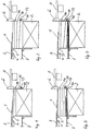
- Figures 1 to 4 show roughly schematically in Side view of a device according to the invention and the procedure for changing the stack.
- Fig. 5 shows an enlarged view Longitudinal section in the direction of suction through the bulletin board with the vibrating device.
- FIG. 6 shows a section along the line A - B of Fig. 5.
- FIGS. 1 to 4 The schematically shown in Figures 1 to 4 Stacking device is used for storing continuously transported in a stream of shed Cardboard sheets 1 on a stack 2 in the connection to a cross cutting machine.
- the stack 2 is on a lifting and lowering storage platform educated; in this example a scissor lift table, placed on the pallets.
- the sheets 1 are from a belt conveyor 3rd fed to the stacking area, the outlet side Deflection rollers 4 as well as the ejection rollers 5 above the maximum stack height in the Storage rack are stored.
- transversely Message board extending across the working width 6, the vertically stationary in or against the direction of sheet travel adjustable to different format lengths is. Its structure is shown in more detail in FIGS. 5 and 6 shown.
- the bulletin board 6 extends vertically Direction from an area above the feed level to below the bar grate 7. In his lower part in the area of the rods 8 vertical recesses so that the tips of the Bars 8 - as indicated in Fig. 6 - by Message board 6 can be moved through, for. B. when filing short formats.
- Prefers is the notice board 6 over the working width in separate separate segments, so two or more stack 2 with different format lengths can be formed side by side at the same time can.
- the bulletin board 6 or its individual Segments are at the end of adjustment rods 9 attached, which is approximately at the level of the belt conveyor 4 in and slidable against the direction of sheet travel in the stacker frame are stored. It can be in a horizontal Vibration in and against the direction of sheet travel be transferred.
- the front part 10 of the Message boards 6 is on the sheet stop side low friction, e.g. B. coated with PTFE.
- the Damper elements 12 are arranged at two heights: On the one hand on the suspension on part 11, on the other hand approx. 100 mm lower, i.e. in the area between the suspension and the point of attack the vibrating device 13.
- the sheet longitudinal edges are not shown vertical side guide plates, those on both sides of the machine and each between the stacks 2 in the direction of sheet travel extend.
- a sensor 14 is located slightly below the feed level, the second sensor 15 approx. 40 mm above the bar grate 7.
- Fig. 1 the storage on the stack 2nd shown, which is formed on a pallet. Of the Bar grate 7 is located outside the stacking area in a waiting position. During the arches 1 are continuously fed, the storage platform continuously lowered to the head the sheets 1 towards the stack 2 constantly hold. Controlling the height of the top of the stack takes place by means of the sensor 14. When the stack 2 has reached the desired size, e.g. Legs certain number of sheets 1 has been deposited, the batch change is initiated. This will be done first the stack 2 up at high speed lowered to sensor 15, then the lowering movement slows down until the top edge of the stack approx. 50 mm below the rods 8 of the Bar grate 7 is located (Fig. 2).
- the sheets will be 1 continue to be funded continuously, with by quickly lowering the stack 2 the Fan the rear edges of the supplied sheets 1, so that the rod grate 7 retract between them can.
- the retraction of the bar grate 7 is triggered as soon as the top of the stack is up located under it.
- there is a shaking motion of the front part 10 of the bulletin board 6 triggered by the eccentric elements of the vibrating device 13 is rotated.
- the shaking motion will be on the bar grate 7 forming partial stacks in a horizontal vibration offset in and against the direction of sheet travel. It has been shown that there is a suitable vibration sets when hard damper elements 12 in the heights specified above be and the eccentric 14 with a frequency from 60 - 70 Hz.
- the bar grate 7 in a first step with a Speed from approx. 120 mm / s to approx. 50% - 75% of the format length moved into the stacking area (Fig. 3). Meanwhile, the trailing edges of the sheets supplied below 1 placed on it. By shaking the one on it formed sub-stack, the friction is reduced, so that the bar grate 7 without compression or Damage to the sheets 1 can be retracted. After The rod grate becomes the continuous running-in phase 7 moved in cycles, the standstill and Travel cycles are set depending on the format. It has been shown that by the cyclical movement the rod grate 7 this easily between the leading edges of the sheet growing on it Partial stack 9 can be moved.
- the bar grate 7 is then opened moved back the stacking area so that the Part of the pallet is transferred. Once the Stack 2 reaches the height of the upper sensor 15 the storage platform will be accordingly the increase in height of the stack 2 continuously lowered. The stack 2 has the desired size reached, a stack change to the performed as described above.
Landscapes
- Engineering & Computer Science (AREA)
- Mechanical Engineering (AREA)
- Pile Receivers (AREA)
- Forming Counted Batches (AREA)
Claims (7)
- Procédé pour empiler des feuilles arrivant en nappe étalée (1), en particulier des feuilles de carton, sur une plate-forme de dépôt relevable et abaissable, dans leuquel, pendant un changement de pile, on opère un empilage intermédiaire sur une grille à barreaux (7) verticalement fixe et pouvant pénétrer horizontalement dans la zone de la pile dans la direction de circulation des feuilles, caractérisé en ce que, pour le changement d'une pile (2) pendant que des feuilles (1) sont amenées en continu, la pile (2) est d'abord abaissée jusqu'à ce que son arête supérieure se trouve à une faible distance sous la grille à barreaux (7) sous la grille à barreaux (7), l'abaissement est effectué si rapidement que les bords arrière des feuilles (1) arrivant sont écartés, de sorte que la grille à barreaux (7) peut être insérée dans la pile, et ensuite la grille à barreaux (7) est déplacée dans la zone de la pile, pendant que la pile partielle se format sur celle-ci est déplacée en une oscillation horizontale dans et contre la direction de circulation des feuilles.
- Procédé suivant la revendication 1, caractérisé en ce que pour produire l'oscillation horizontale, une planche de burée des feuilles (6) pour les arêtes antérieures des feuilles, disposée à l'extrémité de la pile (2), est mise en vibration.
- Pocédé suivant la revendication 2, caractérisé en ce que la grille à barreaux (7) entre par à coups au moins dans la dernière partie de son trajet de pénétration.
- Procédé suivant l'une quelconque des revendications 1 à 3, caractérisé en ce que, vers la fin de l'opération de pénétration, la pile (2) est légèrement relevée par le bas, afin de pousser vers le haut, devant la planche de butée (6), les arêtes antérieures des feuilles (1) qui pendent vers le bas.
- Dispositif pour la mise en oeuvre du procédé suivant l'une quelconque des revendications 1 à 4, pour empiler des feuilles amenées en nappe étalée (1) avec une plate-forme de dépôt relevable et abaissable sur laquelle se forme la pile (2), avec une grille à barreaux (7) verticalement fixe et pouvant pénétrer horizontalement dans la zone de la pile dans la direction de circulation des feuilles et avec une planche de butée des feuilles (6) disposée à l'extrémité de la zone de la pile pour les arêtes antérieures des feuilles, qui s'étend en direction verticale au moins depuis le plan d'amenée jusque sous la grille à barreaux (7), et avec un dispositif de vibration (13) destiné à déplacer la planche de butée (6) en une oscillation horizontale dans et contre la direction de circulation des feuilles, caractérisé en ce que la planche de butée (6) présente une partie antérieure (10), contre laquelle viennent buter les arêtes antérieures des feuilles, qui est fixée à une partie postérieure (11) par des éléments d'amortissement élastiques (12), le dispositif de vibration (13) agissant sur la partie antérieure (10).
- Dispositif suivant la revendication 5, caractérisé en ce que la partie antérieure (10) est fixée, en suspension vers le bas, à la partie postérieure (11) de la planche de butée (6) par des éléments d'amortissement élastiques (12), en ce que le dispositif de vibration (13) agit sur sa partie inférieure au-dessus de la grille à barreaux (7) et en ce que des éléments d'amortissement supplémentaires (12) sont disposés dans la zone située entre la suspension et le dispositif de vibration (13).
- Dispositif suivant l'une quelconque des revendications 5 ou 6, caractérisé en ce que la planche de butée (6) est revêtue sur le côté de butée des feuilles pour avoir un frottement faible.
Applications Claiming Priority (2)
| Application Number | Priority Date | Filing Date | Title |
|---|---|---|---|
| DE4221660A DE4221660C2 (de) | 1992-07-02 | 1992-07-02 | Verfahren und Vorrichtung zum Stapeln von Bogen |
| DE4221660 | 1992-07-02 |
Publications (3)
| Publication Number | Publication Date |
|---|---|
| EP0576820A1 EP0576820A1 (fr) | 1994-01-05 |
| EP0576820B1 EP0576820B1 (fr) | 1995-08-30 |
| EP0576820B2 true EP0576820B2 (fr) | 1998-09-02 |
Family
ID=6462279
Family Applications (1)
| Application Number | Title | Priority Date | Filing Date |
|---|---|---|---|
| EP93107985A Expired - Lifetime EP0576820B2 (fr) | 1992-07-02 | 1993-05-17 | Procédé et dispositif pour empiler des feuilles |
Country Status (6)
| Country | Link |
|---|---|
| US (1) | US5368288A (fr) |
| EP (1) | EP0576820B2 (fr) |
| JP (1) | JPH06156858A (fr) |
| DE (2) | DE4221660C2 (fr) |
| ES (1) | ES2079226T5 (fr) |
| FI (1) | FI933035A7 (fr) |
Families Citing this family (17)
| Publication number | Priority date | Publication date | Assignee | Title |
|---|---|---|---|---|
| DE19627241C2 (de) * | 1995-11-30 | 2002-03-07 | Heidelberger Druckmasch Ag | Vorrichtung zur Bildung eines Bogenstapels im Ausleger einer Bogendruckmaschine |
| GB2307679B (en) * | 1995-11-30 | 1999-10-06 | Heidelberger Druckmasch Ag | Apparatus for forming a sheet pile e.g. in a delivery of a sheet-fed printing machine |
| EP0790206B1 (fr) * | 1996-02-14 | 2001-04-25 | MAN Roland Druckmaschinen AG | Procédé et dispositif de changement automatique de piles |
| DE19708125A1 (de) * | 1997-02-28 | 1998-09-03 | Bielomatik Leuze & Co | Stapler |
| US5970833A (en) * | 1997-07-17 | 1999-10-26 | Elsner Engineering Works, Inc. | Stacking machine and method |
| BR0002821A (pt) * | 2000-05-11 | 2001-12-04 | Net 2 Net Empresa Paulista De | Sistema de interconexão de usuários à redemundial de computadores, internet, sem uso delinhas telefônicas tradicionais ou cabos coaxiaisde televisão a cabo |
| US6688083B1 (en) * | 2000-11-17 | 2004-02-10 | Lockheed Martin Corporation | Drop control mechanism for flat articles |
| DE10161891B4 (de) * | 2001-01-19 | 2017-09-14 | Heidelberger Druckmaschinen Ag | Verfahren zur Regelung bogenförmiges Material führender Elemente |
| AUPR292501A0 (en) * | 2001-02-07 | 2001-03-01 | Silverbrook Research Pty. Ltd. | A method and apparatus (ART100) |
| DE10134425A1 (de) * | 2001-07-19 | 2003-02-06 | Jagenberg Querschneider Gmbh | Vorrichtung zum Stapeln von Bögen, insbesondere von geschuppt zugeförderten Papier- oder Kartonbögen auf Paletten |
| DE10318573A1 (de) * | 2002-05-27 | 2003-12-11 | Heidelberger Druckmasch Ag | Vorrichtung zum seitenkantengleichen Stapeln von blattförmigen Bedruckstoffen |
| JP4448121B2 (ja) * | 2006-10-31 | 2010-04-07 | キヤノン株式会社 | シート積載装置及び画像形成装置 |
| DE102008054815A1 (de) | 2008-12-17 | 2010-07-01 | Koenig & Bauer Aktiengesellschaft | Vorrichtung zum Ausrichten von Bogen im Ausleger einer Bogen verarbeitenden Maschine |
| JP5669920B1 (ja) * | 2013-11-13 | 2015-02-18 | 三菱重工印刷紙工機械株式会社 | スケアリング装置及びカウンタエゼクタ並びに製函機 |
| US9896295B2 (en) * | 2014-11-25 | 2018-02-20 | A.G. Stacker Inc. | Buffer, stacking system including the buffer, and method of buffering |
| US10329114B2 (en) | 2015-11-17 | 2019-06-25 | A. G. Stacker Inc. | Stacker hopper with feed interrupt |
| US10843889B2 (en) | 2015-11-17 | 2020-11-24 | A.G. Stacker Inc. | Stacker hopper with feed interrupt |
Family Cites Families (11)
| Publication number | Priority date | Publication date | Assignee | Title |
|---|---|---|---|---|
| US2733064A (en) * | 1956-01-31 | martin | ||
| US2274713A (en) * | 1940-12-14 | 1942-03-03 | Fred M Brackett | Post for jogging machines |
| US2624577A (en) * | 1950-09-07 | 1953-01-06 | William R Peugnet | Paper jogging machine |
| DE2942965A1 (de) * | 1979-10-24 | 1981-05-07 | Automation für grafische Technik AG, 4005 Meerbusch | Stapeleinrichtung insbesondere fuer druckmaschinen |
| DE8527621U1 (de) * | 1985-09-27 | 1985-11-21 | Jagenberg AG, 4000 Düsseldorf | Bogenableger |
| DE3721393A1 (de) * | 1987-06-29 | 1989-01-12 | Heinz Dipl Ing Hohenschutz | Vorrichtungen fuer bogenablagen insbesondere an querschneidern in der papier- und kartonindustrie |
| DE8804066U1 (de) * | 1988-03-25 | 1988-05-11 | Jagenberg AG, 4000 Düsseldorf | Schütteleinrichtung für Bogenabstapelvorrichtung |
| DE3823806A1 (de) * | 1988-07-14 | 1990-01-18 | Jagenberg Ag | Vorrichtung zum abstapeln von boegen, insbesondere von kartonboegen |
| DE8903802U1 (de) * | 1989-03-28 | 1989-06-08 | Heidelberger Druckmaschinen Ag, 6900 Heidelberg | Bogenausleger an Rotationsdruckmaschinen |
| DE3923475A1 (de) * | 1989-07-15 | 1991-01-24 | Koenig & Bauer Ag | Bogenausleger fuer druckmaschinen |
| US5014974A (en) * | 1990-01-16 | 1991-05-14 | Numerical Concepts, Inc. | In-line, continuous paper batching system |
-
1992
- 1992-07-02 DE DE4221660A patent/DE4221660C2/de not_active Expired - Fee Related
-
1993
- 1993-05-17 DE DE59300527T patent/DE59300527D1/de not_active Expired - Fee Related
- 1993-05-17 ES ES93107985T patent/ES2079226T5/es not_active Expired - Lifetime
- 1993-05-17 EP EP93107985A patent/EP0576820B2/fr not_active Expired - Lifetime
- 1993-07-01 FI FI933035A patent/FI933035A7/fi unknown
- 1993-07-01 JP JP5163479A patent/JPH06156858A/ja active Pending
- 1993-07-02 US US08/087,613 patent/US5368288A/en not_active Expired - Fee Related
Also Published As
| Publication number | Publication date |
|---|---|
| DE4221660C2 (de) | 1994-10-13 |
| FI933035A0 (fi) | 1993-07-01 |
| US5368288A (en) | 1994-11-29 |
| ES2079226T3 (es) | 1996-01-01 |
| EP0576820B1 (fr) | 1995-08-30 |
| DE4221660A1 (de) | 1994-01-05 |
| JPH06156858A (ja) | 1994-06-03 |
| EP0576820A1 (fr) | 1994-01-05 |
| FI933035L (fi) | 1994-01-03 |
| ES2079226T5 (es) | 1999-01-16 |
| DE59300527D1 (de) | 1995-10-05 |
| FI933035A7 (fi) | 1994-01-03 |
Similar Documents
| Publication | Publication Date | Title |
|---|---|---|
| EP0576820B2 (fr) | Procédé et dispositif pour empiler des feuilles | |
| EP0187344B1 (fr) | Procédé et dispositif pour produire des piles individuelles composées d'une bande en accordéon | |
| EP0535360B1 (fr) | Sortie de feuilles | |
| EP0350642B1 (fr) | Dispositif pour empiler des feuilles, notamment des feuilles en carton | |
| EP0288814B1 (fr) | Dispositif pour subdiviser une bande de papier sans fin avec un plissement en accordéon | |
| EP0718231A2 (fr) | Dispositif pour empiler des feuilles, en particulier pour des feuilles en papier ou carton qui sont alimentées en se chevauchant | |
| EP0768261A1 (fr) | Dispositif et méthode pour plier et empiler en continu des produits en bande | |
| EP0392139A2 (fr) | Dispositif pour déposer des liasses de feuilles, en particulier des feuilles en papier, sur une pile | |
| EP2505536B1 (fr) | Dispositif de formation de piles | |
| EP0968128B1 (fr) | Dispositif d'empilage de feuilles, en particulier de feuilles de papier ou de carton transportees sur des palettes par un systeme a lamelles | |
| DE102010053587A1 (de) | Non-Stop-Stab mit Transportband | |
| DE3219693A1 (de) | Vorrichtung zur bildung von verarbeitungsfaehigen teilstapeln aus folienbogen, insbesondere papierbogen | |
| DE3220917C2 (de) | Verfahren zum Abteilen von Teilstapeln von einem Gesamtstapel und zum Ablegen jedes Teilstapels in schuppenförmiger Lage | |
| DE4231891A1 (de) | Verfahren zum automatischen Aufstapeln von Bögen sowie Bogenstapeleinrichtung | |
| DE2751605C2 (de) | Einrichtung zum Stapeln von Brettern o.dgl. | |
| EP0845431A2 (fr) | Procédé et dispositif d'empilage continu pour une machine à imprimer des feuilles | |
| EP1117609B2 (fr) | Dispositif permettant d'empiler des feuilles | |
| EP1264794B1 (fr) | Méthode et dispositif pour la formation d'une pile sur un récepteur de pile | |
| EP1412269B1 (fr) | Dispositif d'empilage de feuilles, en particulier de feuilles de papier ou de carton, transportees par margeur a nappe, sur des palettes | |
| DE1786380A1 (de) | Blatt-Stapelvorrichtung | |
| DE2224981B2 (de) | Schuppenauslage für Papierverarbeitungsmaschinen, insbesondere Falzmaschinen | |
| DE3422635C2 (fr) | ||
| DE1951887C (de) | Vorrichtung zum Überfuhren von Pa pierlagen von einem Bogenstapel auf einen Rütteltisch | |
| DE2115652A1 (de) | Verfahren und Vorrichtung zum Materialzuführen an eine bogenbe- oder bogenverarbeitende Maschine | |
| CH715498B1 (de) | Vorrichtung und Verfahren zur positionsgenauen Ablage von mindestens einer Signatur. |
Legal Events
| Date | Code | Title | Description |
|---|---|---|---|
| PUAI | Public reference made under article 153(3) epc to a published international application that has entered the european phase |
Free format text: ORIGINAL CODE: 0009012 |
|
| AK | Designated contracting states |
Kind code of ref document: A1 Designated state(s): DE ES GB IT |
|
| 17P | Request for examination filed |
Effective date: 19940513 |
|
| 17Q | First examination report despatched |
Effective date: 19940614 |
|
| GRAA | (expected) grant |
Free format text: ORIGINAL CODE: 0009210 |
|
| AK | Designated contracting states |
Kind code of ref document: B1 Designated state(s): DE ES GB IT |
|
| ITF | It: translation for a ep patent filed | ||
| GBT | Gb: translation of ep patent filed (gb section 77(6)(a)/1977) |
Effective date: 19950829 |
|
| REF | Corresponds to: |
Ref document number: 59300527 Country of ref document: DE Date of ref document: 19951005 |
|
| REG | Reference to a national code |
Ref country code: ES Ref legal event code: FG2A Ref document number: 2079226 Country of ref document: ES Kind code of ref document: T3 |
|
| PLAV | Examination of admissibility of opposition |
Free format text: ORIGINAL CODE: EPIDOS OPEX |
|
| PLBQ | Unpublished change to opponent data |
Free format text: ORIGINAL CODE: EPIDOS OPPO |
|
| PLBI | Opposition filed |
Free format text: ORIGINAL CODE: 0009260 |
|
| 26 | Opposition filed |
Opponent name: E.C.H. WILL GMBH Effective date: 19960523 |
|
| PLAV | Examination of admissibility of opposition |
Free format text: ORIGINAL CODE: EPIDOS OPEX |
|
| PLBF | Reply of patent proprietor to notice(s) of opposition |
Free format text: ORIGINAL CODE: EPIDOS OBSO |
|
| PLBF | Reply of patent proprietor to notice(s) of opposition |
Free format text: ORIGINAL CODE: EPIDOS OBSO |
|
| PLAW | Interlocutory decision in opposition |
Free format text: ORIGINAL CODE: EPIDOS IDOP |
|
| PGFP | Annual fee paid to national office [announced via postgrant information from national office to epo] |
Ref country code: DE Payment date: 19980420 Year of fee payment: 6 |
|
| PLAW | Interlocutory decision in opposition |
Free format text: ORIGINAL CODE: EPIDOS IDOP |
|
| PGFP | Annual fee paid to national office [announced via postgrant information from national office to epo] |
Ref country code: GB Payment date: 19980624 Year of fee payment: 6 |
|
| PGFP | Annual fee paid to national office [announced via postgrant information from national office to epo] |
Ref country code: ES Payment date: 19980629 Year of fee payment: 6 |
|
| PUAH | Patent maintained in amended form |
Free format text: ORIGINAL CODE: 0009272 |
|
| 27A | Patent maintained in amended form |
Effective date: 19980902 |
|
| AK | Designated contracting states |
Kind code of ref document: B2 Designated state(s): DE ES GB IT |
|
| GBTA | Gb: translation of amended ep patent filed (gb section 77(6)(b)/1977) | ||
| REG | Reference to a national code |
Ref country code: ES Ref legal event code: DC2A Kind code of ref document: T5 Effective date: 19981127 |
|
| PG25 | Lapsed in a contracting state [announced via postgrant information from national office to epo] |
Ref country code: GB Free format text: LAPSE BECAUSE OF NON-PAYMENT OF DUE FEES Effective date: 19990517 |
|
| PG25 | Lapsed in a contracting state [announced via postgrant information from national office to epo] |
Ref country code: ES Free format text: LAPSE BECAUSE OF NON-PAYMENT OF DUE FEES Effective date: 19990518 |
|
| GBPC | Gb: european patent ceased through non-payment of renewal fee |
Effective date: 19990517 |
|
| PG25 | Lapsed in a contracting state [announced via postgrant information from national office to epo] |
Ref country code: DE Free format text: LAPSE BECAUSE OF NON-PAYMENT OF DUE FEES Effective date: 20000301 |
|
| REG | Reference to a national code |
Ref country code: ES Ref legal event code: FD2A Effective date: 20010503 |
|
| PG25 | Lapsed in a contracting state [announced via postgrant information from national office to epo] |
Ref country code: IT Free format text: LAPSE BECAUSE OF NON-PAYMENT OF DUE FEES;WARNING: LAPSES OF ITALIAN PATENTS WITH EFFECTIVE DATE BEFORE 2007 MAY HAVE OCCURRED AT ANY TIME BEFORE 2007. THE CORRECT EFFECTIVE DATE MAY BE DIFFERENT FROM THE ONE RECORDED. Effective date: 20050517 |