EP0576875B1 - Lärmschutzwand - Google Patents
Lärmschutzwand Download PDFInfo
- Publication number
- EP0576875B1 EP0576875B1 EP93109162A EP93109162A EP0576875B1 EP 0576875 B1 EP0576875 B1 EP 0576875B1 EP 93109162 A EP93109162 A EP 93109162A EP 93109162 A EP93109162 A EP 93109162A EP 0576875 B1 EP0576875 B1 EP 0576875B1
- Authority
- EP
- European Patent Office
- Prior art keywords
- watering
- cassette
- magazine
- noise protection
- noise
- Prior art date
- Legal status (The legal status is an assumption and is not a legal conclusion. Google has not performed a legal analysis and makes no representation as to the accuracy of the status listed.)
- Expired - Lifetime
Links
- 239000004568 cement Substances 0.000 claims abstract description 17
- 235000015097 nutrients Nutrition 0.000 claims abstract description 7
- 241000196324 Embryophyta Species 0.000 claims abstract 2
- 230000001681 protective effect Effects 0.000 claims 2
- 230000004888 barrier function Effects 0.000 description 19
- 239000000835 fiber Substances 0.000 description 14
- 238000009413 insulation Methods 0.000 description 14
- XLYOFNOQVPJJNP-UHFFFAOYSA-N water Substances O XLYOFNOQVPJJNP-UHFFFAOYSA-N 0.000 description 7
- 238000013461 design Methods 0.000 description 2
- 238000009434 installation Methods 0.000 description 2
- 239000000463 material Substances 0.000 description 2
- 239000002557 mineral fiber Substances 0.000 description 2
- 238000010998 test method Methods 0.000 description 2
- 238000012360 testing method Methods 0.000 description 2
- 230000000007 visual effect Effects 0.000 description 2
- 229910000831 Steel Inorganic materials 0.000 description 1
- 229910000746 Structural steel Inorganic materials 0.000 description 1
- 238000010521 absorption reaction Methods 0.000 description 1
- 230000002238 attenuated effect Effects 0.000 description 1
- 210000003403 autonomic nervous system Anatomy 0.000 description 1
- 239000004566 building material Substances 0.000 description 1
- 239000004927 clay Substances 0.000 description 1
- 238000004891 communication Methods 0.000 description 1
- 238000011161 development Methods 0.000 description 1
- 230000018109 developmental process Effects 0.000 description 1
- 201000010099 disease Diseases 0.000 description 1
- 208000037265 diseases, disorders, signs and symptoms Diseases 0.000 description 1
- 230000000694 effects Effects 0.000 description 1
- 230000007613 environmental effect Effects 0.000 description 1
- 239000003344 environmental pollutant Substances 0.000 description 1
- 230000005284 excitation Effects 0.000 description 1
- 239000011094 fiberboard Substances 0.000 description 1
- 230000001771 impaired effect Effects 0.000 description 1
- 230000002262 irrigation Effects 0.000 description 1
- 238000003973 irrigation Methods 0.000 description 1
- 238000005259 measurement Methods 0.000 description 1
- 239000002184 metal Substances 0.000 description 1
- 239000011490 mineral wool Substances 0.000 description 1
- 231100000719 pollutant Toxicity 0.000 description 1
- 239000011148 porous material Substances 0.000 description 1
- 230000000717 retained effect Effects 0.000 description 1
- 239000010959 steel Substances 0.000 description 1
- 238000005406 washing Methods 0.000 description 1
Images

Classifications
-
- E—FIXED CONSTRUCTIONS
- E01—CONSTRUCTION OF ROADS, RAILWAYS, OR BRIDGES
- E01F—ADDITIONAL WORK, SUCH AS EQUIPPING ROADS OR THE CONSTRUCTION OF PLATFORMS, HELICOPTER LANDING STAGES, SIGNS, SNOW FENCES, OR THE LIKE
- E01F8/00—Arrangements for absorbing or reflecting air-transmitted noise from road or railway traffic
- E01F8/02—Arrangements for absorbing or reflecting air-transmitted noise from road or railway traffic specially adapted for sustaining vegetation or for accommodating plants ; Embankment-type or crib-type noise barriers; Retaining walls specially adapted to absorb or reflect noise
- E01F8/027—Arrangements for absorbing or reflecting air-transmitted noise from road or railway traffic specially adapted for sustaining vegetation or for accommodating plants ; Embankment-type or crib-type noise barriers; Retaining walls specially adapted to absorb or reflect noise with external support, e.g. wall facing
Definitions
- the invention relates to a noise barrier according to the preamble of claim 1.
- Noise barriers are erected on traffic routes in order to protect adjacent residential areas from the noise emanating from the traffic route.
- noise barriers consist of steel, galvanized posts with interposed, interchangeable wall elements. Depending on the building material and wall system, certain frequencies are more or less attenuated. Elements that mainly reflect the sound have a small wall cross section and exist for example made of concrete, metal or plastic profiles. In contrast, elements that absorb sound for the most part are made wider and consist of a porous material, for example an open-pored expanded clay, facing concrete or rock wool. The sound penetrates the open-pored materials and is converted into heat.
- a noise barrier known from DE-OS 38 12 394, which consists of a framework for holding and receiving wall parts, the wall parts consisting of planted cassettes which are stacked to form the wall height.
- Such a noise barrier does not disturb the landscape, but offers an aesthetically successful sight. It offers a biotope for many small creatures and ensures that pollutants are removed and good heat absorption.
- a noise protection wall constructed in accordance with DE-OS 38 12 394 sufficiently fulfills the 'Technical regulations and guidelines for the implementation of noise protection walls on streets' (ZTV-Lsw 88), which prescribe a reduction of the A-weighted sound insulation value by at least 25 dB .
- a particular disadvantage is that in the case of noise barriers constructed according to DE-OS 38 12 394, vertical pipes for load distribution had to be installed subsequently in order to increase the stability of the noise barrier to the value required in ZTV-Lsw 88.
- a sound-absorbing wall can be taken from cassettes, a plate extending over the entire vertical surface of the cassette being arranged in the center of each cassette.
- the plate has soundproofing properties. None is said about the material of the plate.
- Each element comprises on its lower side a trough for storing water and an overflow that supplies the element below with water.
- the lower elements are only supplied with water if there is an excess of water in the troughs that flows off via the overflow.
- the invention has for its object to improve a noise barrier of the type mentioned in such a way that its sound insulation and stability is increased with about the same installation and cost, without reducing the green, pollutant-reducing area and ensuring the water supply to the green area.
- the airborne sound insulation is approximately 31 to 36 dB, so that the technical regulation that 25 dB is required, more than is fulfilled.
- a noise barrier of the type mentioned at the outset means that the noise is felt only about half as loud.
- the low and medium frequencies, which are perceived as very disturbing, are particularly insulated.
- the fiber cement panel arranged in the middle does not disturb the visual impression in any way and does not reduce the green area.
- the installation of a fiber cement board is neither complex nor cost-intensive.
- the intrinsic stability of the cassettes is significantly improved with the fiber cement board. It is therefore not necessary to install additional scaffolding elements.
- the fiber cement board is at least 8 mm thick.
- the mass achieved thereby shifts the natural resonance of the fiber cement board into a deep, non-critical frequency range, so that no excitation in the natural resonance can take place due to the disturbing sound frequencies.
- a watering mat is arranged in each case in the horizontal edge zones of a cassette on both sides of the fiber cement board.
- the watering mat can be on horizontal edge of the cassette can be arranged in one piece or a one-piece watering mat can be arranged between two cassettes.
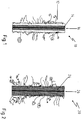
- 1 and 2 each show a cassette 10 and 20 of a noise barrier according to the invention.
- the cassette 20 shown in FIG. 2 differs from that shown in FIG. 1 in that it has an 8 mm thick fiber cement plate 26 as a nutrient medium on both sides no vegetation mat, but only a mineral fiber insulation board 24, which is greened directly.
- the inherent stability of the cassette 10, 20 is significantly increased by the fiber cement plate 26, so that otherwise usual frame elements for stiffening the cassette can be omitted in practice.
- FIG. 3 shows in an enlarged detail from FIG. 1 the lower end region of the cassette 10.
- a one-piece watering mat 30 is arranged on the lower horizontal edge of the cassette 10. This has the effect that the water supplied via drip irrigation at the upper end of the noise barrier is retained in the cassettes and is dispensed to the plants in even doses on both sides of the fiber cement board.
- washing mat 32 in two parts and to arrange it on both sides of the fiber insulation board 16 in the edge region of the cassette.
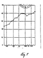
- FIG. 5 shows a graphical representation of the measured values of the noise insulation test of the cassette, which was carried out as part of the test procedure in accordance with ZTV-Lsw 88.
- the test procedure is called DIN 52 210-03-M-L-P-W.
- the frequency f is shown on the abscissa, while the sound insulation index R is entered on the ordinate.
- the sound insulation measured for the noise barrier according to the invention is between 34 and 39 dB. The particularly good insulation properties in the medium and low frequency range can be seen.
Landscapes
- Engineering & Computer Science (AREA)
- Architecture (AREA)
- Civil Engineering (AREA)
- Structural Engineering (AREA)
- Devices Affording Protection Of Roads Or Walls For Sound Insulation (AREA)
- Cultivation Receptacles Or Flower-Pots, Or Pots For Seedlings (AREA)
- Materials For Medical Uses (AREA)
- Laminated Bodies (AREA)
- Building Environments (AREA)
Description
- Die Erfindung betrifft eine Lärmschutzwand nach dem Oberbegriff des Anspruches 1.
- Lärmschutzwände werden an Verkehrswegen errichtet, um anliegende Wohngebiete vor dem vom Verkehrsweg ausgehenden Lärm zu schützen.
- Die meisten Lärmschutzwände bestehen aus stählernen, verzinkten Pfosten mit zwischengesetzten, austauschbaren Wandelementen. Je nach Baustoff und Wandsystem werden bestimmte Frequenzen mehr oder weniger stark gedämpft. Elemente, die den Schall überwiegend reflektieren, haben einen geringen Wandquerschnitt und bestehen beispielsweise aus Beton, Metall-oder Kunststoffprofilen. Demgegenüber sind Elemente, die den Schall größtenteils absorbieren breiter ausgebildet und bestehen aus einem porigen Material, beispielsweise aus einem offenporigen Blähton, Vorsatzbeton oder Steinwolle. Dabei dringt der Schall in die offenporigen Stoffe ein und wird in Wärme umgesetzt.
- Eine ästhetische Gestaltung dieser Elemente ist schwierig. Zumeist sind sie auffällig strukturiert und bunt angestrichen. Diese Ausgestaltung stört das Landschaftsbild und der Anteil der Bürger, die sich gegen Lärmschutzwände aussprechen, weil diese ihren visuellen Bedürfnissen nicht gerecht werden, nimmt zu.
- Ein nachträgliche Bepflanzung, die die Lärmschutzwände verdecken könnte, ist oft aus Platzgründen nicht möglich oder zu kostenintensiv.
- Einen Lösungsweg zeigt eine aus der DE-OS 38 12 394 bekannte Lärmschutzwand auf, die aus einem Gerüst zur Halterung und Aufnahme von Wandteilen besteht, wobei die Wandteile aus bepflanzten Cassetten bestehen, die zur Bildung der Wandhöhe übereinandergestapelt sind. Eine solche Lärmschutzwand stört das Landschaftsbild nicht, sondern bietet einen ästhetisch gelungenen Anblick. Sie bietet ein Biotop für viele Kleinlebewesen und sorgt für eine Schadstoffabfuhr und gute Wärmeabsorption.
- Bezüglich der Schalldämmungswerte erfüllt eine gemäß der DE-OS 38 12 394 errichtete Lärmschutzwand hinreichend die 'Technischen Vorschriften und Richtlinien für die Ausführung von Lärmschutzwänden an Straßen' (ZTV-Lsw 88), die eine Reduzierung des A-bewerteten Schalldämmaßes um wenigstens 25 dB vorschreiben.
- In letzter Zeit hat sich das Verkehrsaufkommen auf den Straßen und in der Luft weiter erhöht, zahlreiche neue Gewerbegebiete mit zusätzlichen Lärmquellen sind geschaffen worden und viele Wohnsiedlungen, die gestern noch im Grünen lagen, liegen heute mitten in einer Industrieansiedlung oder in der Nähe einer verkehrsreichen Straße. Lärm führt zur Beeinträchtigung der akustischen Kommunikation, von Schlaf und Entspannung und Erkrankungen des vegetativen Nervensystems. Von daher ist es verständlich, wenn der Lärm, laut einer Umfrage, als eine der stärksten Umweltbelästigungen empfunden wird. Eine begrünte Lärmschutzwand, wie die aus der DE-OS 38 12 394, die nur hinreichend den Lärm dämmt, ist nicht mehr akzeptabel.
- Nachteilig ist insbesondere auch, daß bei nach der DE-OS 38 12 394 aufgebauten Lärmschutzwänden nachträglich senkrechte Rohre zur Lastverteilung eingebaut werden mußten, um die Standsicherheit der Lärmschutzwand auf den in den ZTV-Lsw 88 geforderten Wert zu erhöhen.
- Aus der NL-A-8 601 019 ist eine schallabwehrende Wand aus Kassetten entnehmbar, wobei in der Mitte jeder Kassette eine sich über die gesamte senkrechte Fläche der Kassette erstrekkende Platte angeordnet ist. Die Platte hat schalldämmende Eigenschaften. Uber das Material der Platte ist nichts ausgesagt.
- Zu beiden Seiten der Platte befinden sich Faserstoffplatten, die begrünt werden können.
- Jedes Element umfaßt an seiner unteren Seite einen Trog zur Speicherung von Wasser und einen Uberlauf, der das darunter liegende Element mit Wasser versorgt. Die jeweils unteren Elemente werden aber nur dann mit Wasser versorgt, wenn in den Trögen ein Wasserüberschuß herrscht, der über den Überlauf abfließt.
- Der Erfindung liegt die Aufgabe zugrunde eine Lärmschutzwand der eingangs genannten Art dahingehend zu verbessern, daß ihre Schalldämmung und Standsicherheit bei etwa gleichem Montage- und Kostenaufwand weiter erhöht wird, ohne die begrünte, schadstoffreduzierende Fläche zu verkleinern und die Wasserversorgung der begrünten Fläche zu gewährleisten.
- Diese Aufgabe wird bei einer Lärmschutzwand nach dem Oberbegriff des Anspruches 1 durch die im Kennzeichen genannten Merkmale gelöst.
- Durch die erfindungsgemäß in der Mitte einer jeden Cassette der Lärmschutzwand angeordnete und sich über die gesamte senkrechte Fläche der Cassette erstreckende Faserzementplatte beträgt die Luftschalldämmung, wie sich überraschenderweise aus amtlichen Messungen ergeben hat, ca. 31 bis 36 dB, so daß die technische Vorschrift, die 25 dB verlangt, mehr als erfüllt ist. Eine solche Verminderung des Lautstärkepegels um etwa 6 bis 10 dB gegenüber einer Lärmschutzwand der eingangs genannten Art bewirkt, daß der Lärm nur noch etwa halb so laut empfunden wird. Zusätzlich werden insbesondere die als sehr störend empfundenen tiefen und mittleren Frequenzen gedämmt. Die in der Mitte angeordnete Faserzementplatte stört in keinerlei Weise den optischen Eindruck und reduziert nicht die begrünte Fläche. Ferner ist der Einbau einer Faserzementplatte weder aufwendig, noch kostenintensiv. Gleichzeitig wird mit der Faserzementplatte auch die Eigenstabilität der Cassetten wesentlich verbessert. Auf den Einbau zusätzlicher Gerüstelemente kann daher verzichtet werden.
- In praktischer Ausgestaltung der Erfindung ist die Faserzementplatte mindestens 8 mm dick ausgebildet.
- Die dadurch erzielte Masse verlegt die Eigenresonanz der Faserzementplatte in einen tiefen unkritischen Frequenzbereich, so daß durch die störenden Schallfrequenzen keine Anregung in der Eigenresonanz stattfinden kann.
- Ferner ist nach der Erfindung vorgesehen, daß eine Wässerungsmatte jeweils in den waagerechten Randzonen einer Cassette beidseitig der Faserzementplatte angeordnet ist.
- Alternativ dazu kann die Wässerungsmatte jeweils am waagerechten Rand der Cassette einteilig angeordnet sein oder es kann eine einteilige Wässerungsmatte jeweils zwischen zwei Cassetten angeordnet sein.
- Hierdurch wird erreicht, daß stets das Nährmedium und die Pflanzen zu beiden Seiten der Faserzementplatte mit Wasser versorgt werden.
- Weiterbildungen und vorteilhafte Ausgestaltungen der Erfindung ergeben sich aus den Ansprüchen, der weiteren Beschreibung und der Zeichnung. In dieser zeigen:
- Fig. 1
- einen Querschnitt durch eine Cassette einer Lärmschutzwand in einer ersten Ausgestaltung,
- Fig. 2
- einen Querschnitt durch eine Cassette in einer zweiten Ausgestaltung,
- Fig. 3
- einen vergrößerten Ausschnitt aus Fig. 1,
- Fig. 4
- ein alternatives Ausführungsbeispiel zu Fig. 3 und
- Fig. 5
- eine graphische Darstellung der Meßwerte der Lärmdämmungsprüfung der Lärmschutzwand
- Fig. 1 und 2 zeigen jeweils eine Cassette 10 und 20 einer Lärmschutzwand nach der Erfindung.
- Die Cassette 10 besteht aus einem feuerverzinkten, zusätzlich kunststoffbeschichteten, gitterförmigen Grundgestell aus dünnem Baustahl, das der Übersichtlichkeit wegen nicht dargestellt ist. Hinter den in der Lärmschutzwand vertikal angeordneten Längswänden der Cassette befindet sich auf beiden Wandseiten als Nährmedium eine 19 mm dicke Vegetationsmatte 12, parallel dazu liegt jeweils eine 20 mm dicke mineralische Faserdämmstoffplatte (RG trocken = 120 kg/m3 ) 14. Zwischen den Faserdämmstoffplatten 14 ist in der Mitte der Cassette 10 eine 8 mm dicke Faserzementplatte 16 eingebaut. Entlang der beiden Außenwände der Cassette sind Höhere und Niedere Pflanzen vorkultiviert.
- Die in Fig. 2 abgebildete Cassette 20 unterscheidet sich von der in Fig. 1 abgebildeten dadurch, daß sie beidseitig einer 8 mm dicken Faserzementplatte 26 als Nährmedium keine Vegetationsmatte, sondern nur eine mineralische Faserdämmstoffplatte 24, die direkt begrünt ist, besitzt.
- Durch die Faserzementplatte 26 wird die Eigenstabilität der Cassette 10, 20 wesentlich erhöht, so daß in der Praxis sonst übliche Gerüstelemente zur Aussteifung der Cassette entfallen können.
- Fig. 3 zeigt in einem vergrößerten Ausschnitt aus Fig. 1 den unteren Endbereich der Cassette 10. Dabei ist am unteren waagerechten Rand der Cassette 10 eine einteilige Wässerungsmatte 30 angeordnet. Diese bewirkt, daß das über eine Tröpfchenbewässerung am oberen Ende der Lärmschutzwand zugeführte Wasser jeweils in den Cassetten zurückgehalten und gleichmäßig dosiert auf beiden Seiten der Faserzementplatte an die Pflanzen abgegeben wird.
- Es ist natürlich auch möglich, wie in Fig. 4 gezeigt, die Wässerungsmatte 32 zweiteilig auszubilden und beiderseits der Faserdämmplatte 16 im Randbereich der Cassette anzuordnen.
- Beide Cassetten 10 und 20 erfüllen den in der Vorschrift 'ZTV Lsw 88' des Bundesministers für Verkehr geforderten Schalldämmungswert von 25 dB mit Werten zwischen 31 und 36 dB weit über das erforderliche Maß hinaus.
- In Fig. 5 ist dazu eine graphische Darstellung der Meßwerte der Lärmdämmungsprüfung der Cassette abgebildet, die im Rahmen des Prüfungsverfahrens gemäß der ZTV-Lsw 88 durchgeführt worden ist. Das Prüfungsverfahren trägt die Bezeichnung DIN 52 210-03-M-L-P-W. Auf der Abszisse ist die Frequenz f dargestellt, während auf der Ordinaten das Schalldämmaß R eingetragen ist. Das bewertete Schalldämmaß liegt bei der erfindungsgemäßen Lärmschutzwand zwischen 34 und 39 dB. Es zeigen sich die besonders guten Dämmeigenschaften im mittleren und tiefen Frequenzbereich.
Claims (2)
- Lärmschutzwand mit einem Gerüst zur Halterung und Aufnahme von Wandteilen, wobei die Wandteile durch ein Nährmedium enthaltene Cassetten (10,20) gebildet sind, die zur Bildung der Wandhöhe übereinander angeordnet sind, wobei die Cassetten vorkultiviert und mit Niederen und/oder Höheren Pflanzen bewachsen sind und als komplette Baueinheit aus einem Trag- und Schutzgestell bestehen, in dem das Nährmedium angeordnet ist, und wobei oben auf der Lärmschutzwand eine Tröpfchenbewässerung vorgesehen ist und in der Mitte einer jeden Cassette eine über die gesamte senkrechte Fläche der Cassette sich erstreckende Platte angeordnet ist, dadurch gekennzeichnet, daß die Platte eine Faserzementplatte (16, 26) mit einer Mindestdicke von 8 mm ist, und daß Wässerungsmatten vorgesehen sind, die sowohl wasserspeichernde als auch wasserabgebende Eigenschaften besitzen, wobei eine Wässerungsmatte (32) jeweils in den waagerechten Randzonen einer Cassette (10, 20) beidseitig der Faserzementplatte (16, 26) oder eine einteilige Wässerungsmatte (30) jeweils am waagerechten Rand der Cassette (10, 20) oder eine einteilige Wässerungsmatte (30) jeweils zwischen zwei Cassetten (10, 20) angeordnet sind.
- Lärmschutzwand nach Anspruch 1, dadurch gekennzeichnet, daß bei Anordnung der Wässerungsmatten (32) jeweils in den waagerechten Randzonen einer Cassette (10, 20) beidseitig der Faserzementplatte (16, 26) oder jeweils zwischen zwei Cassetten (10, 20) die Faserzementplatte (16, 26) an waagerechten Bereichen des Trag- und Schutzgestells anliegt.
Applications Claiming Priority (2)
| Application Number | Priority Date | Filing Date | Title |
|---|---|---|---|
| US07/902,673 US5361537A (en) | 1992-06-23 | 1992-06-23 | Noise protection wall |
| US902673 | 1992-06-23 |
Publications (2)
| Publication Number | Publication Date |
|---|---|
| EP0576875A1 EP0576875A1 (de) | 1994-01-05 |
| EP0576875B1 true EP0576875B1 (de) | 1997-04-02 |
Family
ID=25416218
Family Applications (1)
| Application Number | Title | Priority Date | Filing Date |
|---|---|---|---|
| EP93109162A Expired - Lifetime EP0576875B1 (de) | 1992-06-23 | 1993-06-08 | Lärmschutzwand |
Country Status (5)
| Country | Link |
|---|---|
| US (1) | US5361537A (de) |
| EP (1) | EP0576875B1 (de) |
| AT (1) | ATE151134T1 (de) |
| DE (1) | DE59306010D1 (de) |
| ES (1) | ES2101168T3 (de) |
Families Citing this family (10)
| Publication number | Priority date | Publication date | Assignee | Title |
|---|---|---|---|---|
| WO1998000607A1 (en) * | 1996-06-28 | 1998-01-08 | Rockwool International A/S | A sound absorbing and/or reducing wall or baffle |
| DE19652636B4 (de) * | 1996-12-18 | 2005-02-24 | Thomas Rothfuss | Lärmschutzwand aus Drahtkörben |
| WO2005078211A1 (en) * | 2004-02-13 | 2005-08-25 | Elevated Landscape Technologies | Green roofing apparatus, system and method |
| US7627983B1 (en) | 2004-10-15 | 2009-12-08 | Deutsch-Aboulmahassine Elizabeth | Modular, wall-mounted plant growing system |
| US20070283653A1 (en) * | 2006-06-08 | 2007-12-13 | Gregory Garner | Green roofing system including dimpled anchor layer |
| IT1392808B1 (it) * | 2009-02-03 | 2012-03-23 | Perlite Italiana S R L | Elemento strutturale per paratie verticali inverdite di ambienti confinati interni ed esterni. |
| DE202009007311U1 (de) * | 2009-05-20 | 2010-09-23 | K. Schütte GmbH | Lärmschutzelement |
| US20110225883A1 (en) * | 2010-03-16 | 2011-09-22 | Cliffords Perennial And Vine Inc | Vegetation wall |
| ITBO20110325A1 (it) | 2011-06-06 | 2012-12-07 | Euroambiente S R L | Parete fonoassorbente inverdita |
| EP4331348B1 (de) * | 2022-09-02 | 2025-02-19 | Daniel S. Spiro | Modulares wandsystem und modulare wand |
Family Cites Families (5)
| Publication number | Priority date | Publication date | Assignee | Title |
|---|---|---|---|---|
| SU815195A1 (ru) * | 1978-10-05 | 1981-03-23 | Ленинградская Ордена Ленина Лесотех-Ническая Академия Им.C.M.Кирова | Звукопоглощающа облицовка |
| NL8601019A (nl) * | 1986-04-21 | 1987-11-16 | Hollandsche Betongroep Nv | Geluidwerende wand. |
| DE3812394A1 (de) * | 1988-04-14 | 1989-11-02 | Wolfgang Behrens | Laermschutzwand |
| IT8845517A0 (it) * | 1988-11-07 | 1988-11-07 | Menichini Luigi | Pannello modulare fonoassorbente e fonoisolante con faccia a griglia lamellare verso la fonte del rumore |
| NL8900665A (nl) * | 1989-03-17 | 1990-10-16 | Rockwool Grodan Bv | Met vegetatie begroeibare wand. |
-
1992
- 1992-06-23 US US07/902,673 patent/US5361537A/en not_active Expired - Fee Related
-
1993
- 1993-06-08 ES ES93109162T patent/ES2101168T3/es not_active Expired - Lifetime
- 1993-06-08 EP EP93109162A patent/EP0576875B1/de not_active Expired - Lifetime
- 1993-06-08 AT AT93109162T patent/ATE151134T1/de not_active IP Right Cessation
- 1993-06-08 DE DE59306010T patent/DE59306010D1/de not_active Expired - Fee Related
Also Published As
| Publication number | Publication date |
|---|---|
| ES2101168T3 (es) | 1997-07-01 |
| US5361537A (en) | 1994-11-08 |
| DE59306010D1 (de) | 1997-05-07 |
| ATE151134T1 (de) | 1997-04-15 |
| EP0576875A1 (de) | 1994-01-05 |
Similar Documents
| Publication | Publication Date | Title |
|---|---|---|
| EP0337085B1 (de) | Lärmschutzwand | |
| EP0576875B1 (de) | Lärmschutzwand | |
| DE2842325A1 (de) | Absorbereinheit und daraus hergestelltes laermschutzschild | |
| EP0417049B1 (de) | Plattenelement für eine Lärmschutzwand | |
| DE8111266U1 (de) | Isolierelement | |
| WO2010133203A1 (de) | Lärmschutzelement | |
| EP0943747B1 (de) | Verfahren und Vorrichtung zur Ableitung von Wasser von einer im wesentlichen ebenen Fläche | |
| EP0202346B1 (de) | Fertigelement mit Vegetation | |
| DE3426639C2 (de) | ||
| DE10255256B4 (de) | Lärmschutzeinrichtung | |
| DE3545112C2 (de) | Bepflanzbare Lärmschutzanlage | |
| CH600078A5 (en) | Traffic noise screening composite wall element | |
| DE3631257C2 (de) | Bauelement für Schallschutzwände | |
| DE29702425U1 (de) | Wärmedämmendes Dachbegrünungs-Element | |
| DE29616665U1 (de) | Balkon | |
| EP0654103A1 (de) | Verfahren zum herstellen einer lärmschutzwand und lärmschutzwand | |
| DE3102692A1 (de) | Teilabdeckung fuer eine strasse zum zwecke des laermschutzes | |
| DE29823461U1 (de) | Sichtschutzwand | |
| DE2538667A1 (de) | Schallabschirmwand aus schallschluckendem beton | |
| DE202019103793U1 (de) | Lärmschutzwand mit einer Vielzahl an ihr angeordneter Hohlkörperprofilen | |
| DE3436402A1 (de) | Element fuer die errichtung einer schallschutzwand | |
| DE7522101U (de) | Schallschutzzaun | |
| DE102009022235A1 (de) | Lärmschutzelement | |
| DE20110085U1 (de) | Halterung für einen Tür- oder Fensteraustritt eines Gebäudes | |
| DE19706367C2 (de) | Schallschutzwand |
Legal Events
| Date | Code | Title | Description |
|---|---|---|---|
| PUAI | Public reference made under article 153(3) epc to a published international application that has entered the european phase |
Free format text: ORIGINAL CODE: 0009012 |
|
| AK | Designated contracting states |
Kind code of ref document: A1 Designated state(s): AT BE CH DE ES FR GB IE IT LI LU MC NL |
|
| 17P | Request for examination filed |
Effective date: 19940318 |
|
| 17Q | First examination report despatched |
Effective date: 19950505 |
|
| GRAG | Despatch of communication of intention to grant |
Free format text: ORIGINAL CODE: EPIDOS AGRA |
|
| GRAH | Despatch of communication of intention to grant a patent |
Free format text: ORIGINAL CODE: EPIDOS IGRA |
|
| GRAH | Despatch of communication of intention to grant a patent |
Free format text: ORIGINAL CODE: EPIDOS IGRA |
|
| GRAA | (expected) grant |
Free format text: ORIGINAL CODE: 0009210 |
|
| AK | Designated contracting states |
Kind code of ref document: B1 Designated state(s): AT BE CH DE ES FR GB IE IT LI LU MC NL |
|
| REF | Corresponds to: |
Ref document number: 151134 Country of ref document: AT Date of ref document: 19970415 Kind code of ref document: T |
|
| REG | Reference to a national code |
Ref country code: CH Ref legal event code: EP |
|
| ITF | It: translation for a ep patent filed | ||
| REF | Corresponds to: |
Ref document number: 59306010 Country of ref document: DE Date of ref document: 19970507 |
|
| GBT | Gb: translation of ep patent filed (gb section 77(6)(a)/1977) |
Effective date: 19970422 |
|
| ET | Fr: translation filed | ||
| PG25 | Lapsed in a contracting state [announced via postgrant information from national office to epo] |
Ref country code: LU Free format text: LAPSE BECAUSE OF NON-PAYMENT OF DUE FEES Effective date: 19970608 Ref country code: IE Free format text: LAPSE BECAUSE OF NON-PAYMENT OF DUE FEES Effective date: 19970608 |
|
| REG | Reference to a national code |
Ref country code: ES Ref legal event code: FG2A Ref document number: 2101168 Country of ref document: ES Kind code of ref document: T3 |
|
| REG | Reference to a national code |
Ref country code: IE Ref legal event code: FG4D Free format text: 72989 |
|
| PG25 | Lapsed in a contracting state [announced via postgrant information from national office to epo] |
Ref country code: MC Effective date: 19971231 |
|
| PLBE | No opposition filed within time limit |
Free format text: ORIGINAL CODE: 0009261 |
|
| STAA | Information on the status of an ep patent application or granted ep patent |
Free format text: STATUS: NO OPPOSITION FILED WITHIN TIME LIMIT |
|
| 26N | No opposition filed | ||
| PGFP | Annual fee paid to national office [announced via postgrant information from national office to epo] |
Ref country code: GB Payment date: 19990426 Year of fee payment: 7 |
|
| PGFP | Annual fee paid to national office [announced via postgrant information from national office to epo] |
Ref country code: FR Payment date: 19990517 Year of fee payment: 7 |
|
| PGFP | Annual fee paid to national office [announced via postgrant information from national office to epo] |
Ref country code: CH Payment date: 19990621 Year of fee payment: 7 Ref country code: BE Payment date: 19990621 Year of fee payment: 7 Ref country code: AT Payment date: 19990621 Year of fee payment: 7 |
|
| PGFP | Annual fee paid to national office [announced via postgrant information from national office to epo] |
Ref country code: NL Payment date: 19990622 Year of fee payment: 7 |
|
| PGFP | Annual fee paid to national office [announced via postgrant information from national office to epo] |
Ref country code: ES Payment date: 19990625 Year of fee payment: 7 |
|
| PG25 | Lapsed in a contracting state [announced via postgrant information from national office to epo] |
Ref country code: GB Free format text: LAPSE BECAUSE OF NON-PAYMENT OF DUE FEES Effective date: 20000608 Ref country code: AT Free format text: LAPSE BECAUSE OF NON-PAYMENT OF DUE FEES Effective date: 20000608 |
|
| PG25 | Lapsed in a contracting state [announced via postgrant information from national office to epo] |
Ref country code: ES Free format text: THE PATENT HAS BEEN ANNULLED BY A DECISION OF A NATIONAL AUTHORITY Effective date: 20000609 |
|
| PG25 | Lapsed in a contracting state [announced via postgrant information from national office to epo] |
Ref country code: LI Free format text: LAPSE BECAUSE OF NON-PAYMENT OF DUE FEES Effective date: 20000630 Ref country code: CH Free format text: LAPSE BECAUSE OF NON-PAYMENT OF DUE FEES Effective date: 20000630 Ref country code: BE Free format text: LAPSE BECAUSE OF NON-PAYMENT OF DUE FEES Effective date: 20000630 |
|
| BERE | Be: lapsed |
Owner name: BEHRENS WOLFGANG Effective date: 20000630 |
|
| PG25 | Lapsed in a contracting state [announced via postgrant information from national office to epo] |
Ref country code: NL Free format text: LAPSE BECAUSE OF NON-PAYMENT OF DUE FEES Effective date: 20010101 |
|
| GBPC | Gb: european patent ceased through non-payment of renewal fee |
Effective date: 20000608 |
|
| REG | Reference to a national code |
Ref country code: CH Ref legal event code: PL |
|
| PG25 | Lapsed in a contracting state [announced via postgrant information from national office to epo] |
Ref country code: FR Free format text: LAPSE BECAUSE OF NON-PAYMENT OF DUE FEES Effective date: 20010228 |
|
| NLV4 | Nl: lapsed or anulled due to non-payment of the annual fee |
Effective date: 20010101 |
|
| REG | Reference to a national code |
Ref country code: FR Ref legal event code: ST |
|
| REG | Reference to a national code |
Ref country code: ES Ref legal event code: FD2A Effective date: 20020204 |
|
| PG25 | Lapsed in a contracting state [announced via postgrant information from national office to epo] |
Ref country code: IT Free format text: LAPSE BECAUSE OF NON-PAYMENT OF DUE FEES;WARNING: LAPSES OF ITALIAN PATENTS WITH EFFECTIVE DATE BEFORE 2007 MAY HAVE OCCURRED AT ANY TIME BEFORE 2007. THE CORRECT EFFECTIVE DATE MAY BE DIFFERENT FROM THE ONE RECORDED. Effective date: 20050608 |
|
| PGFP | Annual fee paid to national office [announced via postgrant information from national office to epo] |
Ref country code: DE Payment date: 20050621 Year of fee payment: 13 |
|
| PG25 | Lapsed in a contracting state [announced via postgrant information from national office to epo] |
Ref country code: DE Free format text: LAPSE BECAUSE OF NON-PAYMENT OF DUE FEES Effective date: 20070103 |