EP0576986B1 - Reissverschluss und Verfahren zu dessen Herstellung - Google Patents
Reissverschluss und Verfahren zu dessen Herstellung Download PDFInfo
- Publication number
- EP0576986B1 EP0576986B1 EP93110015A EP93110015A EP0576986B1 EP 0576986 B1 EP0576986 B1 EP 0576986B1 EP 93110015 A EP93110015 A EP 93110015A EP 93110015 A EP93110015 A EP 93110015A EP 0576986 B1 EP0576986 B1 EP 0576986B1
- Authority
- EP
- European Patent Office
- Prior art keywords
- lug
- fastener
- slide fastener
- element rows
- fastener element
- Prior art date
- Legal status (The legal status is an assumption and is not a legal conclusion. Google has not performed a legal analysis and makes no representation as to the accuracy of the status listed.)
- Expired - Lifetime
Links
Images
Classifications
-
- A—HUMAN NECESSITIES
- A44—HABERDASHERY; JEWELLERY
- A44B—BUTTONS, PINS, BUCKLES, SLIDE FASTENERS, OR THE LIKE
- A44B19/00—Slide fasteners
-
- A—HUMAN NECESSITIES
- A44—HABERDASHERY; JEWELLERY
- A44B—BUTTONS, PINS, BUCKLES, SLIDE FASTENERS, OR THE LIKE
- A44B19/00—Slide fasteners
- A44B19/42—Making by processes not fully provided for in one other class, e.g. B21D53/50, B21F45/18, B22D17/16, B29D5/00
- A44B19/60—Applying end stops upon stringer tapes
-
- A—HUMAN NECESSITIES
- A44—HABERDASHERY; JEWELLERY
- A44B—BUTTONS, PINS, BUCKLES, SLIDE FASTENERS, OR THE LIKE
- A44B19/00—Slide fasteners
- A44B19/24—Details
- A44B19/36—Means for permanently uniting the stringers at the end; Means for stopping movement of slider at the end
-
- A—HUMAN NECESSITIES
- A44—HABERDASHERY; JEWELLERY
- A44B—BUTTONS, PINS, BUCKLES, SLIDE FASTENERS, OR THE LIKE
- A44B19/00—Slide fasteners
- A44B19/24—Details
- A44B19/38—Means at the end of stringer by which the slider can be freed from one stringer, e.g. stringers can be completely separated from each other
-
- Y—GENERAL TAGGING OF NEW TECHNOLOGICAL DEVELOPMENTS; GENERAL TAGGING OF CROSS-SECTIONAL TECHNOLOGIES SPANNING OVER SEVERAL SECTIONS OF THE IPC; TECHNICAL SUBJECTS COVERED BY FORMER USPC CROSS-REFERENCE ART COLLECTIONS [XRACs] AND DIGESTS
- Y10—TECHNICAL SUBJECTS COVERED BY FORMER USPC
- Y10T—TECHNICAL SUBJECTS COVERED BY FORMER US CLASSIFICATION
- Y10T24/00—Buckles, buttons, clasps, etc.
- Y10T24/25—Zipper or required component thereof
- Y10T24/2561—Slider having specific configuration, construction, adaptation, or material
- Y10T24/2586—Slider having specific configuration, construction, adaptation, or material including pull tab attaching means
-
- Y—GENERAL TAGGING OF NEW TECHNOLOGICAL DEVELOPMENTS; GENERAL TAGGING OF CROSS-SECTIONAL TECHNOLOGIES SPANNING OVER SEVERAL SECTIONS OF THE IPC; TECHNICAL SUBJECTS COVERED BY FORMER USPC CROSS-REFERENCE ART COLLECTIONS [XRACs] AND DIGESTS
- Y10—TECHNICAL SUBJECTS COVERED BY FORMER USPC
- Y10T—TECHNICAL SUBJECTS COVERED BY FORMER US CLASSIFICATION
- Y10T24/00—Buckles, buttons, clasps, etc.
- Y10T24/25—Zipper or required component thereof
- Y10T24/2593—Zipper or required component thereof including complementary, aligning means attached to ends of interlocking surfaces
-
- Y—GENERAL TAGGING OF NEW TECHNOLOGICAL DEVELOPMENTS; GENERAL TAGGING OF CROSS-SECTIONAL TECHNOLOGIES SPANNING OVER SEVERAL SECTIONS OF THE IPC; TECHNICAL SUBJECTS COVERED BY FORMER USPC CROSS-REFERENCE ART COLLECTIONS [XRACs] AND DIGESTS
- Y10—TECHNICAL SUBJECTS COVERED BY FORMER USPC
- Y10T—TECHNICAL SUBJECTS COVERED BY FORMER US CLASSIFICATION
- Y10T24/00—Buckles, buttons, clasps, etc.
- Y10T24/25—Zipper or required component thereof
- Y10T24/2598—Zipper or required component thereof including means for obstructing movement of slider
-
- Y—GENERAL TAGGING OF NEW TECHNOLOGICAL DEVELOPMENTS; GENERAL TAGGING OF CROSS-SECTIONAL TECHNOLOGIES SPANNING OVER SEVERAL SECTIONS OF THE IPC; TECHNICAL SUBJECTS COVERED BY FORMER USPC CROSS-REFERENCE ART COLLECTIONS [XRACs] AND DIGESTS
- Y10—TECHNICAL SUBJECTS COVERED BY FORMER USPC
- Y10T—TECHNICAL SUBJECTS COVERED BY FORMER US CLASSIFICATION
- Y10T29/00—Metal working
- Y10T29/49—Method of mechanical manufacture
- Y10T29/49782—Method of mechanical manufacture of a slide fastener
-
- Y—GENERAL TAGGING OF NEW TECHNOLOGICAL DEVELOPMENTS; GENERAL TAGGING OF CROSS-SECTIONAL TECHNOLOGIES SPANNING OVER SEVERAL SECTIONS OF THE IPC; TECHNICAL SUBJECTS COVERED BY FORMER USPC CROSS-REFERENCE ART COLLECTIONS [XRACs] AND DIGESTS
- Y10—TECHNICAL SUBJECTS COVERED BY FORMER USPC
- Y10T—TECHNICAL SUBJECTS COVERED BY FORMER US CLASSIFICATION
- Y10T29/00—Metal working
- Y10T29/49—Method of mechanical manufacture
- Y10T29/49799—Providing transitory integral holding or handling portion
Definitions
- the present invention relates to a slide fastener used for joining cover sheets for sears of cars, or joining carpets, tapestries and constructed to let a slider slip thereoff in use. Further the present invention relates to a method of manufacturing a slide fastener.
- a first type of slide fastener is used mainly for joining cover sheets for seats of cars.
- this type of slide fastener after a slider moves all the way to the terminal end of the slide fastener for joining the cover sheets, the slider is left on the terminal end.
- a second type of slide fastener used for joining carpets, artificial turf-mats for ball parks is described in Japanese Utility Model Publication No. 50-31122 and Japanese Utility Model Publication No. 51-4804.
- This type of slide fastener has no end stop on one end or the upper end. In use, a slider moves all the way of the slide fastener and passes beyond the upper end so that it slips off the slide fastener. The absence of an upper end stop is made up for by a separate bifurcated wire clip or a bifurcated flat plate clip, which clasp the terminal end of the slide fastener in order to keep the cover sheets from accidental separation.
- Japanese Utility Model Publication No. 3-3272 discloses a third type of slide fasteners used on an annular head rest of a seat of an automobile.
- the slide fastener has one end provided with a pin-and-box type separate device and the other end provided with no end stop so as to permit a slider to pass beyond said other end and slip off the slide fastener. After the slider slips off the slide fastener, a separate annular clamp is fitted over the slide fastener to prevent the slide fastener rows from separating from each other.
- the slider left on the terminal end of the slide fastener is prone to impart a driver or passengers an offensive feeling. That is why this type of slide fastener is limited very much in the application. Furthermore, the slider is likely to accidentally slip away from the terminal end of the slide fastener under severe stresses, thus opening the slide fastener unexpectedly.
- the second type of fastener is quite free from the offensive feeling which would be caused by a slider remaining at the terminal end of the slide fastener.
- the separate wire or plate clip must be clipped to the terminal end of the slide fasteners so as to prevent accidental opening of the slide fastener.
- the clip must have mechanical strength enough to put up with severe stresses which are likely to be exerted on the sheets. If it is deficient in strength, the clip will break or get detached from the slide fastener under severe stresses.
- the third type of slide fastener has the annular clamp fitted thereover at its terminal end. Since being bulky, the annular clamp makes the overlying cover sheet swollen locally and causes an unpleasant feeling on passengers.
- EP-A-0 051 219 discloses a slide fastener having a separable bottom end stop mounted at the bottom end of the fastener element rows. It has a slider with a Y-shaped guide channel for passage of the separable bottom end stop which is provided for limiting downward or backward movement of the slider, which accordingly cannot be slipped off from the slide fastener.
- the end stop comprises a first member having a pair of spaced upper and lower protrusions extending obliquely upwards, and a second member having a pair of upper and lower tongues extending obliquely downwards.
- the bottom end stop has a form closure. It can be opened, if both elements are turned in opposite directions in the slide fastener plane.
- the width and the thickness of the separate members are not equal or slightly less than the width and thickness of the fastener element rows as coupled.
- US-A-4 236 304 discloses a device for spreading apart a pair of slide fastener stringer tapes for attaching a slider thereto.
- a pair of continuous stringer tapes each have a chain of interdigitating fastener element rows. Element-free spaces are located at spaced intervals therealong.
- the stringer tapes are transported into the spreading device and then are spread open.
- a slider is positioned between the separated tapes which are then pulled along.
- a slide fastener comprises a pair of stringer tapes, a pair of rows of interdigitating fastener elements mounted on the inner longitudinal marginal edges of the respective stringer tapes, a slider mounted for reciprocal movement along the fastener element rows to bring the fastener element rows into or out of interdigitating engagement with each other, and a top terminal member mounted on the top end of the fastener element rows.
- the top terminal member is a terminal latch member comprising a pair of opposed first and second lugs mounted on the respective ends of the fastener element rows, the first lug having a plug projecting toward the second lug, the second lug having a socket open toward the first lug for coupling engagement with the plug.
- the width and the thickness of the first and the second lug as coupled is equal to or slightly less than the width and the thickness of the fastener element rows as coupled for letting the slider pass beyond the terminal latch member thus allowing to slip off the slider from the slide fastener, and locking the respective ends of the fastener element rows to each other thus maintaining the fastener element rows in interdigitating engagement with each other.
- a method of manufacturing a slide fastener from a continuous slide fastener chain comprises the steps of: providing a continuous slide fastener chain comprising a pair of continuous stringer tapes and a succession of fastener element rows mounted at intervals on the inner longitudinal marginal edges of the continuous stringer tapes with element-free space portions interposed between each adjacent fastener element row; and threading a slider from its flared front end through the foremost element-free space portions of the stringer tapes into reciprocal engagement with the foremost element rows.
- the method further includes the steps of mounting a bottom stop to the fastener element rows at their leading end; mounting a pair of opposed first and second lugs on trailing ends of the foremost element rows, the first lug having a plug projecting toward the second lug, the second lug having a socket open toward the first lug for coupling engagement with the plug, the width and the thickness of the first and second lugs as coupled being equal to or slightly less than the width and the thickness of the fastener element rows as coupled; and severing the continuous slide fastener chain across the ensuing element-free space portion.
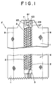
- a slider fastener F comprises a pair of stringer tapes 1, 1 and a pair of rows of coiled type interdigitating fastener elements 2, 2 sewn to the inner longitudinal marginal edges of the respective stringer tapes 1, 1 by means of sewing stitches 3.
- coiled type plastic fastener elements 2, 2 are shown here in the drawings, the invention may apply to other types of fastener elements, such as fastener elements of meander type, injection-molded discrete plastics type, even of metal type.
- a slider 35 (not shown in FIG. 1 but shown in FIG. 6) is mounted for reciprocal movement along the rows of fastener elements 2, 2 to bring the fastener element rows 2, 2 into or out of interdigitating engagement with each other in such a way as it is well known in this field.
- the slider 35 comprises a slider body 37 and a pull tab 39 for manipulating the slider body 37 with.
- the slider body 37 has an attachment lug 41 mounted on its upper surface.
- the pull tab 39 is pivotally mounted on the attachment lug 41.
- the slider body 37 has a flared front end 37a and a converged rear end 37b and has a Y-shaped channel (not shown) formed therethrough.
- the Y-shaped channel is bifurcated at the flared front end 37a; so that, as the fastener element rows 2, 2, move through the Y-shaped channel of the slider 35 from the flared front end 37a, in other words, as the slider 35 moves upward as viewed in FIG. 1, the fastener element rows 2, 2 are brought into interdigitating engagement with each other.
- a bottom end stop 5 is mounted on the lower end of the fastener element rows 2, 2 for preventing the slider 35 from descending therebeyond and slipping off the fastener element rows 2, 2.
- a terminal latch member 61 is mounted on the upper end of the fastener element rows 2, 2 and is adapted for letting the slider 35 move therebeyond and locking the respective upper ends of the fastener element rows 2, 2 to each other, to thus maintain the fastener element rows 2, 2 into interdigitating engagement with each other, as closely described hereinbelow.
- the terminal latch member 61 is made of plastics and integrally formed with the element rows 2, 2 at their upper ends.
- the terminal latch member 61 comprises a pair of opposed first and second lugs 63, 65 mounted on the upper ends of the respective element rows 2, 2.
- the first lug 63 includes a substantially rectangular lug body 67 and an arrow-shaped plug 69 integrally formed with and extending from the inner side of the lug body 67.
- the second lug 65 is substantially rectangular and has a socket 71 formed in the inner side thereof for coupling engagement with the plug 69. As shown in FIGS.
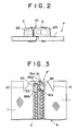
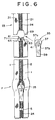
- the width and thickness of the first and the second lug 63, 65 as coupled be dual or slightly less than the width and the thickness of the fastener element rows 2, 2, as coupled, which ensure that, while coupled by the slider 35, the first and second lug 63, 65 let the slider 35 pass beyond themselves and slip off the fastener element rows 2, 2.
- the opposed first and second lugs 63, 65 protrudes upwardly beyond the relevant end edge of the stringer tapes 1, 1 so as to be immune from lateral stresses which might be exerted on the opposed stringer tapes 11, tending to pull them apart.
- the lower ends of the stringer tapes 1, 1 are shown to be cut in corrugated fashion in FIG. 1, however, they may be cut straight, round or in any other fashion.
- the two vertical phantom lines 9, 9 in FIG. 1 indicate the stitching line along which the opposed stringer tapes 1, 1, are sewn to relevant parts of an article, such as a sheet cover for a car seat (not shown).
- the slide fastener F incorporating the bottom end 5 set forth so far lends itself to such an article whose opening no more need to be opened once closed by the slider 35.
- the slider 35 is slid upward along the fastener element rows 2, 2 by pulling up the pull tab 39, thus bringing the fastener element rows 2, 2 into interdigitating engagement with each other.
- the slider 35 moves beyond the terminal latch member 61 so that the slider 35 slips off the slide fastener F and at the same time brings the first and second lug 63, 65 into coupling engagement with each other.
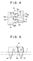
- FIG. 3 shows a slide fastener F' according to a second embodiment of the present invention.
- the slide fastener F' is substantially identical with the slide fastener F according to the first embodiment except for the following points.
- two-plug-two-socket engagement is made on the terminal latch member 81 in this embodiment.
- a pair of arrow-shaped plugs 89a and 89b are integrally formed on and extend protuberantly from the inner side of the lug body 87 of the first lug 83.
- a pair of sockets 91a, 91b are formed in the inner side of the second lug 85 so as to be open toward the first lug 83.
- Each stringer tape 1, 1 has a notch 13 formed on its upper edge adjacent to the terminal latch member 81, which notch 13 extends longitudinally of the tapes 1,1 by the length which is substantially equal to the length of the terminal latch member 81.
- a pair of prongs 14 are integrally formed on the lower side and extend protuberantly downward therefrom.
- the first lug 83 and the second lug 85 are temporarily joined to each other between the plugs 89a, 89b and the corresponding sockets 91a, 91b by a thin and fragile temporary bridge 15a, 15b, respectively.
- the first and second lugs 83, 85 are attached to the respective tapes 1, 1, while remaining joined by the bridge 15a, 15b, by making the prongs 14 pierce the stringer tapes 1, 1 and welding the projecting prongs 14 integrally to the stringer tapes 1, 1. After the attachment of the first and second lugs 83, 85 to the stringer tapes 1, 1, the thin temporary bridge 15a, 15b is broken, thus providing the terminal latch member 81.
- FIG. 6 shows a foremost end of a continuous slide fastener chain 23, a product-length slide fastener F just cut off the continuous slide fastener 23 and now ready for withdrawal to a storing container (not shown), a separate slider 35 ready for insertion into engagement with fastener element rows 2,2.
- the continuous fastener chain 23 comprises a pair of continuous stringer tapes 21, 21 and a succession of fastener element rows 2, 2 mounted at regular intervals on their inner longitudinal marginal edges of the continuous tapes 21, 21 with an element-free space portion 24, 24 interposed between each adjacent fastener element rows 2, 2.
- a slider 35 is threaded from its flared front end 37a through the element -free space portion 24 of the stringer tapes 21, 21 into reciprocal engagement with the foremost fastener element rows 2, 2. After the slider 35 moves up slightly along the fastener element rows 2,2, a bottom stop 5 is mounted on the foremost fastener element rows 2, 2 at their leading ends.
- first and second opposed lugs 63, 65 both made of plastics are mounted on the trailing ends of the respective foremost fastener element rows 2, 2.
- the first lug 63 has the plug 69 extending toward the second lug 65.
- the second lug 65 has the socket 71 open toward the first lug 63 for coupling engagement with the plug 69.
- the width and the thickness of the first and second lug 63, 65 as coupled are equal or slightly less than the width and the thickness, respectively, of the fastener element rows 2, 2 as coupled.
- the continuous slide fastener chain 23 is severed across the ensuing element-free space portion 24, to thus provide a product-length slide fastener F incorporating the slider 35, the bottom stop 5 and the terminal latch member 61.
- the severance of the continuous slide fastener chain 23 is made along such a cutting line that the terminal latch member 61 protrudes beyond the relevant end edge of the stringer tapes 1, 1.
- the end of the stringer tapes 1, 1 which is adjacent to the bottom end stop 5 may be cut in corrugated fashion, as shown in FIGS. 1 and 6, or any other fashion later on.
- each of the first and second lugs 83, 85 has a pair of prongs 14 extending downward from the rear side thereof and disposed longitudinally of the lug 83, 85.
- the first and second. lug 83, 85 are joined by the two temporary thin bridges 15a, 15b.
- the first and second lug 83, 85 thus joined by the temporary bridges 15a, 15b are mounted on the trailing ends of the foremost fastener element rows 2, 2 with the prongs 14 piercing the respective stringer tapes 1, 1.
- the protruding ends of the prongs 14 passing beyond the stringer tapes 1, 1 are welded, such as by ultra-sonic horn, as indicated by phantom lines in FIG.
- the terminal latch member mounted on one end of the fastener element rows may let the slider pass therebeyond and thereafter coupling the respective one end of the fastener element rows to each other, thus keeping the fastener element rows into interdigitating engagement with each other. Therefore, in case that the slide fastener is used on a sheet cover for a car seat, the slide fastener never imparts any offensive feeling to a driver or passengers which would be caused by the conventional slide fastener having a slider left thereon.
- the terminal latch member is free from severe tensions which might be exerted laterally of the stringer tapes, tending to spread them laterally apart.
Landscapes
- Slide Fasteners (AREA)
- Making Paper Articles (AREA)
Claims (7)
- Reißverschluß (F), umfassend zwei Tragbänder (1, 1), zwei miteinander gekuppelte Kuppelgliederreihen (2, 2), die an den inneren Längsrändern der jeweiligen Tragbänder (1, 1) angebracht sind, einen Schieber (35), der auf den Kuppelgliederreihen (2, 2) hin und her beweglich angebracht ist, um die Kuppelgliederreihen miteinander in und außer Eingriff zu bringen, und ein oberes Begrenzungsteil (61), das am oberen Ende der Kuppelgliederreihe (2, 2) angebracht ist, dadurch gekennzeichnet,- daß das obere Begrenzungsteil ein endseitiges Riegelteil (61) ist, umfassend zwei gegenüberliegende erste und zweite Nasen (63, 65; 83, 85), die an den jeweiligen Enden der Kuppelgliederreihen (2, 2) angebracht sind, wobei die erste Nase (63; 83) einen der zweiten Nase (65; 85 zugekehrten Stecker (69; 12) aufweist, wobei die zweite Nase (65; 85) eine Buchse (71) aufweist, die zum Kupplungseingriff mit dem Stecker (69; 12) zu der ersten Nase (63; 85) hin offen ist,- daß die Breite und die Dicke der gekuppelten ersten und zweiten Nasen (63, 65; 83, 85) gleich oder geringfügig kleiner ist als die Breite und die Dicke der gekuppelten Kuppelgliederreihen (2, 2), damit sich der Schieber (35) über das endseitige Riegelteil hinaus bewegen kann, so daß der Schieber von der Reißverschlußkette (F) abgezogen werden kann, und Verriegeln der jeweiligen Enden Kuppelgliederreihen (2, 2) miteinander, um die beiden Kuppelgliederreihen (2, 2) im gekuppelten Zustand zu halten.
- Reißverschluß (F) nach Anspruch 1, wobei ein zusätzliches Paar eines Steckers (89a) und einer zugehörigen Buchse (91a) vorgesehen ist.
- Reißverschluß (F) nach Anspruch 1 oder 2, wobei eine dünne und zerbrechliche zeitweilige Brücke (15a, 15b) zwischen dem Stecker (89a, 89b) und der zugeordneten Buchse (91a, 91b) vorgesehen ist.
- Reißverschluß (F) nach einem der Ansprüche 1 bis 3, wobei das Teil des Tragbandes (1, 1), das dem endseitigen Riegelteil (61) benachbart ist, gegenüber dem übrigen Teil vorspringt und/oder von dem übrigen Teil durch eine Kerbe (13) getrennt ist.
- Reißverschluß (F) nach Anspruch 1, wobei die erste und die zweite Nase (63, 65) jeweils aus Kunststoff hergestellt ist und einen sich von ihrer Rückseite nach hinten erstreckenden Dorn (14) aufweist, wobei jede Nase (63, 65) an dem Ende der zugeordneten Kuppelgliederreihe (2, 2) befestigt ist, indem ihr Dorn (14) durch das zugehörige Tragband (1) hindurchgesteckt und mit diesem einstückig verschweißt wird.
- Verfahren zur Herstellung eines Reißverschlusses (F) aus einer fortlaufenden Reißverschlußkette (23), umfassend die Schritte:- Bereitstellen einer fortlaufenden Reißverschlußkette (23), umfassend zwei fortlaufende Tragbänder (21, 21) und eine Folge von Kuppelgliederreihen (2, 2), die in Abständen an den inneren Längsrändern der fortlaufenden Tragbänder (21, 21) angebracht sind, wobei zwischen benachbarten Kuppelgliederreihen (2, 2) kuppelgliederfreie Bereiche (24, 24) angeordnet sind; und- Aufziehen eines Schiebers (35) mit seinem erweiterten Vorderende (37a) durch den vordersten kuppelgliederfreien Bereich (24, 24) der Tragbänder (21, 21) zum hin und her beweglichen Eingriff mit den vordersten Kuppelgliederreihen (2, 2);- Anbringen eines unteren Begrenzungsteils (5) an den Kuppelgliederreihen (2, 2) an ihrem Vorderende;- Anbringen eines Paares gegenüberliegender erster und zweiter Nasen (63, 65) an den hinteren Enden der vordersten Kuppelgliederreihen (2, 2), wobei die erste Nase (63) einen der zweiten Nase (65) zugekehrten Stecker (69) hat, wobei die zweite Nase (65) eine Buchse (71) hat, die zum Kupplungseingriff mit dem Stecker (69) zu der ersten Nase (63) hin offen ist, wobei die Breite und die Dicke der gekuppelten ersten und zweiten Nasen (63, 65) gleich oder geringfügig kleiner ist als die Breite und die Dicke der gekuppelten Kuppelgliederreihen (2, 2); und- Durchtrennen der fortlaufenden Reißverschlußkette (23) quer zu dem nachfolgenden kuppelgliederfreien Bereich (24).
- Verfahren nach Anspruch 6, wobei die erste und die zweite Nase (63, 65) jeweils aus Kunststoff hergestellt ist und einen sich von ihrer Rückseite nach hinten erstreckenden Dorn (14) aufweist, wobei die erste und die zweite Nase (62, 65) durch eine zeitweilige Brücke (15) verbunden sind; wobei die solchermaßen verbundenen ersten und zweiten Nasen an den Enden der zugeordneten Kuppelgliederreihen (2, 2) angebracht werden, indem ihre Dorne (14) durch die zugeordneten Tragbänder (21, 21) hindurchgedrückt und mit diesen einstückig verschweißt werden, wobei die zeitweilige Brücke (15) beseitigt wird.
Applications Claiming Priority (2)
| Application Number | Priority Date | Filing Date | Title |
|---|---|---|---|
| JP172203/92 | 1992-06-30 | ||
| JP4172203A JP2835336B2 (ja) | 1992-06-30 | 1992-06-30 | スライドファスナーおよびその製造方法 |
Publications (3)
| Publication Number | Publication Date |
|---|---|
| EP0576986A2 EP0576986A2 (de) | 1994-01-05 |
| EP0576986A3 EP0576986A3 (en) | 1994-06-01 |
| EP0576986B1 true EP0576986B1 (de) | 1997-10-29 |
Family
ID=15937501
Family Applications (1)
| Application Number | Title | Priority Date | Filing Date |
|---|---|---|---|
| EP93110015A Expired - Lifetime EP0576986B1 (de) | 1992-06-30 | 1993-06-23 | Reissverschluss und Verfahren zu dessen Herstellung |
Country Status (9)
| Country | Link |
|---|---|
| US (2) | US5400482A (de) |
| EP (1) | EP0576986B1 (de) |
| JP (1) | JP2835336B2 (de) |
| KR (1) | KR940005248A (de) |
| CA (1) | CA2098688C (de) |
| DE (1) | DE69314858T2 (de) |
| ES (1) | ES2110542T3 (de) |
| HK (1) | HK1003592A1 (de) |
| SG (1) | SG99273A1 (de) |
Families Citing this family (11)
| Publication number | Priority date | Publication date | Assignee | Title |
|---|---|---|---|---|
| JPH08313A (ja) * | 1994-06-27 | 1996-01-09 | Ykk Kk | スライドファスナー |
| US6026547A (en) * | 1997-05-15 | 2000-02-22 | O'donnell Kiely; Alice Mary | Immobilized alignment closure system |
| US6780146B2 (en) * | 2002-09-17 | 2004-08-24 | Pactiv Corporation | Methods for applying sliders to reclosable plastic bags |
| US6832415B2 (en) * | 2003-02-13 | 2004-12-21 | Mustang Surgical Corp | Releasable slide fastener closure |
| GB0506680D0 (en) * | 2005-04-01 | 2005-05-11 | Ykk Europ Ltd | A readily burstable slide fastener |
| GB2464766A (en) | 2008-10-30 | 2010-05-05 | Ykk Europ Ltd | Locking stop having split projection |
| JP5978934B2 (ja) * | 2012-11-12 | 2016-08-24 | 豊田合成株式会社 | ステアリングホイール |
| DE102018204809A1 (de) | 2018-03-28 | 2019-10-02 | Autoliv Development Ab | Schließsystem für einen Reißverschluss, Bezugssystem |
| US10646005B2 (en) * | 2018-08-31 | 2020-05-12 | Ykk Corporation Of America | Slide fastener with blocking element |
| CN111602936B (zh) * | 2020-06-10 | 2021-08-13 | 福建浔兴拉链科技股份有限公司 | 一种尼龙拉链缝合机的仿拉头式合链器装置 |
| WO2025203323A1 (ja) * | 2024-03-27 | 2025-10-02 | Ykk株式会社 | 止め具付きスライドファスナー及びスライドファスナー付き製品 |
Citations (1)
| Publication number | Priority date | Publication date | Assignee | Title |
|---|---|---|---|---|
| US4236304A (en) * | 1977-12-30 | 1980-12-02 | Yoshida Kogyo K.K. | Device for spreading apart a pair of tapes |
Family Cites Families (19)
| Publication number | Priority date | Publication date | Assignee | Title |
|---|---|---|---|---|
| GB553551A (en) * | 1941-11-24 | 1943-05-26 | Harry Bertram Grant | Improvements in or relating to sliding clasp fasteners |
| NL248947A (de) * | 1959-03-09 | |||
| US3110904A (en) * | 1962-08-06 | 1963-11-19 | Feinstein Lester | Flap closer and stop for slide fasteners |
| FR1423000A (fr) * | 1964-11-17 | 1966-01-03 | Ailee Fermeture Sa | Fermeture à glissière perfectionnée |
| JPS5031122A (de) * | 1973-07-25 | 1975-03-27 | ||
| CH580403A5 (de) * | 1974-03-08 | 1976-10-15 | Erde Sa | |
| JPS514804A (en) * | 1974-06-28 | 1976-01-16 | Sanwa Kiko Kk | Kishinki oyobi atsunyushirindatsuki aasuoogaa |
| JPS5175886A (en) * | 1974-12-28 | 1976-06-30 | Fuji Electric Co Ltd | Ondochosetsukino dejitarusetsuteikairo |
| US4137608A (en) * | 1977-10-11 | 1979-02-06 | Textron Inc. | Slide fastener with adjustable stop |
| JPS5740805Y2 (de) * | 1978-02-21 | 1982-09-08 | ||
| JPS5925219Y2 (ja) * | 1978-07-31 | 1984-07-25 | ワイケイケイ株式会社 | スライドフアスナ_の下止 |
| JPS5758968U (de) * | 1980-09-24 | 1982-04-07 | ||
| JPS5942895Y2 (ja) * | 1980-11-01 | 1984-12-18 | ワイケイケイ株式会社 | 分割型下止具付きスライドフアスナ− |
| DE3525133A1 (de) * | 1985-07-13 | 1987-01-29 | Opti Patent Forschung Fab | Verfahren und endmontage-automat zur herstellung von mit endteilen, schieber und gegebenenfalls anfangsteilen versehenen, gekuppelten reissverschluessen |
| JPS62148116U (de) * | 1986-03-12 | 1987-09-18 | ||
| JPH0799376B2 (ja) * | 1987-07-23 | 1995-10-25 | 富士通株式会社 | 電圧測定装置 |
| JPH033272A (ja) * | 1989-05-30 | 1991-01-09 | Mitsubishi Electric Corp | 半導体装置 |
| AU620732B2 (en) * | 1989-09-12 | 1992-02-20 | Ykk Corporation | Method of and apparatus for manufacturing slide fasteners |
| DE9017808U1 (de) * | 1990-08-04 | 1992-02-20 | Opti Patent-, Forschungs- Und Fabrikations-Ag, Riedern-Allmeind | Reißverschluß mit textilen Tragbändern und angespritzten Verschlußgliedern |
-
1992
- 1992-06-30 JP JP4172203A patent/JP2835336B2/ja not_active Expired - Fee Related
-
1993
- 1993-06-17 CA CA002098688A patent/CA2098688C/en not_active Expired - Fee Related
- 1993-06-18 US US08/078,105 patent/US5400482A/en not_active Expired - Lifetime
- 1993-06-23 DE DE69314858T patent/DE69314858T2/de not_active Expired - Lifetime
- 1993-06-23 ES ES93110015T patent/ES2110542T3/es not_active Expired - Lifetime
- 1993-06-23 EP EP93110015A patent/EP0576986B1/de not_active Expired - Lifetime
- 1993-06-23 SG SG9600823A patent/SG99273A1/en unknown
- 1993-06-29 KR KR1019930011974A patent/KR940005248A/ko not_active Ceased
-
1994
- 1994-08-19 US US08/293,436 patent/US5443535A/en not_active Expired - Lifetime
-
1998
- 1998-03-27 HK HK98102659A patent/HK1003592A1/en not_active IP Right Cessation
Patent Citations (1)
| Publication number | Priority date | Publication date | Assignee | Title |
|---|---|---|---|---|
| US4236304A (en) * | 1977-12-30 | 1980-12-02 | Yoshida Kogyo K.K. | Device for spreading apart a pair of tapes |
Also Published As
| Publication number | Publication date |
|---|---|
| CA2098688A1 (en) | 1993-12-31 |
| US5443535A (en) | 1995-08-22 |
| JPH0614806A (ja) | 1994-01-25 |
| DE69314858D1 (de) | 1997-12-04 |
| EP0576986A3 (en) | 1994-06-01 |
| ES2110542T3 (es) | 1998-02-16 |
| HK1003592A1 (en) | 1998-10-30 |
| SG99273A1 (en) | 2003-10-27 |
| CA2098688C (en) | 1996-09-03 |
| US5400482A (en) | 1995-03-28 |
| JP2835336B2 (ja) | 1998-12-14 |
| DE69314858T2 (de) | 1998-05-14 |
| EP0576986A2 (de) | 1994-01-05 |
| KR940005248A (ko) | 1994-03-21 |
Similar Documents
| Publication | Publication Date | Title |
|---|---|---|
| CN101411553B (zh) | 反开式拉链 | |
| US5443535A (en) | Method of manufacturing a slide fastener | |
| EP0178585B1 (de) | Reissverschlussschieber mit abnehmbarer Zuglasche | |
| HK1003592B (en) | Slide fastener and method of manufacturing the same | |
| EP2604139B1 (de) | Reissverschluss | |
| CN100579409C (zh) | 拉链咬合链牙和拉链 | |
| US5068950A (en) | Provisional pull tab for slide fastener sliders | |
| US3872551A (en) | Slide fastener having separating end stop | |
| CA1288219C (en) | Automatic locking slider for slide fasteners | |
| EP0210632B1 (de) | Luft- und wasserdichter Reissverschluss | |
| CN1372858A (zh) | 用于拉链的前码装置 | |
| CA1317440C (en) | Separable type water-resistant slide fasteners | |
| US5388312A (en) | Separable bottom stop for concealed type slide fastener | |
| EP0704177B1 (de) | Trennbarer unterer Endanschlag aus synthetischem Harz für Reissverschlüsse | |
| CN209788681U (zh) | 一种使拉链头与左右上止锁定的结构 | |
| US4441235A (en) | Slide fastener with bottom stop | |
| EP0064699A1 (de) | Trennbarer Reissverschluss | |
| EP0287972B1 (de) | Zweiteiliger unterer Endanschlag für Reissverschlüsse | |
| EP0629363B1 (de) | Trennbarer unterer Endanschlag für verdeckte Reissverschlüsse | |
| US5913481A (en) | Separable slide fastener | |
| EP0163936B1 (de) | Trennbarer Reissverschluss | |
| EP0051219A1 (de) | Reissverschluss mit einem unteren teilbaren Endstopp | |
| JPS6349481B2 (de) | ||
| US20050015957A1 (en) | Method and apparatus for assembling slider members onto interlocking fastening strips | |
| HK1014632B (en) | Separable bottom stop for concealed type slide fastener |
Legal Events
| Date | Code | Title | Description |
|---|---|---|---|
| PUAI | Public reference made under article 153(3) epc to a published international application that has entered the european phase |
Free format text: ORIGINAL CODE: 0009012 |
|
| AK | Designated contracting states |
Kind code of ref document: A2 Designated state(s): DE ES FR GB IT |
|
| PUAL | Search report despatched |
Free format text: ORIGINAL CODE: 0009013 |
|
| AK | Designated contracting states |
Kind code of ref document: A3 Designated state(s): DE ES FR GB IT |
|
| 17P | Request for examination filed |
Effective date: 19940831 |
|
| RAP1 | Party data changed (applicant data changed or rights of an application transferred) |
Owner name: YKK CORPORATION |
|
| 17Q | First examination report despatched |
Effective date: 19951228 |
|
| GRAG | Despatch of communication of intention to grant |
Free format text: ORIGINAL CODE: EPIDOS AGRA |
|
| GRAH | Despatch of communication of intention to grant a patent |
Free format text: ORIGINAL CODE: EPIDOS IGRA |
|
| GRAH | Despatch of communication of intention to grant a patent |
Free format text: ORIGINAL CODE: EPIDOS IGRA |
|
| GRAA | (expected) grant |
Free format text: ORIGINAL CODE: 0009210 |
|
| AK | Designated contracting states |
Kind code of ref document: B1 Designated state(s): DE ES FR GB IT |
|
| ITF | It: translation for a ep patent filed | ||
| ET | Fr: translation filed | ||
| REF | Corresponds to: |
Ref document number: 69314858 Country of ref document: DE Date of ref document: 19971204 |
|
| REG | Reference to a national code |
Ref country code: ES Ref legal event code: FG2A Ref document number: 2110542 Country of ref document: ES Kind code of ref document: T3 |
|
| PLBE | No opposition filed within time limit |
Free format text: ORIGINAL CODE: 0009261 |
|
| STAA | Information on the status of an ep patent application or granted ep patent |
Free format text: STATUS: NO OPPOSITION FILED WITHIN TIME LIMIT |
|
| 26N | No opposition filed | ||
| REG | Reference to a national code |
Ref country code: GB Ref legal event code: IF02 |
|
| PGFP | Annual fee paid to national office [announced via postgrant information from national office to epo] |
Ref country code: FR Payment date: 20100709 Year of fee payment: 18 |
|
| PGFP | Annual fee paid to national office [announced via postgrant information from national office to epo] |
Ref country code: IT Payment date: 20100617 Year of fee payment: 18 |
|
| PGFP | Annual fee paid to national office [announced via postgrant information from national office to epo] |
Ref country code: ES Payment date: 20100630 Year of fee payment: 18 |
|
| PGFP | Annual fee paid to national office [announced via postgrant information from national office to epo] |
Ref country code: GB Payment date: 20100623 Year of fee payment: 18 Ref country code: DE Payment date: 20100616 Year of fee payment: 18 |
|
| GBPC | Gb: european patent ceased through non-payment of renewal fee |
Effective date: 20110623 |
|
| PG25 | Lapsed in a contracting state [announced via postgrant information from national office to epo] |
Ref country code: IT Free format text: LAPSE BECAUSE OF NON-PAYMENT OF DUE FEES Effective date: 20110623 |
|
| REG | Reference to a national code |
Ref country code: FR Ref legal event code: ST Effective date: 20120229 |
|
| REG | Reference to a national code |
Ref country code: DE Ref legal event code: R119 Ref document number: 69314858 Country of ref document: DE Effective date: 20120103 |
|
| PG25 | Lapsed in a contracting state [announced via postgrant information from national office to epo] |
Ref country code: DE Free format text: LAPSE BECAUSE OF NON-PAYMENT OF DUE FEES Effective date: 20120103 Ref country code: FR Free format text: LAPSE BECAUSE OF NON-PAYMENT OF DUE FEES Effective date: 20110630 |
|
| PG25 | Lapsed in a contracting state [announced via postgrant information from national office to epo] |
Ref country code: GB Free format text: LAPSE BECAUSE OF NON-PAYMENT OF DUE FEES Effective date: 20110623 |
|
| REG | Reference to a national code |
Ref country code: ES Ref legal event code: FD2A Effective date: 20121116 |
|
| PG25 | Lapsed in a contracting state [announced via postgrant information from national office to epo] |
Ref country code: ES Free format text: LAPSE BECAUSE OF NON-PAYMENT OF DUE FEES Effective date: 20110624 |