EP0577066B1 - Schneidwerkzeug unter Anwendung von aus der Dampfphase abgeschiedenem polykristallinem Diamant für die Schneidkante und Verfahren zu dessen Herstellung - Google Patents
Schneidwerkzeug unter Anwendung von aus der Dampfphase abgeschiedenem polykristallinem Diamant für die Schneidkante und Verfahren zu dessen Herstellung Download PDFInfo
- Publication number
- EP0577066B1 EP0577066B1 EP93110342A EP93110342A EP0577066B1 EP 0577066 B1 EP0577066 B1 EP 0577066B1 EP 93110342 A EP93110342 A EP 93110342A EP 93110342 A EP93110342 A EP 93110342A EP 0577066 B1 EP0577066 B1 EP 0577066B1
- Authority
- EP
- European Patent Office
- Prior art keywords
- diamond
- tool
- layer
- cutting edge
- cutting
- Prior art date
- Legal status (The legal status is an assumption and is not a legal conclusion. Google has not performed a legal analysis and makes no representation as to the accuracy of the status listed.)
- Expired - Lifetime
Links
- 239000010432 diamond Substances 0.000 title claims description 309
- 229910003460 diamond Inorganic materials 0.000 title claims description 309
- 238000005520 cutting process Methods 0.000 title claims description 205
- 238000004519 manufacturing process Methods 0.000 title claims description 18
- 239000000463 material Substances 0.000 claims description 118
- 239000000758 substrate Substances 0.000 claims description 78
- 239000002131 composite material Substances 0.000 claims description 67
- 229910052751 metal Inorganic materials 0.000 claims description 65
- 239000002184 metal Substances 0.000 claims description 65
- 238000005219 brazing Methods 0.000 claims description 62
- 239000000843 powder Substances 0.000 claims description 42
- 239000002245 particle Substances 0.000 claims description 31
- 239000000919 ceramic Substances 0.000 claims description 29
- 239000013078 crystal Substances 0.000 claims description 20
- 238000000034 method Methods 0.000 claims description 20
- 239000000835 fiber Substances 0.000 claims description 17
- 238000007740 vapor deposition Methods 0.000 claims description 16
- 230000012010 growth Effects 0.000 claims description 14
- 238000001465 metallisation Methods 0.000 claims description 13
- 230000000737 periodic effect Effects 0.000 claims description 13
- 230000003746 surface roughness Effects 0.000 claims description 13
- 229910052750 molybdenum Inorganic materials 0.000 claims description 12
- 229910052723 transition metal Inorganic materials 0.000 claims description 10
- 150000003624 transition metals Chemical class 0.000 claims description 10
- 229910052581 Si3N4 Inorganic materials 0.000 claims description 9
- 238000000151 deposition Methods 0.000 claims description 9
- CWYNVVGOOAEACU-UHFFFAOYSA-N Fe2+ Chemical compound [Fe+2] CWYNVVGOOAEACU-UHFFFAOYSA-N 0.000 claims description 8
- 229910052721 tungsten Inorganic materials 0.000 claims description 8
- 150000001247 metal acetylides Chemical class 0.000 claims description 7
- 229910045601 alloy Inorganic materials 0.000 claims description 5
- 239000000956 alloy Substances 0.000 claims description 5
- 229910052742 iron Inorganic materials 0.000 claims description 5
- 229910052759 nickel Inorganic materials 0.000 claims description 5
- 150000004767 nitrides Chemical class 0.000 claims description 5
- OKTJSMMVPCPJKN-UHFFFAOYSA-N Carbon Chemical compound [C] OKTJSMMVPCPJKN-UHFFFAOYSA-N 0.000 claims description 4
- ATJFFYVFTNAWJD-UHFFFAOYSA-N Tin Chemical compound [Sn] ATJFFYVFTNAWJD-UHFFFAOYSA-N 0.000 claims description 4
- 229910052799 carbon Inorganic materials 0.000 claims description 4
- 229910052804 chromium Inorganic materials 0.000 claims description 4
- 229910000601 superalloy Inorganic materials 0.000 claims description 4
- 229910000997 High-speed steel Inorganic materials 0.000 claims description 3
- -1 MO2C Chemical compound 0.000 claims description 3
- 150000001875 compounds Chemical class 0.000 claims description 3
- 229910052715 tantalum Inorganic materials 0.000 claims description 3
- QYEXBYZXHDUPRC-UHFFFAOYSA-N B#[Ti]#B Chemical compound B#[Ti]#B QYEXBYZXHDUPRC-UHFFFAOYSA-N 0.000 claims description 2
- 229910033181 TiB2 Inorganic materials 0.000 claims description 2
- 230000008021 deposition Effects 0.000 claims description 2
- 229910052758 niobium Inorganic materials 0.000 claims description 2
- 229910003470 tongbaite Inorganic materials 0.000 claims description 2
- 229910052720 vanadium Inorganic materials 0.000 claims description 2
- 239000000654 additive Substances 0.000 claims 7
- 230000000996 additive effect Effects 0.000 claims 7
- 239000011159 matrix material Substances 0.000 claims 2
- 238000002144 chemical decomposition reaction Methods 0.000 claims 1
- 239000000945 filler Substances 0.000 description 17
- 239000007789 gas Substances 0.000 description 13
- 239000002994 raw material Substances 0.000 description 12
- 230000015572 biosynthetic process Effects 0.000 description 11
- 239000010408 film Substances 0.000 description 7
- 230000008018 melting Effects 0.000 description 7
- 238000002844 melting Methods 0.000 description 7
- VNWKTOKETHGBQD-UHFFFAOYSA-N methane Chemical compound C VNWKTOKETHGBQD-UHFFFAOYSA-N 0.000 description 7
- 238000005229 chemical vapour deposition Methods 0.000 description 6
- 230000008646 thermal stress Effects 0.000 description 6
- XEEYBQQBJWHFJM-UHFFFAOYSA-N Iron Chemical compound [Fe] XEEYBQQBJWHFJM-UHFFFAOYSA-N 0.000 description 5
- 238000000926 separation method Methods 0.000 description 5
- 239000002253 acid Substances 0.000 description 4
- 230000000052 comparative effect Effects 0.000 description 4
- 238000010586 diagram Methods 0.000 description 4
- 238000004090 dissolution Methods 0.000 description 4
- 239000000203 mixture Substances 0.000 description 4
- 230000008569 process Effects 0.000 description 4
- 238000005245 sintering Methods 0.000 description 4
- 239000000243 solution Substances 0.000 description 4
- 239000010409 thin film Substances 0.000 description 4
- 239000012808 vapor phase Substances 0.000 description 4
- 229910000838 Al alloy Inorganic materials 0.000 description 3
- LFQSCWFLJHTTHZ-UHFFFAOYSA-N Ethanol Chemical compound CCO LFQSCWFLJHTTHZ-UHFFFAOYSA-N 0.000 description 3
- OKKJLVBELUTLKV-UHFFFAOYSA-N Methanol Chemical compound OC OKKJLVBELUTLKV-UHFFFAOYSA-N 0.000 description 3
- 239000011230 binding agent Substances 0.000 description 3
- 239000002826 coolant Substances 0.000 description 3
- 239000001257 hydrogen Substances 0.000 description 3
- 229910052739 hydrogen Inorganic materials 0.000 description 3
- 238000005268 plasma chemical vapour deposition Methods 0.000 description 3
- 230000002829 reductive effect Effects 0.000 description 3
- 230000035882 stress Effects 0.000 description 3
- 239000000126 substance Substances 0.000 description 3
- 238000003786 synthesis reaction Methods 0.000 description 3
- 230000003685 thermal hair damage Effects 0.000 description 3
- XKRFYHLGVUSROY-UHFFFAOYSA-N Argon Chemical compound [Ar] XKRFYHLGVUSROY-UHFFFAOYSA-N 0.000 description 2
- 239000004215 Carbon black (E152) Substances 0.000 description 2
- 229910001018 Cast iron Inorganic materials 0.000 description 2
- KRHYYFGTRYWZRS-UHFFFAOYSA-N Fluorane Chemical compound F KRHYYFGTRYWZRS-UHFFFAOYSA-N 0.000 description 2
- UFHFLCQGNIYNRP-UHFFFAOYSA-N Hydrogen Chemical compound [H][H] UFHFLCQGNIYNRP-UHFFFAOYSA-N 0.000 description 2
- 229910003178 Mo2C Inorganic materials 0.000 description 2
- 229910019802 NbC Inorganic materials 0.000 description 2
- ATUOYWHBWRKTHZ-UHFFFAOYSA-N Propane Chemical compound CCC ATUOYWHBWRKTHZ-UHFFFAOYSA-N 0.000 description 2
- 229910000831 Steel Inorganic materials 0.000 description 2
- 230000003213 activating effect Effects 0.000 description 2
- 230000008859 change Effects 0.000 description 2
- 238000006243 chemical reaction Methods 0.000 description 2
- 239000003795 chemical substances by application Substances 0.000 description 2
- 238000003776 cleavage reaction Methods 0.000 description 2
- 229930195733 hydrocarbon Natural products 0.000 description 2
- 150000002430 hydrocarbons Chemical class 0.000 description 2
- 238000003754 machining Methods 0.000 description 2
- 230000002787 reinforcement Effects 0.000 description 2
- 230000007017 scission Effects 0.000 description 2
- 229910000679 solder Inorganic materials 0.000 description 2
- 238000005507 spraying Methods 0.000 description 2
- 239000010959 steel Substances 0.000 description 2
- 230000002194 synthesizing effect Effects 0.000 description 2
- 229910003468 tantalcarbide Inorganic materials 0.000 description 2
- UGFAIRIUMAVXCW-UHFFFAOYSA-N Carbon monoxide Chemical compound [O+]#[C-] UGFAIRIUMAVXCW-UHFFFAOYSA-N 0.000 description 1
- 229910000881 Cu alloy Inorganic materials 0.000 description 1
- OTMSDBZUPAUEDD-UHFFFAOYSA-N Ethane Chemical compound CC OTMSDBZUPAUEDD-UHFFFAOYSA-N 0.000 description 1
- GRYLNZFGIOXLOG-UHFFFAOYSA-N Nitric acid Chemical compound O[N+]([O-])=O GRYLNZFGIOXLOG-UHFFFAOYSA-N 0.000 description 1
- 229910000676 Si alloy Inorganic materials 0.000 description 1
- 229910034327 TiC Inorganic materials 0.000 description 1
- QZPSXPBJTPJTSZ-UHFFFAOYSA-N aqua regia Chemical compound Cl.O[N+]([O-])=O QZPSXPBJTPJTSZ-UHFFFAOYSA-N 0.000 description 1
- 229910052786 argon Inorganic materials 0.000 description 1
- QVGXLLKOCUKJST-UHFFFAOYSA-N atomic oxygen Chemical compound [O] QVGXLLKOCUKJST-UHFFFAOYSA-N 0.000 description 1
- 150000001722 carbon compounds Chemical class 0.000 description 1
- 229910002091 carbon monoxide Inorganic materials 0.000 description 1
- 239000011195 cermet Substances 0.000 description 1
- 238000002485 combustion reaction Methods 0.000 description 1
- 230000006835 compression Effects 0.000 description 1
- 238000007906 compression Methods 0.000 description 1
- 238000001816 cooling Methods 0.000 description 1
- 238000009826 distribution Methods 0.000 description 1
- 230000000694 effects Effects 0.000 description 1
- 230000003628 erosive effect Effects 0.000 description 1
- 150000002148 esters Chemical class 0.000 description 1
- 238000001704 evaporation Methods 0.000 description 1
- 230000008020 evaporation Effects 0.000 description 1
- 239000002657 fibrous material Substances 0.000 description 1
- 239000010439 graphite Substances 0.000 description 1
- 229910002804 graphite Inorganic materials 0.000 description 1
- 238000010438 heat treatment Methods 0.000 description 1
- 150000002431 hydrogen Chemical class 0.000 description 1
- 239000011261 inert gas Substances 0.000 description 1
- 230000002401 inhibitory effect Effects 0.000 description 1
- 150000002739 metals Chemical class 0.000 description 1
- VUZPPFZMUPKLLV-UHFFFAOYSA-N methane;hydrate Chemical compound C.O VUZPPFZMUPKLLV-UHFFFAOYSA-N 0.000 description 1
- 239000013081 microcrystal Substances 0.000 description 1
- 238000003801 milling Methods 0.000 description 1
- 239000011259 mixed solution Substances 0.000 description 1
- 229910003465 moissanite Inorganic materials 0.000 description 1
- 229910017604 nitric acid Inorganic materials 0.000 description 1
- 229910052760 oxygen Inorganic materials 0.000 description 1
- 239000001301 oxygen Substances 0.000 description 1
- 238000002360 preparation method Methods 0.000 description 1
- 239000001294 propane Substances 0.000 description 1
- 230000001681 protective effect Effects 0.000 description 1
- 230000009467 reduction Effects 0.000 description 1
- 230000001105 regulatory effect Effects 0.000 description 1
- 230000035939 shock Effects 0.000 description 1
- 229910010271 silicon carbide Inorganic materials 0.000 description 1
- 238000004544 sputter deposition Methods 0.000 description 1
- 238000001947 vapour-phase growth Methods 0.000 description 1
- XLYOFNOQVPJJNP-UHFFFAOYSA-N water Substances O XLYOFNOQVPJJNP-UHFFFAOYSA-N 0.000 description 1
- 229910001868 water Inorganic materials 0.000 description 1
Images


Classifications
-
- C—CHEMISTRY; METALLURGY
- C23—COATING METALLIC MATERIAL; COATING MATERIAL WITH METALLIC MATERIAL; CHEMICAL SURFACE TREATMENT; DIFFUSION TREATMENT OF METALLIC MATERIAL; COATING BY VACUUM EVAPORATION, BY SPUTTERING, BY ION IMPLANTATION OR BY CHEMICAL VAPOUR DEPOSITION, IN GENERAL; INHIBITING CORROSION OF METALLIC MATERIAL OR INCRUSTATION IN GENERAL
- C23C—COATING METALLIC MATERIAL; COATING MATERIAL WITH METALLIC MATERIAL; SURFACE TREATMENT OF METALLIC MATERIAL BY DIFFUSION INTO THE SURFACE, BY CHEMICAL CONVERSION OR SUBSTITUTION; COATING BY VACUUM EVAPORATION, BY SPUTTERING, BY ION IMPLANTATION OR BY CHEMICAL VAPOUR DEPOSITION, IN GENERAL
- C23C16/00—Chemical coating by decomposition of gaseous compounds, without leaving reaction products of surface material in the coating, i.e. chemical vapour deposition [CVD] processes
- C23C16/22—Chemical coating by decomposition of gaseous compounds, without leaving reaction products of surface material in the coating, i.e. chemical vapour deposition [CVD] processes characterised by the deposition of inorganic material, other than metallic material
- C23C16/26—Deposition of carbon only
- C23C16/27—Diamond only
- C23C16/278—Diamond only doping or introduction of a secondary phase in the diamond
-
- B—PERFORMING OPERATIONS; TRANSPORTING
- B23—MACHINE TOOLS; METAL-WORKING NOT OTHERWISE PROVIDED FOR
- B23P—METAL-WORKING NOT OTHERWISE PROVIDED FOR; COMBINED OPERATIONS; UNIVERSAL MACHINE TOOLS
- B23P15/00—Making specific metal objects by operations not covered by a single other subclass or a group in this subclass
- B23P15/28—Making specific metal objects by operations not covered by a single other subclass or a group in this subclass cutting tools
-
- C—CHEMISTRY; METALLURGY
- C23—COATING METALLIC MATERIAL; COATING MATERIAL WITH METALLIC MATERIAL; CHEMICAL SURFACE TREATMENT; DIFFUSION TREATMENT OF METALLIC MATERIAL; COATING BY VACUUM EVAPORATION, BY SPUTTERING, BY ION IMPLANTATION OR BY CHEMICAL VAPOUR DEPOSITION, IN GENERAL; INHIBITING CORROSION OF METALLIC MATERIAL OR INCRUSTATION IN GENERAL
- C23C—COATING METALLIC MATERIAL; COATING MATERIAL WITH METALLIC MATERIAL; SURFACE TREATMENT OF METALLIC MATERIAL BY DIFFUSION INTO THE SURFACE, BY CHEMICAL CONVERSION OR SUBSTITUTION; COATING BY VACUUM EVAPORATION, BY SPUTTERING, BY ION IMPLANTATION OR BY CHEMICAL VAPOUR DEPOSITION, IN GENERAL
- C23C16/00—Chemical coating by decomposition of gaseous compounds, without leaving reaction products of surface material in the coating, i.e. chemical vapour deposition [CVD] processes
- C23C16/01—Chemical coating by decomposition of gaseous compounds, without leaving reaction products of surface material in the coating, i.e. chemical vapour deposition [CVD] processes on temporary substrates, e.g. substrates subsequently removed by etching
-
- C—CHEMISTRY; METALLURGY
- C23—COATING METALLIC MATERIAL; COATING MATERIAL WITH METALLIC MATERIAL; CHEMICAL SURFACE TREATMENT; DIFFUSION TREATMENT OF METALLIC MATERIAL; COATING BY VACUUM EVAPORATION, BY SPUTTERING, BY ION IMPLANTATION OR BY CHEMICAL VAPOUR DEPOSITION, IN GENERAL; INHIBITING CORROSION OF METALLIC MATERIAL OR INCRUSTATION IN GENERAL
- C23C—COATING METALLIC MATERIAL; COATING MATERIAL WITH METALLIC MATERIAL; SURFACE TREATMENT OF METALLIC MATERIAL BY DIFFUSION INTO THE SURFACE, BY CHEMICAL CONVERSION OR SUBSTITUTION; COATING BY VACUUM EVAPORATION, BY SPUTTERING, BY ION IMPLANTATION OR BY CHEMICAL VAPOUR DEPOSITION, IN GENERAL
- C23C16/00—Chemical coating by decomposition of gaseous compounds, without leaving reaction products of surface material in the coating, i.e. chemical vapour deposition [CVD] processes
- C23C16/22—Chemical coating by decomposition of gaseous compounds, without leaving reaction products of surface material in the coating, i.e. chemical vapour deposition [CVD] processes characterised by the deposition of inorganic material, other than metallic material
- C23C16/26—Deposition of carbon only
- C23C16/27—Diamond only
- C23C16/271—Diamond only using hot filaments
-
- C—CHEMISTRY; METALLURGY
- C23—COATING METALLIC MATERIAL; COATING MATERIAL WITH METALLIC MATERIAL; CHEMICAL SURFACE TREATMENT; DIFFUSION TREATMENT OF METALLIC MATERIAL; COATING BY VACUUM EVAPORATION, BY SPUTTERING, BY ION IMPLANTATION OR BY CHEMICAL VAPOUR DEPOSITION, IN GENERAL; INHIBITING CORROSION OF METALLIC MATERIAL OR INCRUSTATION IN GENERAL
- C23C—COATING METALLIC MATERIAL; COATING MATERIAL WITH METALLIC MATERIAL; SURFACE TREATMENT OF METALLIC MATERIAL BY DIFFUSION INTO THE SURFACE, BY CHEMICAL CONVERSION OR SUBSTITUTION; COATING BY VACUUM EVAPORATION, BY SPUTTERING, BY ION IMPLANTATION OR BY CHEMICAL VAPOUR DEPOSITION, IN GENERAL
- C23C16/00—Chemical coating by decomposition of gaseous compounds, without leaving reaction products of surface material in the coating, i.e. chemical vapour deposition [CVD] processes
- C23C16/22—Chemical coating by decomposition of gaseous compounds, without leaving reaction products of surface material in the coating, i.e. chemical vapour deposition [CVD] processes characterised by the deposition of inorganic material, other than metallic material
- C23C16/26—Deposition of carbon only
- C23C16/27—Diamond only
- C23C16/276—Diamond only using plasma jets
-
- C—CHEMISTRY; METALLURGY
- C23—COATING METALLIC MATERIAL; COATING MATERIAL WITH METALLIC MATERIAL; CHEMICAL SURFACE TREATMENT; DIFFUSION TREATMENT OF METALLIC MATERIAL; COATING BY VACUUM EVAPORATION, BY SPUTTERING, BY ION IMPLANTATION OR BY CHEMICAL VAPOUR DEPOSITION, IN GENERAL; INHIBITING CORROSION OF METALLIC MATERIAL OR INCRUSTATION IN GENERAL
- C23C—COATING METALLIC MATERIAL; COATING MATERIAL WITH METALLIC MATERIAL; SURFACE TREATMENT OF METALLIC MATERIAL BY DIFFUSION INTO THE SURFACE, BY CHEMICAL CONVERSION OR SUBSTITUTION; COATING BY VACUUM EVAPORATION, BY SPUTTERING, BY ION IMPLANTATION OR BY CHEMICAL VAPOUR DEPOSITION, IN GENERAL
- C23C28/00—Coating for obtaining at least two superposed coatings either by methods not provided for in a single one of groups C23C2/00 - C23C26/00 or by combinations of methods provided for in subclasses C23C and C25C or C25D
- C23C28/04—Coating for obtaining at least two superposed coatings either by methods not provided for in a single one of groups C23C2/00 - C23C26/00 or by combinations of methods provided for in subclasses C23C and C25C or C25D only coatings of inorganic non-metallic material
- C23C28/044—Coating for obtaining at least two superposed coatings either by methods not provided for in a single one of groups C23C2/00 - C23C26/00 or by combinations of methods provided for in subclasses C23C and C25C or C25D only coatings of inorganic non-metallic material coatings specially adapted for cutting tools or wear applications
-
- C—CHEMISTRY; METALLURGY
- C23—COATING METALLIC MATERIAL; COATING MATERIAL WITH METALLIC MATERIAL; CHEMICAL SURFACE TREATMENT; DIFFUSION TREATMENT OF METALLIC MATERIAL; COATING BY VACUUM EVAPORATION, BY SPUTTERING, BY ION IMPLANTATION OR BY CHEMICAL VAPOUR DEPOSITION, IN GENERAL; INHIBITING CORROSION OF METALLIC MATERIAL OR INCRUSTATION IN GENERAL
- C23C—COATING METALLIC MATERIAL; COATING MATERIAL WITH METALLIC MATERIAL; SURFACE TREATMENT OF METALLIC MATERIAL BY DIFFUSION INTO THE SURFACE, BY CHEMICAL CONVERSION OR SUBSTITUTION; COATING BY VACUUM EVAPORATION, BY SPUTTERING, BY ION IMPLANTATION OR BY CHEMICAL VAPOUR DEPOSITION, IN GENERAL
- C23C28/00—Coating for obtaining at least two superposed coatings either by methods not provided for in a single one of groups C23C2/00 - C23C26/00 or by combinations of methods provided for in subclasses C23C and C25C or C25D
- C23C28/04—Coating for obtaining at least two superposed coatings either by methods not provided for in a single one of groups C23C2/00 - C23C26/00 or by combinations of methods provided for in subclasses C23C and C25C or C25D only coatings of inorganic non-metallic material
- C23C28/048—Coating for obtaining at least two superposed coatings either by methods not provided for in a single one of groups C23C2/00 - C23C26/00 or by combinations of methods provided for in subclasses C23C and C25C or C25D only coatings of inorganic non-metallic material with layers graded in composition or physical properties
-
- C—CHEMISTRY; METALLURGY
- C23—COATING METALLIC MATERIAL; COATING MATERIAL WITH METALLIC MATERIAL; CHEMICAL SURFACE TREATMENT; DIFFUSION TREATMENT OF METALLIC MATERIAL; COATING BY VACUUM EVAPORATION, BY SPUTTERING, BY ION IMPLANTATION OR BY CHEMICAL VAPOUR DEPOSITION, IN GENERAL; INHIBITING CORROSION OF METALLIC MATERIAL OR INCRUSTATION IN GENERAL
- C23C—COATING METALLIC MATERIAL; COATING MATERIAL WITH METALLIC MATERIAL; SURFACE TREATMENT OF METALLIC MATERIAL BY DIFFUSION INTO THE SURFACE, BY CHEMICAL CONVERSION OR SUBSTITUTION; COATING BY VACUUM EVAPORATION, BY SPUTTERING, BY ION IMPLANTATION OR BY CHEMICAL VAPOUR DEPOSITION, IN GENERAL
- C23C30/00—Coating with metallic material characterised only by the composition of the metallic material, i.e. not characterised by the coating process
- C23C30/005—Coating with metallic material characterised only by the composition of the metallic material, i.e. not characterised by the coating process on hard metal substrates
Definitions
- the present invention relates to a diamond cutting tool, and more particularly, it relates to a cutting tool employing diamond which is formed by vapor deposition for its cutting edge and having excellent wear resistance and chipping resistance, and a method of manufacturing the same.
- Diamond having high hardness and high thermal conductivity, is particularly useful as a tool material for cutting a nonferrous metal such as a Al alloy, graphite or ceramics.
- Diamond materials which are applied to tool materials are classified into monocrystal and polycrystalline materials.
- Monocrystal diamond which is excellent in physical characteristics, has disadvantages of remarkable expensiveness, difficulty in working into a desired shape as a tool material, and cleavage.
- polycrystalline diamond materials for serving as tool materials can be roughly divided in two types.
- the first one is sintered diamond, which is obtained by sintering fine diamond powder and an iron family metal such as Co under diamond-stable extra-high pressure and high-temperature conditions.
- sintered diamond which is obtained by sintering fine diamond powder and an iron family metal such as Co under diamond-stable extra-high pressure and high-temperature conditions.
- an iron family metal such as Co under diamond-stable extra-high pressure and high-temperature conditions.
- Such a sintering technique is described in Japanese Patent Publication No. 52-12126 (1977), for example.
- such sintered diamond contains several to several 10 % of binder, a cutting edge of such diamond may be chipped due to falling of diamond particles forming the sintered body during cutting.
- Such a falling phenomenon remarkably appears as a wedge angle of the tool cutting edge is reduced, and it is difficult to ensure a long life in a sharp cutting edge of sintered diamond. Due to the binder contained therein, further, the sintered diamond is so inferior in heat resistance to the monocrystal diamond that the same is easily worn during cutting.
- vapor-deposited diamond which is another type of polycrystalline diamond for a cutting tool, is superior in heat resistance and wear resistance to the sintered diamond and hard to chip, since the same is dense and formed of only diamond.
- vapor-deposited diamond is generally prepared by chemical vapor deposition (CVD) of decomposing/exciting a raw material gas which is mainly composed of hydrocarbon such as methane and hydrogen under a low pressure.
- a diamond-coated tool comprising a tool substrate which is directly coated with diamond has been developed as a cutting tool employing vapor-deposited diamond.
- adhesion between the tool substrate and the as-formed diamond thin film is important.
- a tool prepared by forming a diamond thin film on a substrate of cemented carbide for example, there has been a problem that the diamond thin film separates from the substrate during cutting.
- each of Japanese Patent Laying-Open Nos. 1-153228 (1989) and 1-210201 (1989) discloses a technique of brazing a thick film of vapor-deposited diamond as a cutting edge to a tool substrate of cemented carbide for providing a cutting tool.
- Such a tool causes no problem of separation of diamond dissimilarly to the diamond-coated tool, and is superior in performance to the conventional tool employing sintered diamond.
- a cutting tool having a cutting edge member of vapor-deposited polycrystalline diamond is superior in strength, wear resistance and heat resistance to a conventional tool employing a diamond sintered body.
- a brazing filler metal having a melting point of about 650°C is employed similarly to the tool employing a diamond sintered body, in order to braze the cutting edge member to a tool substrate.
- the cutting tool employing vapor-deposited diamond is easily exposed to thermal damage with respect to a brazing layer by the heat generated from the cutting edge during cutting, as compared with the tool employing sintered diamond, since the vapor-deposited diamond has higher thermal conductivity than the diamond sintered body.
- the brazing layer is softened by heat and deformed during cutting, the cutting edge of vapor-deposited diamond is chipped.
- a sharp cutting edge having a wedge angle of not more than 65° is formed in a diamond tool which is manufactured by brazing vapor-deposited diamond to a tool substrate, further, the cutting edge is easily chipped if high stress or an impact load is applied to the cutting edge in intermittent cutting or cutting of hard ceramics.
- EP-A-469 204 discloses a method of producing a diamond film on an object to be treated, comprising the steps of forming a first intermediate layer and then forming a second intermediate layer on the first intermediate layer and than forming a diamond film on the second intermediate layer.
- the first intermediate layer is composed of a mixture of a main component element of the objects to be treated and a component element of a sintering reinforcement agent.
- the second intermediate layer is composed of a mixture of the component element of the sintering reinforcement agent and diamond (see e.g. page 10, lines 19 - 26).
- the citation discloses forming a diamond film and intermediate layer is directly on a tool substrate rather than on a forming a substrate as according to the present invention.
- JP-A-1212767 discloses a highly wear resistant polycrystalline diamond tool and its production wherein the polycrystalline diamond essentially consisting of diamond alone is deposited to 0.1-3.0 mm thickness by a low-pressure vapor phase process on a substrate and wherein the polycrystalline diamond side is brazed to a supporting member by means of an alloy brazing filler metal so that the thickness of the alloy brazing filler metal is regulated to a defined thickness.
- this cited document is not directed to a diamond cutting tool comprising a substrate and a laminated structure of three layers.
- An object of the present invention is to provide a diamond cutting tool having a cutting edge which is easy to braze with a brazing filler metal and is hardly damaged by heat with respect to the brazing material.
- Another object of the present invention is to provide a diamond cutting tool having high strength and excellent durability.
- the diamond cutting tool comprises a tool substrate, and a cutting edge member, which is provided on the tool substrate, containing vapor-deposited polycrystalline diamond.
- the cutting edge member includes three layers.
- the first layer consists essentially of vapor-deposited polycrystalline diamond, and forms a rake face of a cutting edge.
- the second layers, which is formed on the first layer consists essentially of a metal and a ceramic having a linear expansion coefficient between that of the tool substrate and that of the diamond or closer to that of the substrate than the diamond, and vapor-deposited polycrystal diamond.
- the third layer which is formed on the second layer, consists essentially of said metal. The cutting edge member having such a laminate structure is brazed to the tool substrate through the third layer.
- a method for manufacturing such a diamond cutting tool comprises a step of forming a diamond layer on a base material by vapor deposition, a step of depositing diamond on the diamond layer by vapor deposition while supplying powder of a metal and a ceramic both having a thermal expansion coefficient between that of the tool substrate and the diamond or closer to that of the substrate than the diamond, in a vapor phase, a step of then stopping such synthesis of the diamond and depositing said metal, a step of separating or removing the base material for obtaining a cutting edge member having a laminate structure, and a step of brazing the cutting edge member to a tool substrate so that a surface of the diamond layer which has been in contact with the base material defines a rake face.
- a cutting edge member which is provided on a tool substrate comprises a portion defining a rake face of a cutting edge and consisting essentially of a diamond composite material.
- This diamond composite material consists essentially of particles or fibers consisting essentially of at least one material selected from the group consisting of Si, B, Ge and transition metals belonging to the groups IVa, Va and VIa of the periodic table, oxides, nitrides, carbides, carbo-nitrides and borides of B, Al, Si and transition metals belonging to the groups IVa, Va and Via of the periodic table, and diamond, and vapor-deposited polycrystalline diamond strongly bonding the particles or fibers.
- a method for manufacturing such a diamond cutting tool comprises a step of preparing a base material having a mirror-finished surface, a step of depositing diamond on the surface by vapor deposition while supplying the surface with particles or fibers consisting essentially of at least one material selected from the group consisting of Si, B, Ge and transition metals belonging to the groups IVa, Va and VIa of the periodic table, oxides, nitrides, carbides, carbo-nitrides and borides of B, Al, Si and transition metals belonging to the groups IVa, Va and VIa of the periodic table, and diamond, a step of separating or removing the base material thereby obtaining a diamond composite material consisting essentially of the aforementioned material and polycrystalline diamond strongly bonding the material, and a step of brazing the diamond composite material to a tool substrate so that a surface of the diamond composite material having been in contact with the base material defines a rake face of a cutting edge.
- a method of decomposing and exciting a raw material gas with a thermal filament or plasma discharge and a film forming method employing a combustion flame are useful for vapor deposition of diamond.
- a raw material gas can be prepared from a gas which is mainly composed of hydrocarbon such as methane, ethane or propane, alcohol such as methanol or ethanol or an organic carbon compound such as ester, and hydrogen.
- the raw material can contain inert gas such as argon, oxygen, carbon monoxide and water, in a range not inhibiting synthesis of diamond and its characteristics.
- the tool substrate may be prepared from a heat resistant composite material such as cemented carbide or cermet, a heat resistant alloy such as cast iron or a super alloy, steel such as high-speed steel, or the like.
- Mo, W, Cr, V, Nb, Ta, Co, Ni or Fe can be employed as the metal which is contained in the cutting edge member, for example, while cBN, SiC, Si 3 N 4 , WC, BN, TiC, TaC, NbC, Cr 3 C 2 , Mo 2 C, VC or TiN can be employed as ceramics, for example.
- proper ones are preferably appropriately selected or combined with each other in consideration of adhesion to diamond and that to the tool substrate, as well as a linear expansion coefficient.
- SiC, Si 3 N 4 , WC, BN, W and Mo are more preferable as to adhesion to the vapor-deposited diamond, while cBN, SiC, Si 3 N 4 , WC, hBN, W and Mo are excellent in adhesion to diamond in this order.
- Mo, W, WC, TiC, Cr, Co, Ni and Fe are preferable, depending on the type of the tool substrate.
- the cutting edge which is closer to the tool substrate, for example, while introducing a large amount of cBN, SiC, Si 3 N 4 , WC, BN, W or Mo into another portion of the cutting edge closer to the diamond layer.
- the SiC, Si 3 N 4 , W and Mo are preferably used together with the tool substrate of a cemented carbide.
- the cutting edge having a three-layer structure is brazed to the tool substrate.
- a brazing filler metal for such brazing can be prepared from soft solder having a brazing temperature of about 250 to 450°C or silver solder, corresponding to JIS B Ag-3, having a brazing temperature of about 600 to 700°C, for example.
- the brazing can be preferably performed through a metallization layer which is formed of a metal or semi-metal element belonging to the groups IIIb, IVa, IVb, Va, Vb, VIa, VIb, VIIa and VIII of the periodic table, or a compound thereof.
- the cutting edge having a three-layer structure can have a thickness of about 20 to 5000 ⁇ m, more preferably about 100 to 1000 ⁇ m.
- the first layer (diamond layer) is started from a surface of the base material.
- the cutting edge member is brazed to the tool substrate so that the surface of the diamond layer having been in contact with the base material defines a rake face, the maximum amount of diamond having the minimum crystal grain diameter is present in the rake face of the diamond layer.
- the thickness of the first layer is preferably at least about 40 ⁇ m, and more preferably at least about 70 ⁇ m.
- the second layer (composite layer) preferably has a thickness of about 10 to 300 ⁇ m, more preferably about 30 to 100 ⁇ m.
- the diamond content can be about 0.5 to 99 percent by volume, for example, while the content of the metal and ceramic can be about 1 to 99.5 percent by volume, for example. Further, the diamond content is more preferably inclined to be successively reduced toward the third layer.
- the third layer consisting essentially of said metal preferably has a thickness of about 50 to 2000 ⁇ m, and more preferably about 100 to 1000 ⁇ m, for example.
- a tool comprising a cutting edge member having a twisted shape such as a helical flute, which is brazed to a tool substrate.
- a tool is applicable to various milling cutters and drills.
- the rake face is preferably so smooth that its surface roughness R max is not more than about 0.2 ⁇ m, for example.
- the base material to be provided with the diamond layer (first layer) is preferably prepared from Si, Mo or the like, for example. Such a base material can be separated from the diamond layer by separation or dissolution through machining or chemical treatment.
- the surface of the base material to be provided with the diamond layer is preferably mirror-finished so that its surface roughness R max is not more than about 0.2 ⁇ m.
- the diamond layer can be formed in a thickness of at least about 40 ⁇ m, more preferably at least about 70 ⁇ m, for example.
- the metal powder and ceramics powder supplied in the vapor phase can be prepared from the aforementioned material.
- the particle diameter of such powder is preferably about 0.1 to 150 ⁇ m, and more preferably about 0.2 to 60 ⁇ m, for example.
- This powder can be so supplied into a flow of the raw material gas which is employed for vapor deposition of the diamond, to deposit onto the base material with the diamond.
- the powder may be in a temporarily completely melted state, a semi-melted state, or an unmelted state. Formation of a film with such supply of the powder, which can be carried out by well-known CVD, for example, is preferably carried out in accordance with a spraying process employing high-temperature plasma CVD.
- a composite layer (second layer) is so formed as to contain the metal and ceramic and the diamond in a mixed state.
- the thickness of such a composite layer is preferably about 10 to 300 ⁇ m, more preferably about 30 to 100 ⁇ m.
- the layer of said metal deposited on the composite layer which can be formed by well-known evaporation or sputtering, for example, can be preferably formed by continuing the aforementioned spraying process.
- the layer of said metal formed in such a manner can have a thickness of about 50 to 2000 ⁇ m, more preferably about 100 to 1000 ⁇ m.
- the deposit formed in the aforementioned manner is separated by dissolution/removal of the base material or the like. The deposit may be worked with a laser in advance of such separation, or laser-worked into a prescribed shape after the separation.
- the aforementioned cutting edge member having a multilayer structure can be subjected to cutting edge treatment such as honing or formation of a negative land after brazing and preparing edge.
- the rake face consisting essentially of polycrystalline diamond provides the tool with excellent heat resistance, wear resistance and chipping resistance.
- the rake face has a fine structure in the initial stage of growth, and is formed of diamond crystals having the minimum particle diameter in the diamond layer.
- the rake face formed of such a fine structure is particularly excellent in wear resistance and chipping resistance.
- More important parts are the second layer which is formed following the first layer, and the third layer which is formed following the second layer.
- the second layer contains a metal and a ceramic and diamond in a mixed state, while the third layer consists essentially of said metal.
- the metal and/or the ceramics forming these layers is smaller in thermal conductivity than diamond. Thus, these layers are hard to transfer heat as compared with the diamond layer.
- the cutting edge is brazed through the third layer, whereby heat which is generated in the first layer (diamond layer) of the cutting edge during cutting is transferred to a brazing layer through the second and third layers. Since the second and third layers are hard to transfer heat as compared with diamond, the heat generated in the cutting edge is hardly transferred to the brazing layer as compared with the conventional tool having a cutting edge which is formed of only diamond, whereby the brazing layer is hardly exposed to thermal damage.
- the metal or the metal and the ceramic forming the second and third layers has have a linear expansion coefficient which is between that of the tool substrate and diamond or is closer to that of the substrate than the diamond.
- the cutting edge is brazed through the third layer. Since, a portion concerning brazing is formed of a material having a linear expansion coefficient which is closer to that of the tool substrate, it is possible to remarkably suppress thermal stress which is caused by difference in linear expansion coefficient as compared with the case of directly brazing diamond.
- the second layer is adapted to suppress heat conduction as described above, as well as to strongly bond the third layer, which is suitable for brazing, with the diamond layer. If this layer is not provided, the diamond layer forming the cutting edge is easily separated, leading to inferior durability of the cutting tool.
- a diamond material generally forming a cutting edge diamond is deformed in removal of a base material when the diamond material formed on the base material is small in thickness. Such deformation is particularly problematic in manufacturing of a cutting edge, such as a helical flute, other than a flat plate. The thickness of the diamond material may be increased in order to avoid such a problem, while such a thick diamond material is increased in cost.
- the cost for the cutting edge can be reduced by forming a cutting edge containing diamond and other low-priced material in a mixed state and the diamond layer forming the rake face is strongly supported, while the cutting edge is remarkably inhibited from deformation caused by thermal stress or the like.
- the powder of a metal and a ceramic may be in a melted, semi-melted or unmelted state.
- diamond can be grown from nuclei of particles forming the powder, so that a composite layer containing vapor-deposited diamond serving as a binder can be obtained. In this composite layer, adhesion between diamond and the powder particles is excellent.
- synthesis of the diamond is stopped so that a layer of said metal is formed on the second layer.
- the deposit of the three layers is separated from the base material, and brazed to a tool substrate as a cutting edge member. In such brazing, a surface of the diamond layer having been in contact with the base material defines a rake face.
- the brazing is carried out through the layer of said metal.
- the surface of the base material on which the diamond layer is deposited is smoothed, it is possible to obtain a smooth rake face by such brazing.
- the surface of the diamond layer having been in contact with the base material has a fine structure which is excellent in wear resistance and chipping resistance as hereinabove described, since vapor deposition has been started from this portion.
- the cutting edge member having lower thermal conductivity than a conventional diamond cutting edge is brazed to the tool substrate.
- a base of cemented carbide it is possible to suppress thermal damage to the brazing layer in cutting even if a brazing filler metal having a melting point of about 650°C is employed, similarly to the prior art.
- the brazing can be easily carried out with no requirement for specific consideration.
- a material which must be composed with vapor-deposited diamond can be in the form of powder, fibers, or a mixture thereof.
- a powder material When a powder material is employed, its mean particle diameter is preferably not more than about 200 ⁇ m, more preferably about 1 to 50 ⁇ m.
- a fibrous material When a fibrous material is employed, on the other hand, its diameter is preferably not more than about 200 ⁇ m, more preferably about 1 to 50 ⁇ m.
- Transition metals belonging to the groups IVa, Va and VIa of the periodic table, from which a preferable component of the aforementioned material is selected, include Ta, Mo and W.
- oxides, nitrides, carbides, carbo-nitrides and borides of Al, Si and transition metals belonging to the groups IVa, Va and VIa of the periodic table, from which a preferable component is selected include AlN, BN, B 4 C, SiC, Si 3 N 4 , TiC, TiN, Ti(CN), TiB 2 , Mo 2 C, TaC, NbC, VC and WC.
- the tool substrate can be prepared from a heat-resistant alloy such as cemented carbide, cast iron or a super alloy, steel or the like. Cemented carbide, which is excellent in high-temperature strength and wear resistance, is particularly preferable as a tool substrate material. In this tool, the portion defining a rake face by the diamond composite material can have a thickness of about 10 to 3000 ⁇ m.
- the present invention employing a diamond composite material, it is possible to preferably compose particles of cubic BN having a clearly appearing (111) crystal plane with polycrystalline diamond.
- a cutting edge member having a principal crystal plane, which is oriented substantially in parallel with the rake face, formed by the (111) plane.
- a portion of the polycrystalline diamond orienting the (111) plane is preferably formed up to a depth of at least about 10 ⁇ m, more preferably at least 50 ⁇ m, from the rake face of the cutting edge, for example.
- the cubic BN powder preferably has a mean particle diameter of about 1 to 30 ⁇ m.
- the diamond composite material can be brazed to a tool substrate.
- the brazing is preferably carried out through a metallization layer consisting of any one of metals or semi-metals belonging to the groups IIIb, IVa, IVb, Va, Vb, VIa, VIb, VIIa and VIII of the periodic table, or compounds thereof.
- the base material to be provided with the diamond composite material is preferably prepared from Si or Mo, for example.
- the surface of the base material on which the composite material is to be formed is preferably mirror-finished so that its surface roughness R max is not more than 0.2 ⁇ m, and this surface is more preferably scrached with diamond powder.
- R max surface roughness
- a slight clearance may be defined between the surface of the base material and the diamond composite layer and the surface roughness R max may exceed 0.2 ⁇ m in a portion of the diamond composite material being in contact with the base material surface.
- the powder or the fibers are preferably not supplied in an initial stage, so that the same are supplied after formation of a diamond thin film.
- the base material can be separated or removed from the diamond composite material by separation or dissolution through machining, chemical treatment or the like.
- the thickness of the diamond composite material is preferably about 10 to 3000 ⁇ m, more preferably about 200 to 500 ⁇ m, for example.
- the as-obtained diamond composite material may be worked to a proper size by cutting or the like, or may be used in the size as it is.
- the as-obtained diamond composite material is brazed to a tool substrate. In such brazing, the surface of the diamond composite material having been in contact with the base material, i.e., a crystal growth start surface, defines a rake face of the cutting edge.
- a surface which is opposite to the said surface i.e., a crystal growth end surface, generally defines a brazing surface.
- This brazing surface is preferably formed with the aforementioned metallization layer in advance of the brazing. The brazing can be effectively carried out through the metallization layer. However, such metallization is not necessarily required in the case of an activated brazing filler metal containing Ti or the like.
- cubic BN powder having a clearly appearing (111) crystal plane with a relatively large area is employed in order to prepare the diamond composite material, it is possible to deposit diamond by vapor deposition while supplying the powder to direct its (111) plane substantially in parallel with the mirror-finished base material surface so that the (111) plane is oriented substantially in parallel with the base material surface.
- the as-supplied cubic BN powder is preferably about 1 to 30 ⁇ m in mean particle diameter.
- a portion orienting the (111) plane is preferably formed up to a depth of at least about 20 ⁇ m, more preferably at least about 50 ⁇ m, from the rake face.
- the rake face which consists essentially of a diamond composite material is higher in strength, and superior in wear resistance and chipping resistance. A tool having such a rake face is superior in durability.
- the (111) crystal plane of the diamond defines a principal crystal plane of the composite material which is oriented substantially in parallel with the rake face. Since the diamond is heteroepitaxially grown with respect to the BN particles, the BN particles are more strongly bonded to each other in the rake face of the cutting edge. Such a tool has high strength, and is excellent in wear resistance since the (111) crystal plane, having the highest hardness in the diamond, is oriented in the rake face.
- the tool whose cutting edge is formed of a composite material of cubic BN and diamond can also be applied to cutting of a ferrous material, due to the BN contained therein.
- a tool whose cutting edge is formed of only diamond cannot be applied to cutting of a ferrous material, although the same is adapted to cut a non-ferrous metal such as an Al alloy or a Cu alloy. This is because the diamond causes chemical reaction of conversion to non-diamond carbon upon cutting of a ferrous material.
- the inventive tool can simultaneously work an Al alloy and a ferrous material, for example, to satisfy requirement for the so-called co-cutting.
- the diamond composite material In preparation of the diamond composite material, it is possible to increase the growth rate of the diamond composite material by growing the diamond from nuclei of the particles or fibers. While each of the following Examples refers to particles which are supplied to a base material surface in an unmelted state, such particles or fibers can be in any of a melted, semi-melted or unmelted state depending on the type of the material, to be supplied to a base material. It is possible to reduce generation of residual stress and form a strong material in a shorter time by composing the particles or fibers with the diamond.
- a surface having been in contact with the base material is in the form of a mirror finished surface in the diamond composite material obtained by separating or removing the base material.
- This surface may not be polished, or may be only simply polished if necessary. Even if the hardest (111) plane of the diamond which is hard to polish is oriented on the rake face, therefore, it is possible to provide a rake face having sufficiently low surface roughness.
- the diamond composite material is provided on the tool substrate as a cutting edge member, it is possible to obtain a tool which is excellent in durability and capable of cutting both ferrous and non-ferrous materials.
- Fig. 1 shows an apparatus for forming a cutting edge having a multilayer structure, in order to manufacture a diamond cutting tool according to the present invention.
- a method of manufacturing the cutting tool according to the present invention is now described with reference to Fig. 1.
- the apparatus shown in Fig. 1 is adapted to carry out high-temperature plasma CVD, and comprises a vacuum chamber 1, being exhaustible through an exhaust port 5, which is provided therein with a cathode 2 and an anode 3 for discharge.
- a power source 4 applies a dc voltage across the cathode 2 and the anode 3.
- a raw material gas for synthesizing diamond is supplied through the cathode 2 and the anode 3 as shown by arrows in Fig.
- the interior of the vacuum chamber 1 is maintained at a low pressure.
- the as-generated plasma strikes a surface of a base material 10, which is provided in its direction and set in a holder 7, to grow diamond.
- a diamond layer is deposited to reach a proper thickness.
- powder of a metal and a ceramic is supplied in a vapor phase through a nozzle 9 or 9' simultaneously with such growth of the diamond, so that a layer containing the metal and the ceramic and the diamond in a mixed state is formed on the diamond layer.
- This diamond layer was formed under the following conditions:
- ceramics and a metal were supplied under the aforementioned conditions by a method of decrementing supply of SiC of 8 to 16 ⁇ m in particle diameter from 5 mg/min. to 1 mg/min. in two hours and incrementing supply of W of 2 to 3 ⁇ m in particle diameter from 1 mg/min. to 10 mg/min., to form a diamond composite layer having a thickness of about 100 ⁇ m.
- W and SiC were independently supplied onto the diamond layer in a melted state from the upper nozzle 9 and in an unmelted state from the lower nozzle 9' respectively.
- Fig. 2 shows the as-prepared material having a multilayer structure.
- a diamond layer 11 is formed on a base material 10 in a thickness of about 100 ⁇ m, and a diamond composite layer 12 consisting essentially of W, SiC and diamond in a mixed state is formed on the diamond layer 11 in a thickness of about 100 ⁇ m. Further, a W layer 13 is formed on the diamond composite layer 12 in a thickness of about 200 ⁇ m.
- a cutting edge member having the multilayer structure was masked to protect the as-formed layers against erosion by acid, and thereafter the Si base material was dissolved and removed by fluoronitric acid, to obtain a cutting edge member having the multilayer structure. Thereafter this member was laser-worked into proper dimensions and a proper shape as a cutting edge.
- Ni was metallized on the W layer of the as-obtained cutting edge member in a thickness of 2 ⁇ m, so that the cutting edge member was brazed to a base of cemented carbide (SPG 422) with a brazing filler metal corresponding to JIS B Ag-3, through the surface provided with the metallization layer serving as a bonding plane.
- Fig. 3 shows a principal part of the as-obtained diamond cutting tool 20.
- a cutting edge 22 is fixed to a prescribed region of a base 21 of cemented carbide through a metallization layer 23 and a brazing layer 24.
- a rake face 25 is formed by a diamond layer 11.
- a diamond composite layer 12 is formed in continuation to the diamond layer 11, while an W layer 13 is formed in continuation to the diamond composite layer 12.
- the W layer 13 is bonded to the base 21 through the metallization layer 23 and the brazing layer 24.
- the rake face 25 formed by the diamond layer exhibited surface roughness R max of 0.08 ⁇ m.
- the diamond material formed under the aforementioned conditions was laser-worked into proper dimensions and a proper shape as a cutting edge, and thereafter the Si base material was dissolved and removed by fluoronitric acid, to obtain a diamond material.
- Ti and Ni were successively stacked on a crystal growth end surface of the as-obtained diamond material in thicknesses of 1 ⁇ m and 2 ⁇ m respectively, and thereafter the diamond material was brazed to a base of cemented carbide (SPG 422) with a brazing filler metal corresponding to JIS B Ag-3 in a similar manner to the above at 650°C as a cutting edge, through the surface provided with the metallization layer serving as a bonding plane.
- SPG 422 cemented carbide
- a brazing filler metal corresponding to JIS B Ag-3 in a similar manner to the above at 650°C as a cutting edge, through the surface provided with the metallization layer serving as a bonding plane.
- a cutting edge formed of only vapor-deposited diamond was braze
- Table 1 shows the results of the tests made on the diamond cutting tools prepared according to Example and comparative example. It was clear that the cutting edge of comparative example, which was formed of only diamond, was chipped in a relatively short time due to softening of the brazing filler metal under high-speed cutting conditions of increasing the cutting edge temperature, and hence this cutting edge was inferior in practicability. On the other hand, the inventive cutting tool exhibited excellent cutting performance with no softening of the brazing filler metal upon long-time use.
- Flank Wear Width ( ⁇ m) Cutting Speed: 300 m/min. Cutting Speed: 800 m/min. 5 min. 60 min. 5 min. 10 min. 60 min.
- the present invention it is possible to braze a cutting edge whose rake face is formed of vapor-deposited diamond to a tool substrate with a brazing filler metal having a low melting point, similarly to the prior art.
- the cutting edge can be easily brazed. It is possible to suppress generation of thermal stress in such brazing, due to the second and third layers forming the cutting edge. Further, the second and third layers have lower thermal conductivity as compared with the diamond layer, whereby heat which is generated in cutting work is hardly transferred to the brazing layer as compared with the conventional cutting tool whose cutting edge is formed of only diamond. Thus, the brazing layer is hardly damaged by heat in the cutting work.
- the diamond cutting tool having the aforementioned excellent performance is particularly usefully applied to a cutting tool having a complicated shape such as a helical flute, which may be disadvantageously deformed by thermal stress caused in brazing, or that employed for working a material which is hard to cut.
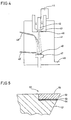
- Fig. 4 shows an apparatus for forming a diamond composite material which is applied to a cutting edge in manufacturing of a diamond cutting tool according to the present invention.
- the apparatus shown in Fig. 4 which is a DC arc plasma jet CVD apparatus employing a DC arc plasma jet for decomposing/activating a raw material gas, comprises a vacuum chamber 41 being exhaustible through an exhaust port 45, and a cathode 42 and an anode 43 provided therein for discharge.
- a power source 44 applies a dc voltage across the cathode 42 and the anode 43.
- a raw material gas for synthesizing diamond is supplied through the cathode 42 and the anode 43 as shown by arrows in Fig.
- the interior of the vacuum chamber 41 is maintained at a low pressure.
- the as-generated plasma strikes a surface of a substrate 48, which is provided in a direction of its movement and set on a cooling support 47, to grow diamond.
- fine powder of a metal or ceramics is supplied onto the substrate 48 through a nozzle 49 or 49' for supplying powder or fibers, so that a layer containing the metal or ceramics and the diamond in a mixed state is formed on the substrate surface.
- the support 47 is vibrated so that the powder or fibers homogeneously spread on the substrate surface, although such means is not shown in Fig. 4.
- Si substrates of 1 in. in diameter which were mirror-finished to be not more than 0.1 ⁇ m in surface roughness R max , were employed and scrached with diamond powder of #10000, so that diamond composite materials were formed thereon under conditions shown in Table 2 respectively.
- powder materials and fibers were supplied from the nozzle 49', so that the same were not melted by plasma jet flames.
- the Si substrates were dissolved and removed by fluoronitric acid, to obtain diamond composite materials respectively.
- the as-obtained diamond composite materials were cut with a laser into dimensions required for cutting edges, and thereafter Ti and Ni were successively stacked on crystal growth end planes in thicknesses of 1 ⁇ m and 2 ⁇ m respectively, so that the composite materials were vacuum-brazed to bases of cemented carbide (SPG 422) with a brazing filler metal, mainly composed of Cu, having a melting point of 1100°C through surfaces provided with such metallization layers serving as bonding planes respectively.
- Fig. 5 shows a principal part of each of the as-obtained diamond cutting tools.
- a cutting edge 52 of a diamond composite material is fixed to a prescribed region of a base 51 of cemented carbide through a metallization layer 53 and a brazing layer 54. While rake faces 55 of the diamond composite materials were not more than 0.2 ⁇ m in surface roughness R max in all such cutting tools, those exceeding 0.15 ⁇ m in surface roughness were slightly polished to be not more than 0.1 ⁇ m in R max .
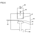
- Fig. 6 showing another apparatus for forming a diamond composite material which is applied to a cutting edge in manufacturing of the diamond cutting tool according to the present invention, is a conceptual diagram showing a thermal filament CVD apparatus employing a thermal filament heated to a high temperature for decomposing/activating a raw material gas.
- a filament 67 being formed by 10 W wires of 0.4 mm in diameter horizontally extended with tension at intervals of 4 mm, is provided in a vacuum chamber 66 which is exhaustible through an exhaust port 60. This filament 67 is heated to a prescribed temperature by a AC heating power source 68.
- a raw material gas is introduced into the vacuum chamber 66 through a gas supply nozzle 69.
- a substrate 62 which is fixed to a support 61 is provided immediately under the filament 67, so that diamond is grown on its surface. Simultaneously with growth of diamond, fine powder and fiber of a metal or ceramics or the like is supplied onto the substrate 62 through a nozzle 63, so that a composite layer containing the metal or ceramics and the diamond in a mixed state is formed on the substrate surface.
- a nozzle 63 Simultaneously with growth of diamond, fine powder and fiber of a metal or ceramics or the like is supplied onto the substrate 62 through a nozzle 63, so that a composite layer containing the metal or ceramics and the diamond in a mixed state is formed on the substrate surface.
- diamond composite materials were formed on Si substrates of 1 in. ⁇ which were mirror-finished to be not more than 0.1 ⁇ m in R max and scrached with diamond powder of #5000, and Mo substrates of 1 in. ⁇ which were similarly mirror-finished and scrached with diamond powder of #1000, under conditions shown in Table 3 respectively. Then, the Si substrates and the Mo substrates were dissolved and removed by a mixed solution of hydrofluoric acid and nitric acid and aqua regia respectively, to obtain diamond composite materials respectively. The as-obtained diamond composite materials were brazed to bases of cemented carbide in procedures similar to the above as cutting edges, and finally edged to complete cutting tools.
- the rake faces of the diamond composite materials were not more than 0.2 ⁇ m in surface roughness R max in all of those formed on the Si substrates, while those formed on Mo substrates included those having rake faces exceeding 0.2 ⁇ m in R max .
- the rake faces exceeding 0.15 ⁇ m in surface roughness were slightly polished to be not more than 0.1 ⁇ m in R max .
- Table 4 shows the results of the two types of cutting tests.
- Sample Cutting Test A Cutting Test B Flank Wear Width ( ⁇ m) Flank Wear Width ( ⁇ m) After Cutting for 5 min. After Cutting for 60 min. After Cutting for 5 min. After Cutting for 60 min. After Cutting for 60 min.
Landscapes
- Chemical & Material Sciences (AREA)
- Engineering & Computer Science (AREA)
- Mechanical Engineering (AREA)
- Chemical Kinetics & Catalysis (AREA)
- Materials Engineering (AREA)
- Metallurgy (AREA)
- Organic Chemistry (AREA)
- Inorganic Chemistry (AREA)
- General Chemical & Material Sciences (AREA)
- Physics & Mathematics (AREA)
- Plasma & Fusion (AREA)
- Cutting Tools, Boring Holders, And Turrets (AREA)
Claims (23)
- Diamantschneidwerkzeug mit einem Werkzeugsubstrat, das aus einem Werkzeugmaterial hergestellt ist, und einem Schneidkantenelement, das auf das Werkzeugsubstrat gelötet ist, wobei das Schneidkantenelement eine erste Schicht, die im wesentlichen aus dampfphasen-abgeschiedenem polykristallinem Diamant besteht und eine Kristallwachstumsstartoberfläche, die eine Fugenfläche des Schneidkantenelements definiert, sowie eine innere Oberfläche gegenüberliegend der Kristallwachstumsstartoberfläche aufweist, eine zweite Schicht, die auf der inneren Oberfläche der ersten Schicht gebildet ist und im wesentlichen aus dampfphasen-abgeschiedenem polykristallinem Diamant sowie einer Keramik und einem Metall besteht, wobei die Keramik und das Metall einen linearen Expansionskoeffizienten zwischen dem des Werkzeugmaterials und dem des polykristallinen Diamanten aufweisen, und eine dritte Schicht umfasst, die auf der zweiten Schicht gebildet ist und im wesentlichen aus dem Metall besteht, dadurch gekennzeichnet, dass das Schneidkantenelement auf das Werkzeugsubstrat über die dritte Schicht aufgelötet ist.
- Diamantschneidwerkzeug nach Anspruch 1, dadurch gekennzeichnet, dass das Schneidkantenelement eine gedrehte Form aufweist.
- Diamantschneidwerkzeug nach Anspruch 1, dadurch gekennzeichnet, dass das Metall ausgewählt ist aus der Gruppe bestehend aus Mo, W, Cr, V, Nb, Ta, Co, Ni und Fe, und dass die Keramik ausgewählt ist aus der Gruppe bestehend aus cBN, SiC, Si3N4, WC, BN, TiC, TaC, NbC, Cr3C2, MO2C, VC und TiN.
- Diamantschneidwerkzeug nach Anspruch 1, dadurch gekennzeichnet, dass die erste Schicht eine Dicke von mindestens 40 µm aufweist, dass die zweite Schicht eine Dicke im Bereich von 10 µm bis 300 µm aufweist und dass die dritte Schicht eine Dicke im Bereich von 50 µm bis 2000 µm aufweist.
- Diamantschneidwerkzeug nach Anspruch 1, dadurch gekennzeichnet, dass die Fugenfläche eine Oberflächenrauhigkeit Rmax von nicht mehr als 0,2 µm aufweist.
- Diamantschneidwerkzeug nach Anspruch 1, dadurch gekennzeichnet, dass das Werkzeugmaterial im wesentlichen aus einem Material besteht, das aus der Gruppe bestehend aus Superlegierungen, Sintercarbid und Hochgeschwindigkeitsstählen ausgewählt ist.
- Diamantschneidwerkzeug nach Anspruch 1, dadurch gekennzeichnet, dass das Werkzeugmaterial im wesentlichen aus Sintercarbid besteht, und dass das Metall ausgewählt ist aus der Gruppe bestehend aus Mo und W, und dass die Keramik ausgewählt ist aus der Gruppe bestehend aus SiC und Si3N4.
- Diamantschneidwerkzeug nach Anspruch 1, dadurch gekennzeichnet, dass das Schneidkantenelement eine Dicke im Bereich von 100 µm bis 1000 µm aufweist.
- Diamantschneidwerkzeug nach Anspruch 1, ferner umfassend eine Metallisierungsschicht, bestehend im wesentlichen aus einem Metall oder Halbmetallelement ausgebildet aus den Gruppen IIIb, IVa, IVb, Va, Vb, VIa, VIb, VIIa, und VIII gemäß der IUPAC-Version des Periodensystems sowie Legierungen und Verbindungen von diesen, bei welchem die Metallisierungsschicht zwischen der dritten Schicht und dem Werkzeugsubstrat zur Verbesserung der Lötverbindung des Schneidkantenelements auf dem Werkzeugsubstrat vorgesehen ist.
- Diamantschneidwerkzeug mit einem Werkzeugsubstrat aus Werkzeugmaterial und einem Schneidkantenelement, das an dem Werkzeugsubstrat befestigt ist, wobei das Schneidkantenelement eine Schneidkante und eine Fugenfläche aufweist sowie ein Verbundmaterial umfasst, das die Fugenfläche bildet, welches zumindest ein Zusatzmaterial ausgewählt aus der Gruppe bestehend aus Partikeln und Fasern umfasst, sowie ein Matrixmaterial, das das Zusatzmaterial bindet, bei welchem das Zusatzmaterial im wesentlichen aus zumindest einem Material besteht, ausgewählt aus der Gruppe bestehend aus Si, B, Ge, Übergangsmetallen der Gruppen IVa, Va, und VIa gemäß der IUPAC-Version des Periodensystems, Oxiden, Nitriden, Karbiden, Karbonitriden und Boriden aus B, Al, Si und Übergangsmetallen der Gruppen IVa, Va und VIa der IUPAC-Version des Periodensystems sowie Diamant, und bei welchem das Matrixmaterial im wesentlichen aus dampfphasen-abgeschiedenem polykristallinem Diamant besteht und bei welchem die Fugenfläche eine Kristallwachstumsstartoberfläche ist.
- Diamantschneidwerkzeug nach Anspruch 10, dadurch gekennzeichnet, dass das Zusatzmaterial Partikel aus kubischem BN umfasst und mindestens ein Teil der Partikel im wesentlichen gleichförmig in Bezug auf eine (111) Ebene des kubischen BN orientiert sind, und dass der polykristalline Diamant Diamantkristalle umfasst, die mit einer (111) Hauptkristallebene im wesentlichen parallel mit der Fugenfläche orientiert sind.
- Diamantschneidwerkzeug nach Anspruch 11, dadurch gekennzeichnet, dass die Diamantkristalle in einem Bereich, der sich von der Fugenfläche in eine Tiefe von zumindest 50 µm von der Fugenfläche erstreckt, in Bezug auf die Fugenfläche orientiert sind.
- Diamantschneidwerkzeug nach Anspruch 10, dadurch gekennzeichnet, dass das Zusatzmaterial im wesentlichen aus zumindest einem Material besteht, welches aus der Gruppe ausgewählt ist, die AlN, BN, B4C, SiC, Si3N4, TiC, TiN, Ti(CN), TiB2, MO2C, TaC, NbC, VC und WC besteht.
- Diamantschneidwerkzeug nach Anspruch 10, dadurch gekennzeichnet, dass das Zusatzmaterial Partikel umfasst, die einen Hauptdurchmesser in einem Bereich von 1 µm bis 50 µm aufweisen.
- Diamantschneidwerkzeug nach Anspruch 10, dadurch gekennzeichnet, dass das Zusatzmaterial Fasern umfasst, die einen Hauptdurchmesser in einem Bereich von 1 µm bis 50 µm aufweisen.
- Diamantschneidwerkzeug nach Anspruch 10, dadurch gekennzeichnet, dass das Verbundmaterial eine Dicke in einem Bereich von 200 µm bis 500 µm aufweist.
- Diamantschneidwerkzeug nach Anspruch 10, dadurch gekennzeichnet, dass das Schneidkantenelement resistent gegenüber einer chemischen Zersetzungsreaktion von Diamant zu nichtdiamantenem Kohlenstoff ist, und zwar während des Schneidens eines Eisenmaterials.
- Diamantschneidwerkzeug nach Anspruch 10, dadurch gekennzeichnet, dass das Verbundmaterial des Schneidkantenelements auf das Werkzeugsubstrat durch Löten aufgebracht ist.
- Diamantschneidwerkzeug nach Anspruch 10, dadurch gekennzeichnet, dass das Werkzeugmaterial im wesentlichen aus einem Material ausgewählt aus der Gruppe bestehend aus Superlegierungen, Sintercarbiden und Hochgeschwindigkeitsstählen besteht.
- Verfahren zur Herstellung eines Diamantschneidwerkzeugs mit einem Werkzeugssubstrat und einem Schneidkantenelement, das aus der Dampfphase abgeschiedenen po-Iykristallinen Diamanten beinhaltet und das auf das Werkzeugssubstrat gelötet ist, wobei das Verfahren die folgenden Schritte umfasst:a) Bilden einer Diamantschicht auf einem Basismaterial durch Dampfphasenabscheidung;b) Bilden einer Zwischenschicht auf der Diamantschicht, die in Schritt a) gebildet worden ist, durch Dampfphasenabscheidung von Diamant und einem Metall und einer Keramik, die beide eine linearen Ausdehnungskoeffizienten zwischen dem des Werkzeugsubstrats und zwischen dem des Diamanten aufweisen, und zwar durch Bereitstellung eines Pulvers von dem Metall und der Keramik während der Dampfphasenabscheidung des Schritts b);c) Bilden einer Nichtdiamantschicht durch Stoppen der Abscheidung des Diamanten und Abscheidung des Metalls;d) Entfernen des Basismaterials von der Diamantschicht, um das Schneidkantenelement mit einer Laminatstruktur einschließlich der Diamantschicht, der Zwischenschicht und der Nichtdiamantschicht, zu erhalten; unde) Auflöten des Schneidkantenelements auf das Werkzeugsubstrat, so dass eine Oberfläche der Diamantschicht, die in Kontakt mit dem Basismaterial gewesen ist, eine Fugenfläche definiert.
- Verfahren zur Herstellung eines Diamantschneidwerkzeugs, welches dampfphasenabgeschiedenen polykristallinen Diamant in einer Schneidkante eines Werkzeugs enthält, wobei das Verfahren die folgenden Schritte umfasst:a) Herstellung eines Basismaterials mit einer spiegelglatten Oberfläche;b) Abscheiden von Diamant auf der Oberfläche durch Dammphasenabscheidung während Partikel im wesentlichen bestehend aus zumindest einem Material ausgewählt aus der Gruppe bestehend aus Si, B, Ge, Übergangsmetallen der Gruppen IVa, Va und VIa der IUPAC-Version des Periodensystems, Oxiden, Nitriden, Karbiden, Carbonitriden und Boriden aus B, Al, Si und Übergangsmetallen der Gruppen IVa, Va und VIa der IUPAC-Version des Periodensystems und Diamant zugeführt werden,c) Entfernen des Basismaterials, um ein Diamantverbundmaterial zu erhalten, das im wesentlichen aus zumindest einem Material und Diamant besteht; undd) Auflöten des Diamantverbundmaterials auf ein Werkzeugsubstrat, so dass eine Oberfläche des Diamantverbundmaterials, das in Kontakt mit dem Basismaterial gewesen ist, eine Fugenfläche der Schneidkante definiert.
- Schneidwerkzeug nach Anspruch 1, dadurch gekennzeichnet, dass der lineare Ausdehnungskoeffizienten des Metalls und der Keramik näher an dem linearen Ausdehnungskoeffizienten des Werkzeugmaterials ist als dem des polykristallinen Diamanten.
- Verfahren nach Anspruch 20, dadurch gekennzeichnet, dass der lineare Ausdehnungskoeffizient des Metalls und der Keramik näher dem linearen Ausdehnungskoeffizienten des Materials des Werkzeugsubstrats als dem des Diamanten ist.
Applications Claiming Priority (6)
| Application Number | Priority Date | Filing Date | Title |
|---|---|---|---|
| JP17314392 | 1992-06-30 | ||
| JP17314392 | 1992-06-30 | ||
| JP173143/92 | 1992-06-30 | ||
| JP17672692 | 1992-07-03 | ||
| JP176726/92 | 1992-07-03 | ||
| JP17672692 | 1992-07-03 |
Publications (2)
| Publication Number | Publication Date |
|---|---|
| EP0577066A1 EP0577066A1 (de) | 1994-01-05 |
| EP0577066B1 true EP0577066B1 (de) | 2002-09-04 |
Family
ID=26495234
Family Applications (1)
| Application Number | Title | Priority Date | Filing Date |
|---|---|---|---|
| EP93110342A Expired - Lifetime EP0577066B1 (de) | 1992-06-30 | 1993-06-29 | Schneidwerkzeug unter Anwendung von aus der Dampfphase abgeschiedenem polykristallinem Diamant für die Schneidkante und Verfahren zu dessen Herstellung |
Country Status (3)
| Country | Link |
|---|---|
| US (1) | US5435815A (de) |
| EP (1) | EP0577066B1 (de) |
| DE (1) | DE69332263T2 (de) |
Cited By (1)
| Publication number | Priority date | Publication date | Assignee | Title |
|---|---|---|---|---|
| US9194189B2 (en) | 2011-09-19 | 2015-11-24 | Baker Hughes Incorporated | Methods of forming a cutting element for an earth-boring tool, a related cutting element, and an earth-boring tool including such a cutting element |
Families Citing this family (37)
| Publication number | Priority date | Publication date | Assignee | Title |
|---|---|---|---|---|
| US5976206A (en) * | 1995-05-19 | 1999-11-02 | Saint-Gobain/Norton Industrial Ceramics Corporation | Method of making white diamond film |
| US5722803A (en) * | 1995-07-14 | 1998-03-03 | Kennametal Inc. | Cutting tool and method of making the cutting tool |
| US5660936A (en) * | 1995-11-01 | 1997-08-26 | General Electric Company | Fine grain diamond tool and method of manufacture |
| US5858539A (en) * | 1995-12-22 | 1999-01-12 | Sandvik Ab | Diamond coated body and method of its production |
| EP0824605B1 (de) * | 1995-12-22 | 2002-07-17 | Sandvik Aktiebolag (publ) | Diamantbeschichteter körper und verfahren zu dessen herstellung |
| US5952102A (en) * | 1996-05-13 | 1999-09-14 | Ceramatec, Inc. | Diamond coated WC and WC-based composites with high apparent toughness |
| US5921856A (en) * | 1997-07-10 | 1999-07-13 | Sp3, Inc. | CVD diamond coated substrate for polishing pad conditioning head and method for making same |
| DE19859905C2 (de) * | 1998-01-27 | 2002-05-23 | Gfd Ges Fuer Diamantprodukte M | Diamantschneidwerkzeug |
| US6528159B1 (en) * | 1998-03-02 | 2003-03-04 | Sumitomo Electric Industries, Ltd. | Sintered diamond tool and method for manufacturing the same |
| KR100305315B1 (ko) | 1999-04-09 | 2001-09-13 | 박호군 | 다이아몬드 막이 코팅된 절삭공구 및 그 제조방법 |
| US6986208B1 (en) * | 1999-11-10 | 2006-01-17 | Bromer Nicholas S | Blade with microscopic ceramic cutting plates |
| DE19958474A1 (de) * | 1999-12-04 | 2001-06-21 | Bosch Gmbh Robert | Verfahren zur Erzeugung von Funktionsschichten mit einer Plasmastrahlquelle |
| DE19958473A1 (de) * | 1999-12-04 | 2001-06-07 | Bosch Gmbh Robert | Verfahren zur Herstellung von Kompositschichten mit einer Plasmastrahlquelle |
| UA74009C2 (en) * | 2000-09-20 | 2005-10-17 | Camco Int Uk Ltd | Polycrystalline diamond element |
| SE0301117L (sv) * | 2003-04-14 | 2004-10-15 | Skeleton Technologies Ag | Metod att tillverka en diamantkomposit |
| US20050025973A1 (en) * | 2003-07-25 | 2005-02-03 | Slutz David E. | CVD diamond-coated composite substrate containing a carbide-forming material and ceramic phases and method for making same |
| US20050249978A1 (en) | 2004-04-02 | 2005-11-10 | Xian Yao | Gradient polycrystalline cubic boron nitride materials and tools incorporating such materials |
| DE102004052068B4 (de) * | 2004-10-26 | 2008-04-03 | GFD-Gesellschaft für Diamantprodukte mbH | Schneidwerkzeug und dessen Verwendung |
| US9267332B2 (en) | 2006-11-30 | 2016-02-23 | Longyear Tm, Inc. | Impregnated drilling tools including elongated structures |
| US9540883B2 (en) | 2006-11-30 | 2017-01-10 | Longyear Tm, Inc. | Fiber-containing diamond-impregnated cutting tools and methods of forming and using same |
| US7695542B2 (en) * | 2006-11-30 | 2010-04-13 | Longyear Tm, Inc. | Fiber-containing diamond-impregnated cutting tools |
| US9468980B2 (en) * | 2007-04-03 | 2016-10-18 | H. Sam Cho | Contoured PCD and PCBN segments for cutting tools containing such segments |
| US8590646B2 (en) * | 2009-09-22 | 2013-11-26 | Longyear Tm, Inc. | Impregnated cutting elements with large abrasive cutting media and methods of making and using the same |
| KR20130059337A (ko) * | 2010-03-30 | 2013-06-05 | 아이엠알에이 아메리카, 인코포레이티드. | 레이저 기반 재료 가공 장치 및 방법들 |
| IE86959B1 (en) | 2010-11-29 | 2019-02-20 | Element Six Ltd | Fabrication of ultrafine polycrystalline diamond with nano-sized grain growth inhibitor |
| US8657894B2 (en) | 2011-04-15 | 2014-02-25 | Longyear Tm, Inc. | Use of resonant mixing to produce impregnated bits |
| EP2884865B1 (de) | 2012-08-20 | 2017-12-27 | Forever Mount, LLC | Lötverbindung zur befestigung von edelsteinen |
| GB201322837D0 (en) * | 2013-12-23 | 2014-02-12 | Element Six Ltd | Polycrystalline chemical vapour deposited diamond tool parts and methods of fabricating mounting and using the same |
| DE202014101175U1 (de) * | 2014-03-14 | 2014-03-24 | Axyn TeC Dünnschichttechnik GmbH | Materialverbund aus Metall / DLC / faserverstärktem Kunststoff |
| US11267102B2 (en) * | 2014-08-26 | 2022-03-08 | Nano Materials International Corporation | Aluminum diamond cutting tool |
| WO2016105340A1 (en) | 2014-12-22 | 2016-06-30 | Halliburton Energy Services, Inc. | Chemically strengthened bond between thermally stable polycrystalline hard materials and braze material |
| ES2865302T3 (es) | 2015-01-12 | 2021-10-15 | Longyear Tm Inc | Herramientas de perforación que tienen matrices con aleaciones con formación de carburos, y métodos de realización y utilización de las mismas |
| CA2975261C (en) * | 2015-03-10 | 2019-07-30 | Halliburton Energy Services, Inc. | Polycrystalline diamond compacts and methods of manufacture |
| CN113151751A (zh) * | 2021-04-25 | 2021-07-23 | 吉林大学 | 添加玄武岩纤维的金刚石热阻隔复合材料的制备方法 |
| CN113584478B (zh) * | 2021-08-03 | 2022-08-26 | 中国矿业大学 | 一种盾构机刀具表面自润滑硬质复合涂层的制备方法 |
| CN115652301B (zh) * | 2022-10-27 | 2024-08-20 | 邵阳市东昇超硬材料有限公司 | 一种复合型超硬材料及其制备方法 |
| CN119506754B (zh) * | 2024-11-21 | 2025-10-10 | 兰州理工大学 | 一种铁基非晶复合涂层及其制备方法和应用 |
Family Cites Families (9)
| Publication number | Priority date | Publication date | Assignee | Title |
|---|---|---|---|---|
| US3663191A (en) * | 1970-07-23 | 1972-05-16 | Dentsply Int Inc | Diamond tool and method of making the same |
| JPS5212126A (en) * | 1975-07-16 | 1977-01-29 | Hitachi Chem Co Ltd | Process for preparation of methacrylic acid |
| US4250210A (en) * | 1977-12-27 | 1981-02-10 | The International Nickel Co., Inc. | Chemical vapor deposition |
| DE3706340A1 (de) * | 1987-02-27 | 1988-09-08 | Winter & Sohn Ernst | Verfahren zum auftragen einer verschleissschutzschicht und danach hergestelltes erzeugnis |
| JPH01153228A (ja) * | 1987-12-10 | 1989-06-15 | Asahi Daiyamondo Kogyo Kk | 気相合成ダイヤモンド工具の製造法 |
| JPH01210201A (ja) * | 1988-02-16 | 1989-08-23 | Asahi Daiyamondo Kogyo Kk | 気相合成ダイヤモンド膜装着工具 |
| JP2607592B2 (ja) * | 1988-02-18 | 1997-05-07 | 住友電気工業株式会社 | 高耐摩耗性多結晶ダイヤモンド工具及びその製造方法 |
| JP2556393B2 (ja) * | 1990-02-07 | 1996-11-20 | ジーエヌツール株式会社 | ねじれ刃を有する切削工具及びその製造方法 |
| EP0469204B1 (de) * | 1990-08-03 | 1997-01-15 | Fujitsu Limited | Verfahren zur Abscheidung aus der Gasphase eines Diamantfilmes |
-
1993
- 1993-06-29 US US08/084,298 patent/US5435815A/en not_active Expired - Fee Related
- 1993-06-29 DE DE69332263T patent/DE69332263T2/de not_active Expired - Fee Related
- 1993-06-29 EP EP93110342A patent/EP0577066B1/de not_active Expired - Lifetime
Cited By (2)
| Publication number | Priority date | Publication date | Assignee | Title |
|---|---|---|---|---|
| US9194189B2 (en) | 2011-09-19 | 2015-11-24 | Baker Hughes Incorporated | Methods of forming a cutting element for an earth-boring tool, a related cutting element, and an earth-boring tool including such a cutting element |
| US9771497B2 (en) | 2011-09-19 | 2017-09-26 | Baker Hughes, A Ge Company, Llc | Methods of forming earth-boring tools |
Also Published As
| Publication number | Publication date |
|---|---|
| DE69332263D1 (de) | 2002-10-10 |
| DE69332263T2 (de) | 2003-08-07 |
| US5435815A (en) | 1995-07-25 |
| EP0577066A1 (de) | 1994-01-05 |
Similar Documents
| Publication | Publication Date | Title |
|---|---|---|
| EP0577066B1 (de) | Schneidwerkzeug unter Anwendung von aus der Dampfphase abgeschiedenem polykristallinem Diamant für die Schneidkante und Verfahren zu dessen Herstellung | |
| EP0541071B1 (de) | Schneidewerkzeug aus polykristallinen Diamanten und Verfahren zur Herstellung desselben | |
| EP0503822B2 (de) | Ein diamantbeschichteter und/oder mit diamantartigem Kohlenstoff beschichteter Hartstoff | |
| KR20000005021A (ko) | 붕소와 질소를 포함하는 초경 코팅을 갖는 기재와 그 제조방법 | |
| JP2949863B2 (ja) | 高靱性多結晶ダイヤモンドおよびその製造方法 | |
| US5607264A (en) | Tool with diamond cutting edge having vapor deposited metal oxide layer and a method of making and using such tool | |
| JP2867694B2 (ja) | 多結晶ダイヤモンド切削工具およびその製造方法 | |
| JPH06297206A (ja) | 硬質焼結体工具およびその製造方法 | |
| JPH0671503A (ja) | ダイヤモンド切削工具およびその製造方法 | |
| EP0560287A1 (de) | Diamantschneidwerkzeug und Verfahren zu seiner Herstellung | |
| KR102532558B1 (ko) | 고체 다이아몬드 재료의 코팅 방법 | |
| JPH04240007A (ja) | 多結晶ダイヤモンド切削工具およびその製造方法 | |
| US5567522A (en) | Diamond cutting tool and method of manufacturing the same | |
| JPH04261703A (ja) | 多結晶ダイヤモンド切削工具 | |
| JPH0679503A (ja) | 超硬質膜付工具及びその製造方法 | |
| JP3235206B2 (ja) | ダイヤモンド切削工具およびその製造方法 | |
| JPH07196379A (ja) | 気相合成ダイヤモンドろう付け工具およびその製造方法 | |
| JP2722649B2 (ja) | 切削用多結晶ダイヤモンド工具 | |
| JPH0516004A (ja) | 切削工具およびその製造方法 | |
| JPH08151297A (ja) | ダイヤモンドの製造方法 | |
| JPH05253757A (ja) | ダイヤモンド切削工具およびその製造方法 | |
| JP3134378B2 (ja) | ダイヤモンド被覆硬質材料 | |
| Bauer et al. | A comparative machining study of diamond-coated tools made by plasma torch, microwave, and hot filament techniques | |
| JPH0657426A (ja) | ダイヤモンド切削工具およびその製造方法 | |
| JP3033169B2 (ja) | ダイヤモンド被覆スローアウェイチップ及びその製造法 |
Legal Events
| Date | Code | Title | Description |
|---|---|---|---|
| PUAI | Public reference made under article 153(3) epc to a published international application that has entered the european phase |
Free format text: ORIGINAL CODE: 0009012 |
|
| AK | Designated contracting states |
Kind code of ref document: A1 Designated state(s): DE FR GB |
|
| 17P | Request for examination filed |
Effective date: 19940131 |
|
| 17Q | First examination report despatched |
Effective date: 19970128 |
|
| GRAG | Despatch of communication of intention to grant |
Free format text: ORIGINAL CODE: EPIDOS AGRA |
|
| GRAG | Despatch of communication of intention to grant |
Free format text: ORIGINAL CODE: EPIDOS AGRA |
|
| GRAH | Despatch of communication of intention to grant a patent |
Free format text: ORIGINAL CODE: EPIDOS IGRA |
|
| GRAH | Despatch of communication of intention to grant a patent |
Free format text: ORIGINAL CODE: EPIDOS IGRA |
|
| GRAA | (expected) grant |
Free format text: ORIGINAL CODE: 0009210 |
|
| AK | Designated contracting states |
Kind code of ref document: B1 Designated state(s): DE FR GB |
|
| PG25 | Lapsed in a contracting state [announced via postgrant information from national office to epo] |
Ref country code: FR Free format text: LAPSE BECAUSE OF NON-PAYMENT OF DUE FEES Effective date: 20020904 |
|
| REG | Reference to a national code |
Ref country code: GB Ref legal event code: FG4D |
|
| REF | Corresponds to: |
Ref document number: 69332263 Country of ref document: DE Date of ref document: 20021010 |
|
| EN | Fr: translation not filed | ||
| PGFP | Annual fee paid to national office [announced via postgrant information from national office to epo] |
Ref country code: GB Payment date: 20030625 Year of fee payment: 11 |
|
| PGFP | Annual fee paid to national office [announced via postgrant information from national office to epo] |
Ref country code: DE Payment date: 20030710 Year of fee payment: 11 |
|
| PLBE | No opposition filed within time limit |
Free format text: ORIGINAL CODE: 0009261 |
|
| STAA | Information on the status of an ep patent application or granted ep patent |
Free format text: STATUS: NO OPPOSITION FILED WITHIN TIME LIMIT |
|
| 26N | No opposition filed |
Effective date: 20030605 |
|
| PG25 | Lapsed in a contracting state [announced via postgrant information from national office to epo] |
Ref country code: GB Free format text: LAPSE BECAUSE OF NON-PAYMENT OF DUE FEES Effective date: 20040629 |
|
| PG25 | Lapsed in a contracting state [announced via postgrant information from national office to epo] |
Ref country code: DE Free format text: LAPSE BECAUSE OF NON-PAYMENT OF DUE FEES Effective date: 20050101 |
|
| GBPC | Gb: european patent ceased through non-payment of renewal fee |
Effective date: 20040629 |