EP0577220B1 - Dispositif de jeu comprenant une horloge à fonctionnement continu - Google Patents
Dispositif de jeu comprenant une horloge à fonctionnement continu Download PDFInfo
- Publication number
- EP0577220B1 EP0577220B1 EP93201908A EP93201908A EP0577220B1 EP 0577220 B1 EP0577220 B1 EP 0577220B1 EP 93201908 A EP93201908 A EP 93201908A EP 93201908 A EP93201908 A EP 93201908A EP 0577220 B1 EP0577220 B1 EP 0577220B1
- Authority
- EP
- European Patent Office
- Prior art keywords
- clock
- gaming device
- circuit
- monitoring
- data
- Prior art date
- Legal status (The legal status is an assumption and is not a legal conclusion. Google has not performed a legal analysis and makes no representation as to the accuracy of the status listed.)
- Expired - Lifetime
Links
Images
Classifications
-
- G—PHYSICS
- G06—COMPUTING OR CALCULATING; COUNTING
- G06F—ELECTRIC DIGITAL DATA PROCESSING
- G06F21/00—Security arrangements for protecting computers, components thereof, programs or data against unauthorised activity
- G06F21/70—Protecting specific internal or peripheral components, in which the protection of a component leads to protection of the entire computer
- G06F21/71—Protecting specific internal or peripheral components, in which the protection of a component leads to protection of the entire computer to assure secure computing or processing of information
- G06F21/72—Protecting specific internal or peripheral components, in which the protection of a component leads to protection of the entire computer to assure secure computing or processing of information in cryptographic circuits
- G06F21/725—Protecting specific internal or peripheral components, in which the protection of a component leads to protection of the entire computer to assure secure computing or processing of information in cryptographic circuits operating on a secure reference time value
-
- G—PHYSICS
- G04—HOROLOGY
- G04C—ELECTROMECHANICAL CLOCKS OR WATCHES
- G04C10/00—Arrangements of electric power supplies in time-pieces
- G04C10/04—Arrangements of electric power supplies in time-pieces with means for indicating the condition of the power supply
-
- G—PHYSICS
- G07—CHECKING-DEVICES
- G07C—TIME OR ATTENDANCE REGISTERS; REGISTERING OR INDICATING THE WORKING OF MACHINES; GENERATING RANDOM NUMBERS; VOTING OR LOTTERY APPARATUS; ARRANGEMENTS, SYSTEMS OR APPARATUS FOR CHECKING NOT PROVIDED FOR ELSEWHERE
- G07C1/00—Registering, indicating or recording the time of events or elapsed time, e.g. time-recorders for work people
-
- G—PHYSICS
- G07—CHECKING-DEVICES
- G07C—TIME OR ATTENDANCE REGISTERS; REGISTERING OR INDICATING THE WORKING OF MACHINES; GENERATING RANDOM NUMBERS; VOTING OR LOTTERY APPARATUS; ARRANGEMENTS, SYSTEMS OR APPARATUS FOR CHECKING NOT PROVIDED FOR ELSEWHERE
- G07C15/00—Generating random numbers; Lottery apparatus
- G07C15/006—Generating random numbers; Lottery apparatus electronically
-
- G—PHYSICS
- G07—CHECKING-DEVICES
- G07C—TIME OR ATTENDANCE REGISTERS; REGISTERING OR INDICATING THE WORKING OF MACHINES; GENERATING RANDOM NUMBERS; VOTING OR LOTTERY APPARATUS; ARRANGEMENTS, SYSTEMS OR APPARATUS FOR CHECKING NOT PROVIDED FOR ELSEWHERE
- G07C9/00—Individual registration on entry or exit
- G07C9/20—Individual registration on entry or exit involving the use of a pass
- G07C9/29—Individual registration on entry or exit involving the use of a pass the pass containing active electronic elements, e.g. smartcards
-
- G—PHYSICS
- G06—COMPUTING OR CALCULATING; COUNTING
- G06F—ELECTRIC DIGITAL DATA PROCESSING
- G06F2207/00—Indexing scheme relating to methods or arrangements for processing data by operating upon the order or content of the data handled
- G06F2207/72—Indexing scheme relating to groups G06F7/72 - G06F7/729
- G06F2207/7219—Countermeasures against side channel or fault attacks
Definitions
- Timing means or clock circuits, with continuous operation are well known. Certain new applications for such means impose new requirements, in particular in the field of games.
- the device described in United States patent No. 5,073,931 allows the recording of bets on sporting or other events which take place in front of the bettor. As this implies, most often financial consequences, the instant of the bet, which necessarily must take place before a fixed time limit, must not be able to be falsified. In particular, a player who cheats can try to allocate a time prior to the bet he makes, in fact, when he knows the outcome of the game.
- One of the aims of the invention is to provide a game device of the kind mentioned for which provision has been made countermeasures against these behaviors of fraudulent players.
- a device according to the invention is remarkable in that it further comprises protection means for physically counteracting falsification actions determined against said timing means, these protection means comprising means control to control in real time the conformity of the frequency of the timing signals with a range of frequencies of predetermined timing signals and of the first invalidation means dependent on the control means to provide persistent invalidation information to the inside said device in the event of non-compliance, due in particular to the decrease or increase in the frequency of timing signals, to invalidate said game device.
- Falsifying the timing means can consist in increasing or decreasing the clock frequency compared to its nominal value. If the timing means must measure a period of time between a bet time and a validation time, the person who cheats will try to increase the clock frequency during this time. If the timing means are not capable of measuring a time greater than said time, then the person who cheats will try to slow down the clock frequency during the time which separates the starting instant and the present instant from the bet.
- the English patent document No. 2,148,135 describes, more particularly page 8 in lines 43 to 53, the reinitialization of the content of a clock memory upon detection of an attempted fraud. This means that after such a reset, the fraudster can make other more elaborate attempts on the same circuit.
- the actions are blocked, while the reference invalidates only the results due to falsifications.
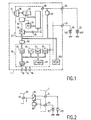
- Figure 1 shows a diagram of a device according to the invention.
- Figure 2 shows another embodiment of a device according to the invention.
- FIG. 1 shows a diagram of the device according to the invention.
- This device bears the reference 1. It essentially comprises an oscillator 10 which is controlled by a quartz 12 and a divider counter 15 forming a clock or timing circuit. These components may be part of an integrated circuit 20, commercially available under the reference PCF8583 and manufactured by Philips Electronics NV, Eindhoven, Netherlands.
- the contents of this divider counter 15 provide date information for a random access memory (RAM memory) 22 which is addressed by an addressing device 24.
- This output information is: the year, the month, the day, the hours , minutes, seconds, etc ...
- Other information can be contained in this memory: alarms, status information, etc ...
- the information contained in this memory can be read on a line 26 connected to his exit.
- An interface 30 allows communication of the I 2 C type to the outside of circuit 20.
- a logic member 32 makes it possible to control the entire operation of this circuit 20.
- This circuit 20 is supplied by a voltage applied to a terminal 33.
- an integrated safety circuit 50 is provided, in hybrid form or not, on the same substrate as the circuit 20.
- Integration prevents intervention from being carried out inside circuit 1. This integration can be accompanied by coating of the entire circuit, which makes any intrusion even more improbable.
- the safety circuit is for example constituted by a circuit of the kind registered under the number MC6805SC24.
- This circuit is formed by a microprocessor 55 to which are attached a RAM memory 57, a ROM memory 59 which contains the instructions for the operation of the microprocessor 55 and also an EEPROM memory 61 which can contain various data which cannot be erased by cutting off the power supply. .
- this circuit includes an access assembly 65 and 66, part of which 65 is assigned to communications inside circuit 1 and the other part 66 to communications to the outside.
- the circuit 1 is supplied by two voltage sources 70 and 72 via two supply terminals 73 and 74.
- the source 72 is designed to supply only the circuit 20.
- the circuit 1 is supplied by the same two voltage sources 70 and 72. But, preferably, it is the source 70 which supplies the circuits, even the circuit 20. If this source manifests a failure, this is detected by a supply voltage analyzer 80 (FIG. 2) which, in this case, controls a voltage switch 82 so that the circuit 20 is supplied by the voltage source 70.
- a supply voltage analyzer 80 FIG. 2 which, in this case, controls a voltage switch 82 so that the circuit 20 is supplied by the voltage source 70.
- the supply voltage of circuit 20 is interrupted, this is detected by another voltage analyzer 83 connected to the supply terminal 33.
- the voltage breakdown information can be reflected by the state of the data contained in the memory 22.
- the state of this supply voltage can also be analyzed by the circuit 50 by communicating to it the detection made by the analyzer 83 during its accesses I 2 C to the circuit 20.
- an interface circuit 90 has been provided.
- the program ensures communication on this bus, respecting the protocol defined by the measures relating to the I 2 C bus.
- the information concerning the timing circuit is made accessible via the circuit 50 on an access 92.
- the circuit 1 carries, in addition to the supply terminals 73 and 74, two other accesses 94 and 96 for, respectively, the re-initialization of the circuit and application of the clock signals necessary to the processor 55.
- the circuit 50 uses, according to a preferred operating mode, the DES encryption-decryption algorithm, as defined, for example, in the publication:
- EEPROM memory stores an encryption key C.
- the DAT date can be in clear, but it is accompanied by a DES code (C, DAT). So we can check the integrity of this DAT date, if of course C is known, every precaution being taken so that this key C remains unknown to any potential fraudster.
- This circuit is formed from a monostable circuit 100. During the duration T of switching of this circuit, the number of pulses of the oscillator 10 is counted. If the account is not suitable, a disability information can be prepared. Two pulses are derived from this circuit: one to signal the start of the duration T, the next for the end.
- the management of the monitoring can be executed by the microprocessor 55 under the supervision of a program contained in the ROM memory.
- a signal, passing through the interface 90, conveyed on the line I 2 C triggers the monostable 100 which delivers a pulse in the direction of the timing circuit 20.
- This pulse is accompanied by a command so that the time defined by the counter-divider 15 is recorded in the memory 22.
- the second pulse which causes the recording of a second content in the memory 22.
- the two contents are subtracted from each other and the result of the subtraction is compared with a standard value stored in the EEPROM memory. If the result of the subtraction is comparable, taking into account an acceptable precision, the timing circuit is considered to be intact, otherwise invalid information is stored in the EEPROM memory.
- the circuit of use of the timing circuit will be responsible for verifying the presence or absence of this no information validity to ensure the reliability of the values given by this circuit.
- the standard value contained in memory 61 is also obtained by difference. This calibration is necessary because the duration T can vary from one monostable circuit to another, but its precision is the same from one circuit to another.
- the invention also relates to any game box comprising this device.
- the box is connected, via an interface circuit, with a terminal to validate the bet data.
Landscapes
- Physics & Mathematics (AREA)
- General Physics & Mathematics (AREA)
- Engineering & Computer Science (AREA)
- Theoretical Computer Science (AREA)
- Computer Hardware Design (AREA)
- Software Systems (AREA)
- Computer Security & Cryptography (AREA)
- General Engineering & Computer Science (AREA)
- Mathematical Physics (AREA)
- Power Engineering (AREA)
- Storage Device Security (AREA)
- Electric Clocks (AREA)
- Pinball Game Machines (AREA)
Description
- La présente invention concerne un dispositif de jeu comprenant :
- des moyens de traitement d'informations dans lesquels sont prévus des moyens de mémorisation,
- des moyens d'entrée de données pour enregistrer des premières données de jeu dans lesdits moyens de mémorisation,
- des moyens de chronométrage pour fournir en permanence des états de chronométrage définis à partir de signaux de chronométrage, ayant des moyens d'accumulation d'états de chronométrage couplés avec lesdits moyens d'entrée de données pour entrer un état de chronométrage instantané associé avec lesdites premières données de jeu dans lesdits moyens de mémorisation, et
- des moyens de sortie pour sortir à un instant ultérieur lesdites données de jeu et l'état de chronométrage associé en tant que deuxièmes données d'entrée de jeu.
- Les moyens de chronométrage, ou circuits d'horloge, à fonctionnement continu sont bien connus. Certaines nouvelles applications pour de tels moyens imposent de nouvelles exigences, notamment dans le domaine des jeux. Le dispositif décrit dans le brevet des Etats-Unis d'Amérique n° 5 073 931 permet l'enregistrement de paris sur des événements sportifs ou autres qui se déroulent devant le parieur. Comme cela implique, le plus souvent des conséquences financières, l'instant du pari, qui nécessairement doit avoir lieu avant un temps limite déterminé, ne doit pas pouvoir être falsifié. En particulier, un joueur qui fraude peut essayer d'affecter un temps antérieur au pari qu'il effectue, en fait, au moment où il connaît l'issue du jeu.
- Un des buts de l'invention est de fournir un dispositif de jeu du genre mentionné pour lequel on a prévu des contremesures à l'encontre de ces comportements de joueurs fraudeurs. Pour atteindre ce but, un dispositif conforme à l'invention est remarquable en ce qu'il comprend en outre des moyens de protection pour contrecarrer physiquement des actions de falsification déterminées à l'encontre desdits moyens de chronométrage, ces moyens de protection comprenant des moyens de contrôle pour contrôler en temps réel la conformité de la fréquence des signaux de chronométrage avec une gamme de fréquences de signaux de chronométrage prédéterminée et des premiers moyens d'invalidation sous la dépendance des moyens de contrôle pour fournir une information d'invalidation persistante à l'intérieur dudit dispositif en cas de non-conformité, due notamment à la diminution ou à l'augmentation de la fréquence des signaux de chronométrage, pour invalider ledit dispositif de jeu.
- On remarquera que les mesures de l'invention sont efficaces et bon marché. Elles fournissent un obstacle pratiquement insurmontable aux agissements de joueurs fraudeurs.
- Falsifier les moyens de chronométrage peut consister à augmenter ou à diminuer la fréquence d'horloge par rapport à sa valeur nominale. Si les moyens de chronométrage doivent mesurer un laps de temps compris entre un temps de pari et un temps de validation, la personne qui fraude essaiera d'augmenter la fréquence d'horloge durant ce laps de temps. Si les moyens de chronométrage ne sont pas capables de mesurer un laps de temps supérieur audit laps de temps, alors la personne qui fraude essaiera de ralentir la fréquence d'horloge durant le temps qui sépare l'instant de départ et l'instant présent du pari. Le document de brevet anglais n° 2 148 135 décrit, plus spécialement page 8 aux lignes 43 à 53, la réinitialisation du contenu d'une mémoire d'horloge à la détection d'une tentative de fraude. Ceci signifie qu'après une telle réinitialisation le fraudeur peut entreprendre d'autres tentatives plus élaborées sur la même circuiterie.
- Selon la présente invention, les actions sont bloquées, tandis que la référence invalide uniquement les résultats dus aux falsifications.
- D'autres aspects avantageux de l'invention sont indiqués dans les revendications.
- La description suivante, accompagnée des dessins annexés, le tout donné à titre d'exemple non limitatif, fera bien comprendre comment l'invention peut être réalisée.
- La figure 1 montre un schéma d'un dispositif conforme à l'invention.
- La figure 2 montre un autre exemple de réalisation d'un dispositif conforme à l'invention.
- La figure 1 montre un schéma du dispositif conforme à l'invention. Ce dispositif porte la référence 1. Il comprend essentiellement un oscillateur 10 qui est piloté par un quartz 12 et un compteur diviseur 15 formant un circuit d'horloge ou de chronométrage. Ces composants peuvent être une partie d'un circuit intégré 20, disponible dans le commerce sous la référence PCF8583 et fabriqué par Philips Electronics N.V., Eindhoven, Pays-Bas. Les contenus de ce compteur diviseur 15 fournissent des informations de date pour une mémoire vive (mémoire RAM) 22 qui est adressée par un organe d'adressage 24. Ces informations de sortie sont : l'année, le mois, le jour, les heures, les minutes, les secondes, etc... D'autres informations peuvent être contenues dans cette mémoire : des informations d'alarmes, de statut, etc... Les informations contenues dans cette mémoire peuvent être lues sur une ligne 26 connectée à sa sortie. Une interface 30 permet une communication du genre I2C vers l'extérieur du circuit 20. Un organe de logique 32 permet de commander tout le fonctionnement de ce circuit 20. Ce circuit 20 est alimenté par une tension appliquée à une borne 33.
- Conformément à l'invention, pour éviter que les informations élaborées par ce circuit 20 soient falsifiées, on a prévu un circuit de sécurité 50 intégré, sous forme hybride ou non, sur le même substrat que le circuit 20.
- L'intégration évite qu'une intervention puisse s'effectuer à l'intérieur du circuit 1. Cette intégration peut s'accompagner d'un enrobage de tout le circuit, ce qui rend toute intrusion encore plus improbable.
- Le circuit de sécurité est par exemple constitué par un circuit du genre immatriculé sous le n° MC6805SC24. Ce circuit est formé d'un microprocesseur 55 auquel sont rattachées une mémoire RAM 57, une mémoire ROM 59 qui contient les instructions pour le fonctionnement du microprocesseur 55 et également une mémoire EEPROM 61 qui peut contenir différentes données non effaçables par coupure de l'alimentation.
- Ce circuit est très usité dans les cartes à puce du genre carte de crédit et son fonctionnement fait partie des connaisances générales. On pourra consulter à cet effet l'ouvrage :
- Pour communiquer, ce circuit comporte un ensemble d'accès 65 et 66 dont une partie 65 est affectée aux communications à l'intérieur du circuit 1 et l'autre partie 66 aux communications vers l'extérieur.
- Selon un premier mode de réalisation, le circuit 1 est alimenté par deux sources de tension 70 et 72 par l'intermédiaire de deux bornes d'alimentation 73 et 74. La source 72 est prévue pour alimenter uniquement le circuit 20.
- Selon un deuxième mode de réalisation montré à la figure 2, le circuit 1 est alimenté par les deux mêmes sources de tension 70 et 72. Mais, de préférence, c'est la source 70 qui alimente les circuits, même le circuit 20. Si cette source manifeste une défaillance, ceci est détecté par un analyseur de tension d'alimentation 80 (figure 2) qui, dans ce cas, commande un commutateur de tension 82 pour que le circuit 20 soit alimenté par la source de tension 70.
- L'importance de ces mesures est que l'on peut garantir une certaine autonomie de ce circuit de chronométrage (quelques années, compte tenu de sa faible consommation) alors que l'alimentation de l'environnement pour lequel il travaille peut nécessiter plusieurs changements de piles (source 70).
- Cependant, si la tension d'alimentation du circuit 20 vient à être interrompue, ceci est détecté par un autre analyseur de tension 83 connecté à la borne d'alimentation 33. L'information de rupture de tension peut être reflétée par l'état des données contenues dans la mémoire 22. L'état de cette tension d'alimentation peut également être analysé par le circuit 50 en lui communiquant la détection faite par l'analyseur 83 lors de ses accès I2C au circuit 20.
- Pour permettre une communication entre ce bus et le circuit de sécurité 50, un circuit d'interface 90 a été prévu. Le programme assure la communication sur ce bus en respectant le protocole défini par les mesures relatives au bus I2C.
- L'information concernant le circuit de chronométrage est rendue accessible via le circuit 50 sur un accès 92. Le circuit 1 porte, outre les bornes d'alimentation 73 et 74, deux autres accès 94 et 96 pour, respectivement, la re-initialisation du circuit et l'application des signaux d'horloge nécessaires au processeur 55.
- Le circuit 50 utilise, selon un mode de fonctionnement préférentiel, l'algorithme de cryptagedécryptage DES, tel que défini, par exemple, dans la publication :
- Dans la mémoire EEPROM, est enregistrée une clé de chiffrement C.
- Ainsi, à l'accès 92 la date DAT peut être en clair, mais elle est accompagnée d'un code DES (C, DAT). Ainsi, on peut vérifier l'intégrité de cette date DAT, si bien entendu on connaît C, toute précaution étant prise pour que cette clé C demeure inconnue à tout fraudeur potentiel.
- Il est possible de compliquer le processus en envoyant au circuit d'horloge 1 un aléa "a", de sorte que la date soit accompagnée d'un code DES (C, a, DAT).
- Pour éviter cela, conformément à l'invention, on a prévu un circuit de surveillance de la fréquence dudit oscillateur.
- Ce circuit est constitué à partir d'un circuit monostable 100. Pendant la durée T de basculement de ce circuit, le nombre d'impulsions de l'oscillateur 10 est compté. Si le compte n'est pas convenable, une information d'invalidité peut être élaborée. On dérive de ce circuit deux impulsions : une pour signaler le début de la durée T, la suivante pour la fin.
- La gestion de la surveillance peut être exécutée par le microprocesseur 55 sous la conduite d'un programme contenu dans la mémoire ROM.
- Ainsi à un instant donné, un signal, transitant par l'interface 90, véhiculé sur la ligne I2C déclenche le monostable 100 qui délivre une impulsion en direction du circuit de chronométrage 20. Cette impulsion est accompagnée d'une commande pour que le temps défini par le compteur-diviseur 15 soit enregistré dans la mémoire 22. Puis après un laps de temps T survient la deuxième impulsion, ce qui provoque l'enregistrement d'un deuxième contenu dans la mémoire 22. Ensuite, les deux contenus sont soustraits l'un de l'autre et le résultat de la soustraction est comparé à une valeur étalon emmagasinée dans la mémoire EEPROM. Si le résultat de la soustraction est comparable, compte tenu d'une précision acceptable, le circuit de chronométrage est considéré comme intact, sinon une information de non validité est emmagasinée dans la mémoire EEPROM. Le circuit d'utilisation du circuit de chronométrage aura à charge de vérifier la présence ou l'absence de cette information de non validité pour s'assurer de la fiabilité des valeurs données par ce circuit.
- La valeur étalon contenue dans la mémoire 61 est obtenue aussi par différence. Cet étalonnage est nécessaire car la durée T peut varier d'un circuit monostable à l'autre, mais sa précision est la même d'un circuit à l'autre.
- L'invention concerne aussi tout boîtier de jeu comprenant ce dispositif. Le boîtier est mis en relation, via un circuit d'interface, avec un terminal pour valider les données du pari.
Claims (7)
- Dispositif de jeu comprenant :- des moyens de traitement d'informations (50) dans lesquels sont prévus des moyens de mémorisation,- des moyens d'entrée de données (90, 66) pour enregistrer des premières données de jeu dans lesdits moyens de mémorisation,- des moyens de chronométrage (20) pour fournir en permanence des états de chronométrage définis à partir de signaux de chronométrage, ayant des moyens d'accumulation d'états de chronométrage couplés avec lesdits moyens d'entrée de données pour entrer un état de chronométrage instantané associé avec lesdites premières données de jeu dans lesdits moyens de mémorisation, et- des moyens de sortie (66) pour sortir à un instant ultérieur lesdites données de jeu et l'état de chronométrage associé en tant que deuxièmes données d'entrée de jeu,
dispositif caractérisé en ce qu'il comprend en outre :- des moyens de protection (50) pour contrecarrer physiquement des actions de falsification déterminées à l'encontre desdits moyens de chronométrage, ces moyens de protection comprenant des moyens de contrôle (100...) pour contrôler en temps réel la conformité de la fréquence des signaux de chronométrage avec une gamme de fréquences de signaux de chronométrage prédéterminée et des premiers moyens d'invalidation (50) sous la dépendance des moyens de contrôle (100...) pour fournir une information d'invalidation persistante à l'intérieur dudit dispositif en cas de non-conformité due, notamment à la diminution ou à l'augmentation de la fréquence d'horloge, pour invalider ledit dispositif de jeu. - Dispositif de jeu selon la revendication 1, caractérisé en ce que lesdits moyens de protection comprennent en outre des moyens de blocage (50) pour bloquer tout accès depuis lesdits moyens d'entrée vers les moyens d'accumulation, par lesquels les changements externes de l'état de chronométrage sont évités.
- Dispositif de jeu selon la revendication 1 ou 2, caractérisé en ce que lesdits moyens de protection impliquent des moyens d'encapsulation pour que les moyens de chronométrage (20) et les moyens d'accumulation d'états soient mis dans la même capsule.
- Dispositif de jeu selon l'une des revendications 1 à 3, caractérisé en ce que lesdits moyens de protection comprennent des seconds moyens de contrôle (83) pour contrôler la conformité du voltage et/ou du courant de la source d'alimentation et des seconds moyens d'invalidation sous la dépendance des seconds moyens de contrôle pour fournir une information supplémentaire d'invalidation permanente à l'intérieur dudit dispositif de jeu lors de la détection d'une non-conformité, par lesquels l'augmentation ou la diminution externe de ladite fréquence d'horloge, en conséquence d'une variation de ladite tention et/ou du courant, invalide le dispositif de jeu.
- Dispositif de jeu selon la revendication 4, caractérisé en ce qu'il est prévu, en plus de la première source d'alimentation (70) pour les moyens de chronométrage, au moins une deuxième source de tension (72) pour d'autres moyens.
- Dispositif de jeu selon la revendication 4 ou 5, caractérisé en ce qu'il est prévu au moins une source d'alimentation de secours pour les moyens de chronométrage mise en service par lesdits seconds moyens de contrôle.
- Boîtier de jeu contenant un dispositif selon la revendication 1 à 6 et ayant des moyens d'interface pour communiquer avec un dispositif de terminal.
Applications Claiming Priority (4)
| Application Number | Priority Date | Filing Date | Title |
|---|---|---|---|
| FR9208099 | 1992-07-01 | ||
| FR9208100A FR2693296B1 (fr) | 1992-07-01 | 1992-07-01 | Circuit d'horloge pour dispositif de jeu. |
| FR9208099A FR2693295B1 (fr) | 1992-07-01 | 1992-07-01 | Circuit d'horloge pour dispositif de jeu. |
| FR9208100 | 1992-07-01 |
Publications (2)
| Publication Number | Publication Date |
|---|---|
| EP0577220A1 EP0577220A1 (fr) | 1994-01-05 |
| EP0577220B1 true EP0577220B1 (fr) | 1997-04-23 |
Family
ID=26229561
Family Applications (1)
| Application Number | Title | Priority Date | Filing Date |
|---|---|---|---|
| EP93201908A Expired - Lifetime EP0577220B1 (fr) | 1992-07-01 | 1993-07-01 | Dispositif de jeu comprenant une horloge à fonctionnement continu |
Country Status (4)
| Country | Link |
|---|---|
| US (1) | US5489095A (fr) |
| EP (1) | EP0577220B1 (fr) |
| JP (1) | JP3577328B2 (fr) |
| DE (1) | DE69310034T2 (fr) |
Families Citing this family (33)
| Publication number | Priority date | Publication date | Assignee | Title |
|---|---|---|---|---|
| US5643086A (en) * | 1995-06-29 | 1997-07-01 | Silicon Gaming, Inc. | Electronic casino gaming apparatus with improved play capacity, authentication and security |
| US7063615B2 (en) * | 1995-06-29 | 2006-06-20 | Igt | Electronic gaming apparatus with authentication |
| US6620047B1 (en) | 1995-06-29 | 2003-09-16 | Igt | Electronic gaming apparatus having authentication data sets |
| USRE39369E1 (en) | 1995-06-29 | 2006-10-31 | Igt | Electronic casino gaming system with improved play capacity, authentication and security |
| AU4635696A (en) * | 1995-11-30 | 1997-06-19 | Garri Kimovich Kasparov | Method of playing a lottery game and suitable system |
| US6071190A (en) * | 1997-05-21 | 2000-06-06 | Casino Data Systems | Gaming device security system: apparatus and method |
| US20020025852A1 (en) * | 2000-09-29 | 2002-02-28 | Alcorn Allan E. | Gaming apparatus with portrait-mode display |
| AUPP734298A0 (en) * | 1998-11-26 | 1998-12-24 | Aristocrat Leisure Industries Pty Ltd | Electronic casino gaming with authentication and improved security |
| US20050255924A1 (en) * | 2000-03-03 | 2005-11-17 | Cole Joseph W | Gaming apparatus having door mounted display |
| CA2402389A1 (fr) * | 2000-03-08 | 2002-09-19 | Shuffle Master, Inc. | Systeme de jeu informatise, procede d'utilisation et appareil |
| US7043641B1 (en) | 2000-03-08 | 2006-05-09 | Igt | Encryption in a secure computerized gaming system |
| US7988559B2 (en) * | 2001-03-08 | 2011-08-02 | Igt | Computerized gaming system, method and apparatus |
| AU8512501A (en) * | 2000-08-21 | 2002-03-04 | Int Game Tech | Method and apparatus for software authentication |
| CA2356015A1 (fr) | 2000-08-31 | 2002-02-28 | International Game Technology | Methode et appareil de codage de bons d'echange dans un systeme de jeux de casino sans numeraire |
| US7203841B2 (en) * | 2001-03-08 | 2007-04-10 | Igt | Encryption in a secure computerized gaming system |
| EP1258807A3 (fr) * | 2001-05-14 | 2005-11-02 | Matsushita Electric Industrial Co., Ltd. | Dispositif de surveillance d'accès illégal, carte à puce et procédé de surveillance d'accès illégal |
| US7162036B2 (en) | 2001-08-06 | 2007-01-09 | Igt | Digital identification of unique game characteristics |
| US6685567B2 (en) * | 2001-08-08 | 2004-02-03 | Igt | Process verification |
| US7618317B2 (en) * | 2001-09-10 | 2009-11-17 | Jackson Mark D | Method for developing gaming programs compatible with a computerized gaming operating system and apparatus |
| US7931533B2 (en) * | 2001-09-28 | 2011-04-26 | Igt | Game development architecture that decouples the game logic from the graphics logics |
| US6902481B2 (en) * | 2001-09-28 | 2005-06-07 | Igt | Decoupling of the graphical presentation of a game from the presentation logic |
| US20030064784A1 (en) * | 2001-09-28 | 2003-04-03 | William Wells | Wide screen gaming apparatus |
| US8708828B2 (en) * | 2001-09-28 | 2014-04-29 | Igt | Pluggable modular gaming modifiers and configuration templates for gaming environments |
| US7179170B2 (en) * | 2001-11-26 | 2007-02-20 | Igt | Pass-through live validation device and method |
| US6962530B2 (en) | 2002-04-25 | 2005-11-08 | Igt | Authentication in a secure computerized gaming system |
| US7076802B2 (en) * | 2002-12-31 | 2006-07-11 | Intel Corporation | Trusted system clock |
| US20040128528A1 (en) * | 2002-12-31 | 2004-07-01 | Poisner David I. | Trusted real time clock |
| CA2857208C (fr) | 2003-05-30 | 2018-09-04 | Privaris, Inc. | Systeme de securite en-circuit et procedes de commande d'acces a et d'utilisation de donnees sensibles |
| US7794323B2 (en) * | 2003-07-25 | 2010-09-14 | Igt | Gaming apparatus with encryption and method |
| US8327448B2 (en) * | 2005-06-22 | 2012-12-04 | Intel Corporation | Protected clock management based upon a non-trusted persistent time source |
| JP5351664B2 (ja) * | 2009-09-02 | 2013-11-27 | 株式会社コナミデジタルエンタテインメント | ゲーム装置、ゲーム制御方法、及び、プログラム |
| RU2417812C1 (ru) * | 2010-06-21 | 2011-05-10 | Валерий Филиппович Иванов | Способ и система для проведения интерактивных игр |
| US8627097B2 (en) | 2012-03-27 | 2014-01-07 | Igt | System and method enabling parallel processing of hash functions using authentication checkpoint hashes |
Family Cites Families (16)
| Publication number | Priority date | Publication date | Assignee | Title |
|---|---|---|---|---|
| SE381940B (sv) * | 1972-04-11 | 1975-12-22 | Gretag Ag | Anordning for enskild identifiering av ett flertal individer |
| US4047114A (en) * | 1976-08-06 | 1977-09-06 | The United States Of America As Represented By The Secretary Of The Army | Digital detector |
| US4068180A (en) * | 1976-10-22 | 1978-01-10 | Schlumberger Technology Corporation | Methods and apparatus for enhancing resolution in pulse analysis |
| CH640971A5 (en) * | 1979-06-28 | 1984-01-31 | Kurt Ehrat | Mobile data container secured against unauthorised access |
| US4365810A (en) * | 1979-09-28 | 1982-12-28 | Selectro-Vision, Ltd. | Gaming board |
| GB2148135A (en) * | 1983-09-14 | 1985-05-30 | Igt Reno Nev | Electronic video lottery system |
| US4575621A (en) * | 1984-03-07 | 1986-03-11 | Corpra Research, Inc. | Portable electronic transaction device and system therefor |
| US4592546A (en) * | 1984-04-26 | 1986-06-03 | David B. Lockton | Game of skill playable by remote participants in conjunction with a live event |
| GB2189059B (en) * | 1986-04-08 | 1989-11-22 | Distrimex Limited | Clock with power-failure alarm |
| GB2228805A (en) * | 1989-03-01 | 1990-09-05 | Screening Consultants Limited | Crystal oscillator-controlled clocks |
| FR2658375B2 (fr) * | 1989-05-25 | 1994-04-22 | Adventure | Dispositif electronique destine a permettre la participation d'un individu a un programme telediffuse. |
| US5347579A (en) * | 1989-07-05 | 1994-09-13 | Blandford Robert R | Personal computer diary |
| GB8920940D0 (en) * | 1989-09-15 | 1989-11-01 | Ncr Co | Portable container for valuable items |
| US5089770A (en) * | 1990-02-20 | 1992-02-18 | Lunayach Communications Consultants | Frequency measuring system |
| US5168372A (en) * | 1990-11-29 | 1992-12-01 | Sweetser David J | Video control system |
| US5150407A (en) * | 1991-12-16 | 1992-09-22 | Chan Steve S C | Secured data storage devices |
-
1993
- 1993-06-23 US US08/082,074 patent/US5489095A/en not_active Expired - Lifetime
- 1993-06-28 JP JP15694593A patent/JP3577328B2/ja not_active Expired - Fee Related
- 1993-07-01 EP EP93201908A patent/EP0577220B1/fr not_active Expired - Lifetime
- 1993-07-01 DE DE69310034T patent/DE69310034T2/de not_active Expired - Fee Related
Also Published As
| Publication number | Publication date |
|---|---|
| US5489095A (en) | 1996-02-06 |
| JPH06187067A (ja) | 1994-07-08 |
| EP0577220A1 (fr) | 1994-01-05 |
| DE69310034D1 (de) | 1997-05-28 |
| JP3577328B2 (ja) | 2004-10-13 |
| DE69310034T2 (de) | 1997-10-30 |
Similar Documents
| Publication | Publication Date | Title |
|---|---|---|
| EP0577220B1 (fr) | Dispositif de jeu comprenant une horloge à fonctionnement continu | |
| EP0252812B1 (fr) | Dispositif de sécurité interdisant le fonctionnement d'un ensemble électronique après une première coupure de son alimentation électrique | |
| EP0423035B1 (fr) | Système de paiement ou de transfert d'informations par carte à mémoire électronique porte-monnaie | |
| CA1300757C (fr) | Dispositif portable electronique destine a etre utilise en liaison avec un ecran | |
| FR2654236A1 (fr) | Procede de protection contre l'utilisation frauduleuse de cartes a microprocesseur, et dispositif de mise en óoeuvre. | |
| EP1055203B1 (fr) | Protocole de controle d'acces entre une cle et une serrure electronique | |
| FR2843466A1 (fr) | Procede pour empecher la falsification d'un systeme de traitement de donnees, et ce systeme | |
| EP0943134B1 (fr) | Systeme de gestion des transferts d'unites de valeur | |
| EP0742532A1 (fr) | Procédé de mémoration et de restitution d'un code secret | |
| EP3469446B1 (fr) | Procédé de calibration d'une horloge d'un circuit de carte à puce, et système associé | |
| EP1108249B1 (fr) | Procede de securisation du traitement d'une information sensible dans un module de securite monolithique, et module de securite associe | |
| FR2731288A1 (fr) | Machine a jouer, notamment machine a sous | |
| FR2637710A1 (fr) | Procede et dispositif de commande electronique multifonction a haute securite comportant une carte a puce | |
| EP0891587A1 (fr) | Procede de securisation d'un module de securite, et module de securite associe | |
| FR2693296A1 (fr) | Circuit d'horloge pour dispositif de jeu. | |
| FR2693295A1 (fr) | Circuit d'horloge pour dispositif de jeu. | |
| FR2999751A1 (fr) | Procede de protection d’un terminal electronique, programme d'ordinateur, et terminal electronique correspondants. | |
| EP0481880B1 (fr) | Procédé de télésurveillance à gestion simplifiée | |
| FR3052895A1 (fr) | Procede d'envoi d'une information de securite | |
| FR2522850A2 (fr) | Systeme de controle par exemple pour le passage de points de peage | |
| EP0922272A1 (fr) | Systeme de gestion des transferts d'unites de valeurs dans un systeme de jeu a cartes a puce | |
| FR2711263A1 (fr) | Dispositif électronique de certification horodatée. | |
| EP0585513B1 (fr) | Système de contrÔle de processus avec table de simultanéités | |
| CH691011A5 (fr) | Dispositif de chronométrage électronique. | |
| EP3690685A1 (fr) | Procede d'authentification d'un utilisateur et dispositif associe |
Legal Events
| Date | Code | Title | Description |
|---|---|---|---|
| PUAI | Public reference made under article 153(3) epc to a published international application that has entered the european phase |
Free format text: ORIGINAL CODE: 0009012 |
|
| AK | Designated contracting states |
Kind code of ref document: A1 Designated state(s): DE FR GB |
|
| RAP1 | Party data changed (applicant data changed or rights of an application transferred) |
Owner name: N.V. PHILIPS' GLOEILAMPENFABRIEKEN Owner name: TRT TELECOMMUNICATIONS RADIOELECTRIQUES ET TELEPHO |
|
| 17P | Request for examination filed |
Effective date: 19940620 |
|
| 17Q | First examination report despatched |
Effective date: 19950727 |
|
| RAP1 | Party data changed (applicant data changed or rights of an application transferred) |
Owner name: PHILIPS ELECTRONICS N.V. Owner name: PHILIPS CARTES ET SYSTEMES |
|
| GRAG | Despatch of communication of intention to grant |
Free format text: ORIGINAL CODE: EPIDOS AGRA |
|
| GRAH | Despatch of communication of intention to grant a patent |
Free format text: ORIGINAL CODE: EPIDOS IGRA |
|
| GRAH | Despatch of communication of intention to grant a patent |
Free format text: ORIGINAL CODE: EPIDOS IGRA |
|
| GRAA | (expected) grant |
Free format text: ORIGINAL CODE: 0009210 |
|
| AK | Designated contracting states |
Kind code of ref document: B1 Designated state(s): DE FR GB |
|
| REF | Corresponds to: |
Ref document number: 69310034 Country of ref document: DE Date of ref document: 19970528 |
|
| GBT | Gb: translation of ep patent filed (gb section 77(6)(a)/1977) |
Effective date: 19970710 |
|
| REG | Reference to a national code |
Ref country code: FR Ref legal event code: TP |
|
| PLBE | No opposition filed within time limit |
Free format text: ORIGINAL CODE: 0009261 |
|
| STAA | Information on the status of an ep patent application or granted ep patent |
Free format text: STATUS: NO OPPOSITION FILED WITHIN TIME LIMIT |
|
| 26N | No opposition filed | ||
| REG | Reference to a national code |
Ref country code: FR Ref legal event code: CD |
|
| REG | Reference to a national code |
Ref country code: GB Ref legal event code: IF02 |
|
| REG | Reference to a national code |
Ref country code: FR Ref legal event code: D6 |
|
| REG | Reference to a national code |
Ref country code: GB Ref legal event code: 746 Effective date: 20021205 |
|
| PGFP | Annual fee paid to national office [announced via postgrant information from national office to epo] |
Ref country code: DE Payment date: 20080904 Year of fee payment: 16 |
|
| PGFP | Annual fee paid to national office [announced via postgrant information from national office to epo] |
Ref country code: FR Payment date: 20080729 Year of fee payment: 16 |
|
| PGFP | Annual fee paid to national office [announced via postgrant information from national office to epo] |
Ref country code: GB Payment date: 20080828 Year of fee payment: 16 |
|
| GBPC | Gb: european patent ceased through non-payment of renewal fee |
Effective date: 20090701 |
|
| REG | Reference to a national code |
Ref country code: FR Ref legal event code: ST Effective date: 20100331 |
|
| PG25 | Lapsed in a contracting state [announced via postgrant information from national office to epo] |
Ref country code: FR Free format text: LAPSE BECAUSE OF NON-PAYMENT OF DUE FEES Effective date: 20090731 |
|
| PG25 | Lapsed in a contracting state [announced via postgrant information from national office to epo] |
Ref country code: GB Free format text: LAPSE BECAUSE OF NON-PAYMENT OF DUE FEES Effective date: 20090701 |
|
| PG25 | Lapsed in a contracting state [announced via postgrant information from national office to epo] |
Ref country code: DE Free format text: LAPSE BECAUSE OF NON-PAYMENT OF DUE FEES Effective date: 20100202 |