EP0577261A2 - Source infrarouge à haut rendement - Google Patents
Source infrarouge à haut rendement Download PDFInfo
- Publication number
- EP0577261A2 EP0577261A2 EP93303995A EP93303995A EP0577261A2 EP 0577261 A2 EP0577261 A2 EP 0577261A2 EP 93303995 A EP93303995 A EP 93303995A EP 93303995 A EP93303995 A EP 93303995A EP 0577261 A2 EP0577261 A2 EP 0577261A2
- Authority
- EP
- European Patent Office
- Prior art keywords
- housing
- infrared
- insulator core
- window
- source
- Prior art date
- Legal status (The legal status is an assumption and is not a legal conclusion. Google has not performed a legal analysis and makes no representation as to the accuracy of the status listed.)
- Withdrawn
Links
Images


Classifications
-
- H—ELECTRICITY
- H01—ELECTRIC ELEMENTS
- H01K—ELECTRIC INCANDESCENT LAMPS
- H01K13/00—Lamps having an incandescent body which is substantially non-conductive until heated, e.g. Nernst lamp
-
- G—PHYSICS
- G01—MEASURING; TESTING
- G01J—MEASUREMENT OF INTENSITY, VELOCITY, SPECTRAL CONTENT, POLARISATION, PHASE OR PULSE CHARACTERISTICS OF INFRARED, VISIBLE OR ULTRAVIOLET LIGHT; COLORIMETRY; RADIATION PYROMETRY
- G01J3/00—Spectrometry; Spectrophotometry; Monochromators; Measuring colours
- G01J3/02—Details
- G01J3/10—Arrangements of light sources specially adapted for spectrometry or colorimetry
- G01J3/108—Arrangements of light sources specially adapted for spectrometry or colorimetry for measurement in the infrared range
-
- H—ELECTRICITY
- H01—ELECTRIC ELEMENTS
- H01K—ELECTRIC INCANDESCENT LAMPS
- H01K1/00—Details
- H01K1/28—Envelopes; Vessels
Definitions
- This invention pertains generally to the field of light sources, particularly those emitting in the infrared wavelengths, and more particularly to infrared sources used in analytical instruments such as infrared spectrometers.
- Infrared spectrometers such as Fourier transform infrared (FTIR) spectrometers, dispersive-type infrared spectrometers and filter-based infrared spectrometers, are widely used for measuring the chemical composition and characteristics of materials.
- FTIR Fourier transform infrared
- dispersive-type infrared spectrometers and filter-based infrared spectrometers
- filter-based infrared spectrometers are widely used for measuring the chemical composition and characteristics of materials.
- infrared radiation provided by a source having a relatively broad emission bandwidth is passed through a spectrometer, and then through a sample, before reaching a suitable detector.
- the information obtained from the detected radiation is analyzed to determine information concerning the sample, for example to determine an absorbance spectrum of the sample in the infrared range. This spectrum may then be used to identify the chemical composition of the sample.
- the infrared source for an infrared spectrometer have a relatively broad and uniform emission spectrum over the wavelengths of interest.
- conventional broadband infrared sources that meet these criteria typically possess several undesirable characteristics, including relatively high power consumption and the production of relatively high levels of stray infrared radiation, e.g., radiation that travels in unwanted directions. These characteristics are undesirable because they produce a substantial amount of wasted energy and an unwanted heating of the parts of the spectrometer.
- any stray infrared from the source may interfere with the signal reaching the infrared detector, and therefore the detector must be carefully shielded from the source.
- Even if a conventional infrared source is surrounded by heat insulation, the insulation itself tends to increase in temperature and will eventually itself become a source of heat which is transmitted either by conduction, convection or reemission of infrared radiation to other parts of the spectrometer.
- conventional infrared sources have been both a heat load on the spectrometer and also a significant power drain which adds to the total power requirements of the spectrometer.
- an infrared source commonly used in spectrometry is the "glow bar,” which is a coil of silicon carbide that is resistively heated to a temperature of about 1200 degrees Celsius. Due to the relatively large size of the coil, this type of source is relatively costly and inefficient. For instance, the glow bar consumes about 150 watts of power, which requires a relatively large power supply, and usually one that is separate from the power supply for the electronic components in the spectrometer. The combination of glow bar and power supply adds cost, weight and size to the spectrometer. The glow bar also radiates a lot of heat -- more heat than can be passively dissipated inside a modern spectrometer.
- the glow bar is typically cooled with water flowing through a water jacket that surrounds the source.
- Water cooling adds plumbing and water supply requirements, which adds further cost, weight, size and complexity to the spectrometer. Manufacturing and field service are also more difficult, since the water jacket can interfere with access to the source.
- Infrared spectrometers for special purposes may sometimes be used in environments where the spectrometer may be exposed to corrosive gases.
- the hot source element commonly operating at about 1200° Celsius
- Infrared spectrometers often use a purge gas such as dry air or nitrogen to pressurize the spectrometer to reduce corrosion caused by ambient gases that might react with the source electrode.
- gases for example Freon-113, that will react with the hot source electrode or hot exposed parts to produce very corrosive chemicals.
- Freon-113 gases that will react with the hot source electrode or hot exposed parts to produce very corrosive chemicals.
- Freon-113 when exposed to a 1200° C source, can produce a small but significant quantity of various acids, including hydrochloric acid and hydrofluoric acid. These acids corrode the source electrode and can also condense on the cooler components in the interferometer, for example, the fasteners, flex pivots, and electrical connectors. Purge gas failures can thus result in damage to the spectrometer.
- the infrared source in accordance with the present invention is highly efficient in energy consumption, provides an exit beam of infrared radiation which can be readily collected and focused into a well defined beam, produces relatively little infrared radiation in directions other than that of the intended exit beam, and may be sealed to minimize contact between corrosive ambient gases and the infrared element of the source.
- the source is relatively compact and lightweight, since no reflecting elements are needed to capture the infrared emitted from the infrared element.
- the source is highly efficient in converting electrical energy to infrared energy, which is primarily emitted only into the exit beam which can be fully collected and focused, and provides an output infrared beam having a beam power equivalent to a conventional source while consuming far less electrical power.
- the infrared source of the invention has an insulator core having an outlet port formed preferably as a fairly narrow channel which opens from the core to define the outlet (and, if desired, the optical aperture) for the infrared beam.
- An electrical resistive heating infrared element is supported within a containment cavity in the insulator core to face the outlet port so that infrared from the element passing through the outlet port will define the exit beam from the source.
- the infrared element is otherwise surrounded by the insulator core material.
- an aperture insert member which defines the optical aperture may be mounted between the window and the infrared element.
- the insert may be formed of metal machined to provide a well defined aperture.
- the insulator core is formed so as to yield high thermal efficiency for the source.
- the insulator core is formed of ceramic fiber material (e.g., zirconia fiber board) which has extremely good resistance to high temperatures as well as very low thermal conductivity.
- ceramic fiber material e.g., zirconia fiber board
- Such material can be formed so that the walls of the containment cavity are very close to the infrared element, and thus exposed to extreme heat, without damage to the insulator.
- heat from the infrared element will not be substantially transmitted through the core to any surrounding material, but rather will be primarily concentrated in the volume of the insulator core adjacent the containment cavity and also in the air within the containment cavity surrounding the element. The only significant outlet for the heat is through the outlet port.
- the heating element can be maintained at a temperature appropriate for radiating the desired infrared wavelengths with low consumption of electrical power. In this manner, very high efficiency of conversion of electrical input power to infrared output power in the exit beam is obtained.
- the conversion is so efficient that the standard low voltage power supply of the spectrometer may generally be used to supply the source, thus avoiding the need for a separate infrared source power supply of the type which is typically required for conventional sources.
- the infrared element and core may be mounted within a housing having an infrared window which is sealed to the housing to inhibit the flow of corrosive gases into the interior of the housing.
- the housing is preferably formed of a solid body of metal, such as aluminum, which has good thermal conductivity.
- the solid housing body also preferably provides good thermal mass to allow rapid conduction of heat away from any hot spots through the mass of the body to the external surfaces of the housing where the heat can be either radiated or lost by conduction to the ambient air.
- the housing temperature is thereby maintained at a relatively low temperature, which may reduce the likelihood of injury to persons or property in the event of accidental contact with the housing.
- the insulator core is preferably mounted in a central cavity within the housing body to be surrounded by the metal of the housing except where an outlet opening is provided in the housing which is covered by the window.
- the infrared element is part of an infrared element support unit which includes a cap, a plug which extends into the housing and into the insulator core, and the infrared element which mounts on the end of the plug.
- the plug fits into an opening in the housing such that the walls of the plug and the cap are closely spaced to the walls of the housing.
- a sealing ring positioned between the plug and cap and the housing when the unit is assembled seals the interior of the housing from the ambient.
- a window assembly is fitted to the outlet opening in the housing body and is tightly engaged to the housing body with a sealing ring to prevent passage of gases into the housing.
- the window assembly itself includes a frame unit which threads into the housing, an infrared transmissive window which is sealed against a seal ring on the inside of the frame unit, and a holding plug which holds the window tightly in place to provide a tight seal between the window and the window frame.
- the window itself is formed of an infrared transmissive material such as potassium bromide, quartz, and other materials which are relatively transmissive to infrared.
- the window is preferably of a thickness so that it is relatively strong and impervious to migration of gases from the ambient to the interior of the housing.
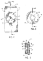
- the source 10 includes a housing body 11 formed of metal (e.g., aluminum), having a front face 13 and a window assembly 12 extending from the front face.
- a top closure plate 14 is secured to the top of the housing body 11 by screws 16 and has a central opening through which electrical supply lines 15 pass which are connected to the infrared element within the source 11, as described further below.
- openings 17 are shown formed in the housing 11 at positions adjacent the edges of the plate 14 and extend entirely through the body of the housing 11 from top to bottom. These holes may be utilized to mount the infrared source in a desired position within a spectrometer (not shown) using mounting bolts (not shown).
- the housing body 11 has an outlet opening 18 formed in its front, extending inwardly from its front face 13, which is threaded to engage threads formed on the window assembly, as described further below.
- An insulator core 19 is mounted within a central cavity defined by walls 20 within the housing body 11.
- the insulator core 19 includes a raised circular face 21 at its outer surface, a centrally formed outlet port 22, and a conical bevel 23 formed between the port 22 and the face 21.
- the window assembly 12 is shown in more detail in a front view in Fig. 3 and in a cross-sectional view in Fig. 5.
- the assembly 12 includes a window 24 which is exposed by an opening 25 in a window frame 26.
- the frame 26 has a rearward ring extension 27 on which is formed outer threads 28 and inner threads 29.
- the outer threads 28 engage with the threads formed on the bore 18 of the housing body.
- the window 24, which may be formed of various infrared transmissive materials such as potassium bromide (KBr) which may have a coating (e.g., barium fluoride coating), quartz, and the like, is securely held in place against the frame by a holding plug 31 having an interior bore 32.
- KBr potassium bromide
- the plug 31 has outer threads that engage against the internal threads 29 to allow the plug to be screwed into place against the window 24 and to press the window against a seal ring 34 located between the interior surface of the window frame 26 and the window 24.
- a seal ring 34 located between the interior surface of the window frame 26 and the window 24.
- An O-ring seal 35 mounts around the ring extension 27 within a channel formed in a back surface of the window frame 26 and is compressed down tightly against the front face 13 of the housing body when the window assembly 12 is screwed into the threads formed in the outlet opening 18 in the housing 11.
- FIG. 4 A cross-section through the housing 11 with the window assembly removed is shown in Fig. 4.
- the insulator core 19 has a containment cavity 38 which is in communication with the outlet port 22, and a somewhat larger cavity 39 near the top of the insulator core.
- An infrared element support unit 40 is mounted to the housing so that an electrical infrared heating element 41 of the unit 40 extends down into the containment cavity 38 so that a portion of the element 41 is exposed to the outlet port 22.
- the walls of the containment cavity 38 are sized so that they are closely spaced from the infrared element 41 to provide a minimum volume of air that is heated by the element within the containment cavity.
- the element 41 is supported at the end of a plug 42 which extends down to the bottom of the expanded cavity 39 and is adjacent to or in contact with the bottom of the cavity 39.
- the plug 42 also extends partially through an opening 46 provided in the housing 11 having walls which are closely spaced to the outer walls of the plug 42.
- the plug 42 extends up to and is preferably integrally formed with an expanded cap portion 43 which fits within an expanded opening 47 at the very top of the housing body 11.
- a central bore through the cap 43 and the plug 42 of the unit 40 admits the electrical wires 15 which are connected to the element 41.
- This bore is preferably filled and sealed with a high temperature resistant ceramic cement material 44 (e.g., Sauereisen Electrotemp #8 cement) and may be topped off with a gas barrier such as epoxy (e.g., Stycast 2662 epoxy encapsulant or, preferably, Oxy-Cast 6057LDLS epoxy casting resin from Resin Technology Group, Inc.).
- An O-ring gasket 49 fits within a chamfer formed around the opening 46 and is pressed down by the bottom of the cap 43 when the top plate 14 is screwed down tightly onto the top of the housing 11 and pressed down onto the cap 43. In this manner, a tight seal is formed by the gasket 49 to prevent gases from entering into the containment cavity 38.
- the O-ring gasket 49 (and other gaskets used in the source) is preferably formed of chemical resistant elastomer. Suitable gaskets are ChemrazTM elastomeric PTFE O-rings from Greene, Tweed.
- the element 41 may be a flattened electrical resistance heating element formed in a generally U-shape.
- the heater element 41 provides a very narrow source of infrared radiation, whereas when oriented as shown in Fig. 6 to the port 22, a broader but still concentrated source of infrared radiation is presented.
- the particular construction and materials of the heater element 41 are not crucial, and standard electrical resistance heater elements may be utilized which emit in the appropriate wavelengths, such as those commercially used for ignition plugs for furnaces and the like. Examples are ignitors produced by Norton Industrial Ceramics which are made of silicon carbide, including model No. 301-T for 10 volt operation and Model No. 401-T for 15 volt operation.
- the insulator core 19 is shown in more detail in Fig. 8 removed from the interior of the housing.
- the core has substantially cylindrical top and bottom surfaces 50 and flat side surfaces 51.
- a correspondingly shaped central cavity within the main housing 11 is also formed having the general shape of the top and bottom surfaces 50 and the side surfaces 51 so that the insulator core 19 can be pressed tightly and firmly into position within the main housing through the front outlet 18.
- the side walls 20 of the central cavity within the housing engage the side walls 51 to hold the core firmly in place.
- the core 19 is preferably formed of a ceramic fiber type material, e.g., Zircar Products, Inc. fiber ceramic SALI and, preferably, type ZYZ3 zirconia insulating board composed of yttria stabilized zirconia fibers processed and bonded with zircon.
- the insulator core may receive a colloidal silica surface treatment. This material has very good insulating properties while being an excellent refractory material, and is able to withstand very high temperatures (up to 1650°C) without deterioration.
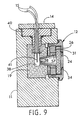
- FIG. 9 A cross-sectional view through a modified embodiment of the infrared source of the invention is shown in Fig. 9.
- an aperture defining insert 57 is mounted to fit within the inner bore of the holding plug 31 and has a conical shaped inner surface which extends down to an opening 58 adjacent to the infrared element 41.
- the opening 58 defines, with the inner surfaces of the insert 57, the optical aperture of the source.
- the insert 57 can be formed of a ceramic or metal material, allowing close tolerance machining of the surfaces to provide a precisely defined aperture.
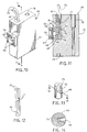
- FIG. 10 A further embodiment of an infrared source in accordance with the invention is shown generally at 60 in Fig. 10 in partial perspective view.
- the source 60 has a housing body 61, formed of metal such as aluminum or other heat conductive material, and has a window assembly 62 mounted on the front face thereof.
- An insulator core 63 shown in cross-section in Fig. 11, is mounted within a central cavity 69 in the housing body 61.
- the window assembly 62 is attached to the housing body 61 by screws 64 which thread through the window assembly into threaded holes in the housing body to tightly press an infrared transmissive window 65 against a sealing ring 66 which surrounds an outlet opening 67 in the housing body adjacent to the insulator core 63.
- This sealing ring thus provides an air-tight seal against gases reaching the heating element 70 which is mounted within a containment cavity 73 in the insulator core 63.
- An outlet port 68 in the insulator core 63 exposes a portion of the infrared element 70 to the outlet opening 67 to allow infrared radiated from the element to pass through the window 65.
- the outlet port 68 combined with the outlet opening 67 and the conical opening in the window assembly, defines the optical aperture for the source.
- the source 60 may also have a window assembly which screws into a threaded bore in the housing body, if desired, with sealing O-rings between the window assembly and the window and between the window and the housing body to seal off the interior of the housing from the atmosphere.
- the infrared element 70 may be formed as a U-shaped heating element such as silicon carbide, as described above, which is electrically connected to conductors 71, e.g., formed of copper, which form part of supply wires 72 which extend to a power supply (not shown).
- conductors 71 e.g., formed of copper
- the infrared element 70 extends into the containment cavity of the insulator core 73, but a portion of it also extends upwardly beyond the insulator core.
- a high temperature ceramic material 74 for example, a Sauereisen No.
- a layer of air impervious sealant 76 (for example, epoxy) is preferably formed to provide an airtight seal to prevent gases from entering into the containment cavity 73 of the insulator core and contacting the element 70.
- a bore 78 is formed entirely through the housing body 61 at a position spaced away from the insulator core, and a hole 79 is formed at the bottom of the housing body preferably directly under the infrared element 70.
- the source may be mounted in place in a spectrometer which has a peg which fits into the hole 79 by providing a bolt which passes through the hole 78 and threads into a threaded hole in a spectrometer mounting plate (not shown) to secure the source into a desired position within the spectrometer.
- the infrared source 60 is formed so that the infared element 70 is generally permanently embedded within the housing 61.
- the source 60 is expected to be relatively easy and inexpensive to replace.
- the source 60 is expected to have a relatively long life since the infrared element 70 is expected to be substantially sealed from the outside atmosphere by the window assembly 62, and should deteriorate relatively slowly over time.
- Other measures to extend the life of the infrared element 70 for example backfilling the interior of the source with a noble gas, such as argon or xenon, and/or adding a desiccant to absorb water vapor that may outgas from the insulator core 63, may also be used.
- the infrared element 70 is inserted within the containment cavity 73 in close spacing to the walls of the cavity.
- substantially all of the element 70 is in contact with the insulator core material to minimize air-space about the element.
- the element 70 is preferably out of contact with the walls of the containment cavity only at the outlet port 68.
- the material of the insulator core 63 is again preferably formed as described above for the insulator core 19, preferably comprising a fiber ceramic material with high resistance to temperature and very low thermal conductivity.
- the infrared source 60 is thus substantially entirely sealed from the outside ambient so that potentially corrosive gases will not readily reach the heating element, and any corrosive gases formed at the heating element will not readily escape from the interior of the housing.
- FIG. 15 A cross-sectional view through a preferred embodiment of a source 80 in accordance with the invention is shown in Fig. 15.
- the source 80 includes certain of the features of the source shown in Fig. 9 and the source of Figs. 10 and 11.
- the source 80 has a metal housing 81 formed of a metal such as aluminum and a window assembly 82 substantially identical to the window assembly 12.
- the window assembly 82 includes a frame 83, an infrared transmissive window 85, an O-ring seal 86 between the window 85 and the frame 83, an O-ring seal 87 between the frame 83 and the front face of the housing 81, and a holding plug and aperture member 89 which threads into the interior bore of the frame 83 to press the window 85 tightly against the seal 86.
- the window frame 83 may be formed of a high temperature plastic, e.g., Ertalyte® crystalline PET thermoplastic polyester from ERTA.
- the member 89 has an aperture defining conical wall 90 which has an open inner end 91, defining the optical aperture of the source, which is located at a position very close to the bottom end of the infrared element 93 within an insulator core 94.
- the member 89 may be formed of a metal, such as stainless steel, which can be machined to form the aperture.
- the aperture member 89 is shown in direct contact with the window 85 in Fig. 15.
- a compliant spacer such as an O-ring gasket, may be placed between the window 85 and the aperture member 89 to compensate for any variations in window thickness to maintain a nearly constant aperture spacing and hold the window firmly in place.
- the aperture member 89 may have various structures, and could form part of the window assembly to thread into the housing body.
- the inner end 91 of the insert 90 extends into the insulator core 94 to terminate at a position closely adjacent to, but preferably out of contact with, the heating element 93.
- the opening 91 combined with the inner walls of the insert 90 precisely define the optical aperture of the source.
- the element 93 is in contact with the insulator core except at the aperture opening 91 to minimize heat loss from the element.
- the infrared element 93 is preferably mounted in a containment cavity 95 within the insulator core 94.
- the containment cavity has walls which are very closely spaced to, and preferably in contact with, the infrared element 93.
- the insulator core 94 is preferably formed of the fiber ceramic material as described above. This material is relatively soft and can be penetrated by a hard material such as the solid infrared element 93.
- One manner of forming the containment cavity 95 within the core 94 is by pressing the element 93 into a solid block forming the insulator core 94 until the infrared element 93 extends downwardly to the desired termination point within the insulator core 94 at the apex of a cone shaped hole formed in the core which receives the conical wall 90.
- the infrared element forms its own containment cavity and the walls of the containment cavity are essentially in contact with the infrared element except at the aperture defining opening 91 which is also the outlet port of the insulator core, absolutely minimizing the air space around the heating element within the insulator core.
- the containment cavity may alternatively be preformed, such as by milling, to dimensions which closely fit to the infrared element.
- the infrared heating element 93 is formed so that only the bottom end of the heating element at the position adjacent to the opening 91 attains the maximum heating temperature, and the material of the insulator core 94 is capable of withstanding the temperatures of the heating element 93 which is in contact therewith.
- the insulating core 94 is formed as part of a replaceable source element unit 96.
- the unit 96 includes a substantially cylindrical body 97 which extends into a corresponding well within the housing 81, and a top plate 98 which may be integrally formed with the body 97.
- the insulating core 94 is mounted within a central cavity within the body 97, and an opening 98 is formed in the walls of the body 97 at a position facing the window assembly to allow the conical wall 90 to pass therethrough when the window assembly 82 is screwed into the housing 81.
- the heating element 93 is secured in the unit 96 in a manner similar to that described above for the source 60, in that a ceramic sealant material 102 is filled in a cavity above the insulating core 94 to surround and embed a portion of the heating element which extends above the core 94, as well as the portions of the wires 99 from the electrical supply lines 100 which connect to the element 93.
- An epoxy sealant 103 seals up the top of the opening around the wires 99 to prevent gases from the ambient to come into contact with the infrared element 93.
- a sealing O-ring 105 mounted in a chamfer in the housing 81 surrounds the opening in the housing through which the body 96 passes and provides an air tight seal when the top plate 98 is secured to the housing by screws (not shown) which thread through screw openings 106 in the plate 98. Openings 108 at the bottom of the housing 81 facilitate the mounting and proper placement of the source within a spectrometer.
- the sharply defined opening 91 of the insert 90 is formed just adjacent to the hot part of the infrared element 93 to define the aperture therefrom, a very sharply defined aperture is obtained in the source 80.
Landscapes
- Physics & Mathematics (AREA)
- Spectroscopy & Molecular Physics (AREA)
- General Physics & Mathematics (AREA)
- Investigating Or Analysing Materials By Optical Means (AREA)
Applications Claiming Priority (2)
| Application Number | Priority Date | Filing Date | Title |
|---|---|---|---|
| US907127 | 1992-07-01 | ||
| US07/907,127 US5291022A (en) | 1992-07-01 | 1992-07-01 | High efficiency infrared source |
Publications (2)
| Publication Number | Publication Date |
|---|---|
| EP0577261A2 true EP0577261A2 (fr) | 1994-01-05 |
| EP0577261A3 EP0577261A3 (en) | 1994-06-01 |
Family
ID=25423567
Family Applications (1)
| Application Number | Title | Priority Date | Filing Date |
|---|---|---|---|
| EP19930303995 Withdrawn EP0577261A3 (en) | 1992-07-01 | 1993-05-24 | High efficiency infrared source |
Country Status (2)
| Country | Link |
|---|---|
| US (1) | US5291022A (fr) |
| EP (1) | EP0577261A3 (fr) |
Cited By (3)
| Publication number | Priority date | Publication date | Assignee | Title |
|---|---|---|---|---|
| EP0692702A1 (fr) * | 1994-07-11 | 1996-01-17 | Instrumentarium Corporation | Source d'infrarouge pour analyseur de gaz et procédé de génération de rayonnement infrarouge |
| WO2003037178A3 (fr) * | 2001-10-29 | 2003-06-05 | Optiscan Biomedical Corp | Ensemble fenetre |
| DE10318786A1 (de) * | 2003-04-25 | 2004-11-25 | Nattkemper, Andreas, Dipl.-Ing. | FTIR-Messzelle zur Analyse aggressiver Gase |
Families Citing this family (7)
| Publication number | Priority date | Publication date | Assignee | Title |
|---|---|---|---|---|
| US5406090A (en) * | 1993-02-22 | 1995-04-11 | Mattson Instruments, Inc. | Spectrometer and IR source therefor |
| US5910659A (en) * | 1996-04-30 | 1999-06-08 | The United States Of America As Represented By The Secretary Of Commerce | Flat panel thermal infrared generator |
| US6633771B1 (en) * | 1999-03-10 | 2003-10-14 | Optiscan Biomedical Corporation | Solid-state non-invasive thermal cycling spectrometer |
| US6198949B1 (en) * | 1999-03-10 | 2001-03-06 | Optiscan Biomedical Corporation | Solid-state non-invasive infrared absorption spectrometer for the generation and capture of thermal gradient spectra from living tissue |
| US7119904B2 (en) * | 2004-01-13 | 2006-10-10 | Thermo Electron Scientific Instruments Corporation | Stabilized infrared source for infrared spectrometers |
| US8975604B2 (en) * | 2009-09-18 | 2015-03-10 | Thermo Electron Scientific Instruments Llc | Emissivity enhanced mid IR source |
| TWM493394U (zh) * | 2014-08-14 | 2015-01-11 | Univ Nat Taiwan | 紅外線發射器 |
Family Cites Families (8)
| Publication number | Priority date | Publication date | Assignee | Title |
|---|---|---|---|---|
| US3225224A (en) * | 1962-10-22 | 1965-12-21 | Gen Electric | Distribution transformer lighting assembly |
| BE790954A (fr) * | 1971-12-23 | 1973-05-03 | Schlumberger Compteurs | Emetteur de rayonnement infrarouge |
| JPS5754825A (en) * | 1980-09-19 | 1982-04-01 | Yamatake Honeywell Co Ltd | Light source apparatus for infrared ray analyzer |
| US4467213A (en) * | 1982-06-28 | 1984-08-21 | Beckman Instruments, Inc. | Source assembly for gas analysis instruments |
| US4499382A (en) * | 1982-10-18 | 1985-02-12 | Hewlett-Packard Company | Infrared source element |
| US4912329A (en) * | 1987-03-30 | 1990-03-27 | The Foxboro Company | Portable battery-operated ambient air analyzer |
| US4935633A (en) * | 1988-10-11 | 1990-06-19 | Bio-Rad Laboratories, Inc. | Low power infrared source assembly for spectrometer |
| NO170366C (no) * | 1989-05-26 | 1997-02-10 | Kanstad Teknologi As | Pulserende infraröd strålingskilde |
-
1992
- 1992-07-01 US US07/907,127 patent/US5291022A/en not_active Expired - Lifetime
-
1993
- 1993-05-24 EP EP19930303995 patent/EP0577261A3/en not_active Withdrawn
Cited By (4)
| Publication number | Priority date | Publication date | Assignee | Title |
|---|---|---|---|---|
| EP0692702A1 (fr) * | 1994-07-11 | 1996-01-17 | Instrumentarium Corporation | Source d'infrarouge pour analyseur de gaz et procédé de génération de rayonnement infrarouge |
| WO2003037178A3 (fr) * | 2001-10-29 | 2003-06-05 | Optiscan Biomedical Corp | Ensemble fenetre |
| DE10318786A1 (de) * | 2003-04-25 | 2004-11-25 | Nattkemper, Andreas, Dipl.-Ing. | FTIR-Messzelle zur Analyse aggressiver Gase |
| DE10318786B4 (de) * | 2003-04-25 | 2006-03-09 | Nattkemper, Andreas, Dr.-Ing. | FTIR-Messzelle zur Analyse aggressiver Gase |
Also Published As
| Publication number | Publication date |
|---|---|
| US5291022A (en) | 1994-03-01 |
| EP0577261A3 (en) | 1994-06-01 |
Similar Documents
| Publication | Publication Date | Title |
|---|---|---|
| US5291022A (en) | High efficiency infrared source | |
| US6964501B2 (en) | Peltier-cooled LED lighting assembly | |
| JP3671951B2 (ja) | 測温装置及びそれを用いたセラミックスヒータ | |
| US6172452B1 (en) | Low pressure mercury vapor discharge lamp with heat conductive component | |
| US20030178943A1 (en) | Microwave energized plasma lamp with solid dielectric waveguide | |
| US6818885B2 (en) | Photodetector | |
| KR20040038753A (ko) | 성막용 장치 | |
| KR100616727B1 (ko) | 포터블형 광원 장치 | |
| US9057488B2 (en) | Liquid-cooled LED lamp | |
| US6325535B1 (en) | In-situ radiant heat flux probe cooled by suction of ambient air | |
| US4965484A (en) | Vapor discharge lamp with gradient temperature control | |
| US9939366B2 (en) | Spectrometer insert for measuring temperature-dependent optical properties | |
| US5235184A (en) | Highly stable low noise CCD spectrograph | |
| EP1802963A1 (fr) | Dispositif et procede de mesure de la concentration d'hydrogene dans des metaux fondus | |
| US11965825B2 (en) | In-line compact measuring device | |
| US20040245482A1 (en) | High heat radiating structure of gas sensor | |
| JP3042229B2 (ja) | 基板加熱装置 | |
| KR100715584B1 (ko) | 포터블형 광원 장치 | |
| CN100588297C (zh) | 辐射装置 | |
| US4308008A (en) | Method for differential thermal analysis | |
| CN211318208U (zh) | 气体分析仪 | |
| US5747820A (en) | Infrared radiation source for a gas analyzer and method for generating infrared radiation | |
| JP4249350B2 (ja) | ランプハウス及び光源装置 | |
| US5044753A (en) | Environmentally sealed colorimeter for industrial environments | |
| JP4249351B2 (ja) | 光源装置 |
Legal Events
| Date | Code | Title | Description |
|---|---|---|---|
| PUAI | Public reference made under article 153(3) epc to a published international application that has entered the european phase |
Free format text: ORIGINAL CODE: 0009012 |
|
| AK | Designated contracting states |
Kind code of ref document: A2 Designated state(s): DE FR GB |
|
| PUAL | Search report despatched |
Free format text: ORIGINAL CODE: 0009013 |
|
| AK | Designated contracting states |
Kind code of ref document: A3 Designated state(s): DE FR GB |
|
| STAA | Information on the status of an ep patent application or granted ep patent |
Free format text: STATUS: THE APPLICATION IS DEEMED TO BE WITHDRAWN |
|
| 18D | Application deemed to be withdrawn |
Effective date: 19941202 |