EP0577310A2 - Dispositif de traitement d'image - Google Patents
Dispositif de traitement d'image Download PDFInfo
- Publication number
- EP0577310A2 EP0577310A2 EP93304848A EP93304848A EP0577310A2 EP 0577310 A2 EP0577310 A2 EP 0577310A2 EP 93304848 A EP93304848 A EP 93304848A EP 93304848 A EP93304848 A EP 93304848A EP 0577310 A2 EP0577310 A2 EP 0577310A2
- Authority
- EP
- European Patent Office
- Prior art keywords
- codes
- circuit
- motion
- code
- encoding
- Prior art date
- Legal status (The legal status is an assumption and is not a legal conclusion. Google has not performed a legal analysis and makes no representation as to the accuracy of the status listed.)
- Granted
Links
Images








Classifications
-
- H—ELECTRICITY
- H04—ELECTRIC COMMUNICATION TECHNIQUE
- H04N—PICTORIAL COMMUNICATION, e.g. TELEVISION
- H04N19/00—Methods or arrangements for coding, decoding, compressing or decompressing digital video signals
- H04N19/85—Methods or arrangements for coding, decoding, compressing or decompressing digital video signals using pre-processing or post-processing specially adapted for video compression
-
- H—ELECTRICITY
- H04—ELECTRIC COMMUNICATION TECHNIQUE
- H04N—PICTORIAL COMMUNICATION, e.g. TELEVISION
- H04N19/00—Methods or arrangements for coding, decoding, compressing or decompressing digital video signals
- H04N19/42—Methods or arrangements for coding, decoding, compressing or decompressing digital video signals characterised by implementation details or hardware specially adapted for video compression or decompression, e.g. dedicated software implementation
-
- H—ELECTRICITY
- H04—ELECTRIC COMMUNICATION TECHNIQUE
- H04N—PICTORIAL COMMUNICATION, e.g. TELEVISION
- H04N19/00—Methods or arrangements for coding, decoding, compressing or decompressing digital video signals
- H04N19/42—Methods or arrangements for coding, decoding, compressing or decompressing digital video signals characterised by implementation details or hardware specially adapted for video compression or decompression, e.g. dedicated software implementation
- H04N19/436—Methods or arrangements for coding, decoding, compressing or decompressing digital video signals characterised by implementation details or hardware specially adapted for video compression or decompression, e.g. dedicated software implementation using parallelised computational arrangements
-
- H—ELECTRICITY
- H04—ELECTRIC COMMUNICATION TECHNIQUE
- H04N—PICTORIAL COMMUNICATION, e.g. TELEVISION
- H04N19/00—Methods or arrangements for coding, decoding, compressing or decompressing digital video signals
- H04N19/50—Methods or arrangements for coding, decoding, compressing or decompressing digital video signals using predictive coding
- H04N19/503—Methods or arrangements for coding, decoding, compressing or decompressing digital video signals using predictive coding involving temporal prediction
- H04N19/51—Motion estimation or motion compensation
-
- H—ELECTRICITY
- H04—ELECTRIC COMMUNICATION TECHNIQUE
- H04N—PICTORIAL COMMUNICATION, e.g. TELEVISION
- H04N19/00—Methods or arrangements for coding, decoding, compressing or decompressing digital video signals
- H04N19/60—Methods or arrangements for coding, decoding, compressing or decompressing digital video signals using transform coding
- H04N19/61—Methods or arrangements for coding, decoding, compressing or decompressing digital video signals using transform coding in combination with predictive coding
-
- H—ELECTRICITY
- H04—ELECTRIC COMMUNICATION TECHNIQUE
- H04N—PICTORIAL COMMUNICATION, e.g. TELEVISION
- H04N19/00—Methods or arrangements for coding, decoding, compressing or decompressing digital video signals
- H04N19/30—Methods or arrangements for coding, decoding, compressing or decompressing digital video signals using hierarchical techniques, e.g. scalability
Definitions
- This invention relates to a device for processing an image signal, especially a processing device which is suitable for handling a motion image signal, for handling a high speed signal, or for detecting a motion of the image signal and compensating the device for the influence of the unwanted motion.
- motion detection between adjacent fields or frames and motion compensation by using the motion detection have already been put into effect.
- the motion compensation is carried out by searching similar image elements in an adjacent field or frame to image elements in a field or frame to be encoded to improve the compressional efficiency of digital image data.
- FIG. 1 shows a present frame as a subject frame to be encoded.
- image data of the whole frame are divided into blocks each of which has (NxN) pixels, N being an integer two or more.
- 403 shows one of divided blocks in the present frame.
- a searching area 405 of a suitable extent is prepared in a preceding frame 402 to the present frame and is positioned around a block 404 which is put on the same position in a frame as the block 403 to be encoded.
- a block 406 having the same extent as the block 404 is put on various positions in the searching area 405.
- Pi (x,y) is data of i-th pixel in the present block 403
- i (x-a, y-b) is data of i-th pixel in the block 406 which is positioned at a certain position within the searching area 405 in the preceding frame 402.
- a proper position of the block 406 (a proper block 406) is decided in the searching area 405 such that the proper block has the least sum value S (a,b), and then a motion vector for the present block 403 is decided. These processes are carried out for each block in a whole present frame.
- the motion vector can be provided by some other methods to be able to detect a motion of images for an efficiency of encoding.
- the method can include a step for calculating a square of the differences or a step for computing non-linear characteristics.
- some encoding system use a calculation step for calculating differences between values to be encoded and predictive values thereof.
- the predictive values are provided from a pixel or pixels having a correlation with a pixel to be encoded.
- the already-mentioned motion vector is used for seeking the pixel which has the deepest correlation with the pixel to be encoded.
- An object of the invention is to provide a device, for processing an image signal which can solve above-mentioned problems.
- One of concrete object of this invention is to provide an image signal processing device which can process a high-speed image signal without higher-speed processings even if the device has motion detecting means.
- an image processing device which comprises input means for inputting an image signal, dividing means for dividing the image signal into a plurality of code groups, and a plurality of processing means for processing the plurality of code groups respectively, and wherein each of said plurality of processing means includes a motion detection circuit for detecting a motion of the image.
- Another concrete object of this invention is to provide an image processing device which can process a high-speed image signal without higher-speed processings and can prevent to come out inferior images by means of dividing the image signal into a plurality of code groups.
- an image processing device which comprises input means for inputting an image signal, dividing means for dividing the image signal into a plurality of code groups each of which corresponds to pixels in one of unseparated areas into which one picture is divided, and a plurality of processing means for processing the plurality of code groups respectively, and wherein each of said plurality of processing means includes handing means for handing a part of the code group to another processing means.
- Figure 1 shows a divided block of a present frame and a seeking area of a preceding frame to describe a motion detection.
- Figure 2 shows a principal portion of an encoding device as a first embodiment of this invention.
- Figure 3 shows a model of one frame of the digital image signal to explain a concrete example of dividing the digital image signal into four processing code groups.
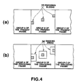
- Figure 4(a) shows a model of a part of codes in the present frame
- Figure 4(b) shows a model of a part of codes in the preceding frame.
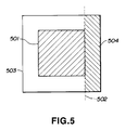
- Figure 5 shows a seeking area and a corresponding block positioned at the same position as the encoding block of the present frame.
- Figure 6 roughly shows an encoding device as a second embodiment of this invention.
- Figure 7 shows principal parts of the encoding device shown in Figure 6.
- Figure 8 roughly shows a decoding device corresponding to the encoding device shown in Figure 6.
- Figure 9 shows principal parts of the decoding device shown in Figure 8.
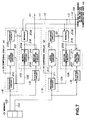
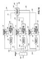
- Figure 10 roughly shows an encoding device as a third embodiment of the invention.
- Figure 11 shows principal parts of the encoding device shown in Figure 10.
- Figure 12 roughly shows a decoding device corresponding to the encoding device shown in Figure 10.
- Figure 13 shows principal parts of the decoding device shown in Figure 12.
- Figure 14 roughly shows an encoding device as a fourth embodiment of the invention.
- Figure 15 shows principal parts of the encoding device shown in Figure 14.
- Figure 16 shows principal parts of the decoding device corresponding to the encoding device shown in Figure 14.
- Figure 17 shows principal parts of the decoding device shown in Figure 16.
- Figure 2 shows a principal portion of an encoding device as a first embodiment of this invention.
- 1 shows an input terminal for inputting an analogue image signal
- 2 shows an A/D (analogue-to-digital) converting circuit for converting the input analogue signal to a digital image signal
- 3 shows a predictive error calculation circuit for calculating differences between an image signal of a present frame 30 and a predictive image signal 20 described afterward to provide a predictive error signal
- 6 shows an orthogonal transformation circuit for transforming the predictive error signal based on an orthogonal transformation
- 7 shows a quantizing circuit for quantizing orthogonal transformed coefficients 8 outputted from the orthogonal transformation.
- 9 shows an inverse quantizing circuit for inverse-quantizing quantized orthogonal-transformed coefficients (predictive error signal) 10
- 11 shows an inverse orthogonal transformation circuit for inverse orthogonal-transforming the inverse-quantized orthogonal-transformed coefficients
- 12 shows a reproduction image calculating circuit for calculating a reproduced image signal 15 of the present frame by adding a predictive error signal 13 inverse-orthogonal transformed and the predictive image signal
- 14 shows an image memory for storing the reproduced image signal of the present frame
- 16 shows a motion compensating circuit for compensating a reproduced image signal of the preceding frame 17 for a motion between present frame and preceding frame
- 18 shows a loop-filter circuit for filtering the motion-compensated image signal 19 to pass low frequency components in a two-dimensional frequency area for providing the predictive image signal 20.
- 21 shows a motion vector calculating circuit for calculating a motion vector 22 by comparing the image signal of the present frame 30 with the reproduced image signal of the preceding frame for every block to be recorded
- 23 shows a variable length encoding circuit for encoding the predictive error signal 10 to transform into codes having a variable-length
- 24 shows a code mixing circuit for mixing predictive error codes 25 and codes indicating motion vectors 22 to form transmissive-framed encoding codes
- 26 shows a buffer memory for temporarily storing the transmissive-framed encoded codes 27 to transmit them at a predetermined transmitting speed
- 28 shows an output terminal for outputting transmissive codes to a transmissive path.
- dividing and time-base expanding circuit which has a circuit for dividing the digital image signal codes provided by A/D converting circuit 2 into K (>2) of processing code groups, a circuit for further dividing each of the processing groups into a plurality of encoding code blocks, and a circuit for time-base expanding a signal composed of each of the processing code groups to lower the processing speed of each of the processing code groups.
- the dividing and time-base expanding circuit outputs the image signal of the present frame 30 in parallel.
- One of the image signals of the present frame 30 is supplied to the predictive error caclulation circuit 3.
- 31a,31b,31c and 31d show image encoding circuits which have the same structure composed of the circuits 3 ⁇ 26 as each other, and each of the circuits 31a,31b,31c and 31d handles one of K of the divided processing code groups. Further, in this embodiment, it is assumed that above-mentioned K is four and there are four image encoding circuits.
- 32 shows a composing circuit for composing one encoded code sequence from four channels of the encoded codes processed through the circuits 31a,31b,31c and 31d at every processing code group.
- the analogue image signal input from the input terminal1 is converted to the digital image signal by the A/D converting circuit 2.
- the analogue image signal is the HDTV signal
- a select sampling frequency for a luminance signal is 74.25 MHz and a select sampling frequency for a colour-difference signal is 37.125 MHz.
- Figure 3 shows a model of one frame of the digital image signal (codes) to explain a concrete example of dividing the digital image signal into four processing code groups.
- 33 shows one frame of digital codes arranged as actual pixels is arranged on an image.
- one frame of digital codes is divided into four processing code groups, namely, group A, group B, group C and group D.
- Each of the processing code groups is composed of codes corresponding to pixels which are in an unseparated area in a frame. In short, there are four divided areas in each frame.
- a writting operation for each frame of the digital image signal is carried out by respectively using four memory units.
- a reading operation is carried out such that four divided code groups, as shown in Figure 3, are read from the four memory units in parallel.
- each of processing code groups are read from one of the four memory units with a time-base expansion which is carried out so that a period of time for reading one processing code group does not exceed a period of time for one frame of the image signal. Owing to the time-base expansion, subsequent processing can be slow.
- each of the processing code groups are further divided into a plurality of encoding blocks 34, and divided encoding blocks are read out one after another from the each of the four memory units.
- Each of the encoding blocks are composed of (MxN) pixels having M continuous pixels in a horizontal direction of the frame and N continuous pixels in a vertical direction of the frame.
- Output codes from the dividing and time-base expanding circuit 29 are distributed among the four image encoding circuits 31a,31b,31c and 31d, and the four processing code groups are supplied to inputs (a) of four predictive error calculation circuits 3 and four motion vector calculating circuits 21 respectively.
- the four image encoding circuits 31a,31b,31c and 31d have the quite same circuits, therefore only the image encoding circuits 31a is described as follows.
- An input (b) of the predictive error calculation circuit 3 receives the predictive image signal (codes) 20.
- the circuit 3 calculates differences between the image signal (codes) of the present frame 30 and the predictive image signal (codes) 20, and output results of the calculation as the predictive error signal 6.
- the orthogonal transformation circuit 5 orthogonal transforms the predictive error signal (codes) 6 and outputs predictive-erred orthogonal transformed coefficients 8.
- DCT is used because as is well known it is easily realized.
- the quantizing circuit 7 quantized the orthogonal transformed coefficients 8, calculates predictive-erred, orthogonal transformed and quantized coefficients, and outputs them as the predictive error signal 10.
- the inverse-quantizing circuit 9 inverse-quantizes the predictive error signal (codes) 10, and the inverse-orthogonal transforming circuit 11 inverse-orthogonal transforms inverse-quantized coefficients and calculates the predictive error signal 13 including some inverse-quantized errors.
- the reproduction image calculating circuit 12 adds the predictive error signal 13 including some inverse-quantizing errors and the predictive signal 20 outputted from the loop-filter circuit 18, and calculates the reproduced image signal (codes) 15 of the present frame which is encoding for each of the encoding blocks.
- the image memory 14 stores the reproduced image codes 15 of the present frame and outputs the reproduced image codes (signal) of the preceding frame 17 stored therein.
- the motion vector calculating circuit 21 compares the image codes of the present frame 30 and the reproduced image codes of the preceding frame 17 stored in the image memory 14, and outputs motion vectors for each of the encoding blocks. Further, a process concerning with encoding blocks near boundaries among the four divided areas shown in Figure 3, is described afterward.
- the motion compensating circuit 16 compensates the reproduced image signal of the preceding frame 17 for the motion according to the motion vectors, and outputs the motion-compensated image signal.
- the motion compensating circuit 16 outputs codes of similar (MxN) pixels to (MxN) pixels of the encoding block to be encoded, at timings when the (MxN) pixels to be encoded input to the predictive-error calculation circuit. It is for that object that the motion compensating circuit 16 delays each pixels for various times and changes the order of the pixels.
- the loop-filter circuit 18 filters the motion-compensated image code of each of the encoding blocks to pass only low frequency components in the two-dimensional frequency area, and outputs filtered codes as the predictive signal (codes) 20.
- the predictive codes 20 are supplied to the predictive-error calculation circuit 3 and the reproduction image calculating circuit 12.
- the loop-filter circuit 18 executes above-mentioned filtering process by only using codes included in the same processing group as codes to be filtered.
- variable length encoding circuit 23 changes the order of the orthogonal transformed coefficients (the predictive error signal) 10 quantized by the quantizing circuits 7, and variable length encodes the quantized, re-ordered coefficients to output the predictive error codes (encoded codes) 25.
- the code mixing circuit 24 encodes the motion vectors, mixes the encoded motion vectors with the predictive error codes 25, and outputs the transmissive formed encoded codes 27 which is formed according to a predetermined data arrangement.
- the buffer memory 26 temporary stores the transmissive formed encoded codes 27, and supplies them to the composing circuit 32.
- the composing circuit 32 forms one encoded code sequence having the original high data rate. And the encoded code sequence is outputted from the output terminal 28 to the transmission path.
- Figure 4(a) shows a model of a part of codes in the present frame, especially codes in the processing code group B
- Figure 4(b) shows a model of a part of codes in the preceding frame, especially codes in the processing code group B.
- hatched portions 35 shows the encoding blocks, one of which positions near a boundary between the processing code groups A and B, other of which positions in a middle of the area corresponding to the processing code group B, and remaining one of which positions near a boundary between the processing code groups B and C.
- portions 36 shows seeking areas which are prepared corresponding to the blocks to be encoded respectively. In short, a block of (MxN) pixels having a highest correlation with the block 35 to be encoded is seeked in a respective seeking area 36.
- the four processing code groups are individually processed in the four image encoding circuits 31a ⁇ 31d. Therefore, each of the image encoding circuits is not able to use codes in other processing code groups. Accordingly, as shown in Figure 4(b), seeking areas corresponding to encoding blocks positioned near the boundaries are limited in smaller areas than other seeking areas. These limiting processes are executed by software processes carried out by the motion vector calculating circuit 21.
- the motion vector is not decided according to them.
- the motion vector cannot be decided according to (MxN) pixels including codes in the processing code group A, even if the (MxN) pixels are most similar to pixels of the encoding block. Accordingly, in that case, a motion vector indicating a motion from a left side to a right side cannot be selected. Then, that is to say, the motion vector is also limited.
- seeking areas for encoding blocks positioned near to edges of a frame are limited, and motion vectors for them are also limited.
- an encoding device as a first embodiment of this invention can slow a speed of processing for the motion compensation. In other words it can handle a higher speed signal than the prior device. It also can be easily controlled, can reduce the amount of the hardware, and can reduce the price thereof, because it divides the image signal into K number of processing groups and individually processes these groups.
- the above-mentioned first embodiment divides the image signal into a plurality of processing code groups by dividing an area of each frame in a horizontal direction. Further an encoding device, which divides the image signal by dividing an area of each frame in a vertical direction, can bring good results just like the above-mentioned first embodiment.
- the first embodiment divides the image signal into four processing groups, and an encoding device dividing the image signal two or more processing groups can bring good results like the first embodiment.
- the first embodiment detects a motion between adjacent frames
- a device detecting a motion between adjacent field or a device detecting a motion between an adaptable field or frame can bring good results as the first embodiments.
- one field or one frame is called one picture.
- a decoding device corresponding to above-mentioned encoding device can process the image signal passed through the transmission path by dividing the image signal into a plurality of processing code groups, as mentioned in following embodiments.
- the first embodiment of this invention greatly improves the slowing the processing speed, on the other hand motion vectors corresponding to the encoding blocks positioned near boundaries between areas corresponding to processing code groups are limited. These limitation may cause to come out inferior images around the boundaries.
- Figure 5 shows the seeking area 503 and a corresponding block positioned at the same position as the encoding block of the present frame.
- 502 shows a boundary between the processing code groups.
- the seeking area 503 is limited.
- 504 shows an invalid area for using the seeking area, and this invalid area is hatched in the Figure 5. In other words, this invalid area 504 sometimes causes to come out inferior images in the encoding block being close to the boundary 502.
- third and fourth embodiments can also solve such a problem to come out inferior images being close to the boundaries.
- FIG. 6 roughly shows an encoding device as a second embodiment of this invention.
- This device divides the image codes into three processing code groups.
- Each of the processing code groups corresponds a continuous divided area in a frame, as same as the first embodiment.
- Image data inputted from an input terminal 100 are supplied to a memory 101.
- the memory divides the image data into three processing code groups, and codes of each code processing groups are time-base expanded.
- the codes of the three code processing groups are supplied to dividing circuits 115,116 and 117 by passing lines 102,103 and 104 respectively.
- the dividing circuits 115,116 and 117 divide the codes into a plurality of code blocks respectively.
- Each of the code blocks is composed of codes corresponding to (AxB) pixels, A and B being 2 or more.
- each groups of image codes which is not divided into the code blocks is supplied to encoding process parts 118,119 and 120. Therefore, these encoding process parts 118,119 and 120 do not have to execute encodings by the code blocks as a unit.
- Each of the code blocks divided by the dividing circuits 115,116,117 is supplied to motion detecting and compensating parts 105,106,107.
- These parts 105,106,107 detect motion vectors and outputs vector codes according to the motion vectors to lines 151,152,153. They compensate image codes from the encoding process parts 118,119,102 via lines 121,122,123 for the motion in accordance with the motion vectors detected therein. The compensated image codes are returned to the encoding process parts 118,119,120 via lines 108,109,110.
- Encoded image codes and the vector codes are supplied to the composing circuit 127 via lines 124,125,126 for forming one encoded code sequence having a high data rate. Then, the encoded code sequence is outputted from an output terminal 129 via a line 128.
- Lines 111,112,113,114 are provided for handing or transferring some codes from one of the motion detecting and compensating parts 105,106,107 to another one. Accordingly, each of the parts 105,106,107 can refer a part of the image codes of other processing code groups. In other words, each of the parts 105,106,107 can refer some image codes in other continuous divided area.
- Figure 7 shows principal parts of the encoding device shown in Figure 6.
- the same numbers are used for the same elements in Figure 6.
- Image codes of the first image processing group are supplied to an encoding circuit 210 in the encoding process part 118 via the line 102.
- the encoding circuit 210 encodes them for compressing an amount of their data by using the image codes of the preceding frame, for instance, the encoding circuit 210 executes a well known predictive differential coding which calculates a predictive value by using the image codes of the preceding frame on the line 108 provided by the motion detecting and compensating part 105.
- the encoded codes outputted from the encoding circuit 210 are supplied to the composing circuit 127 as above described, and are also supplied to a local decoding circuit 212.
- the local decoding circuit 212 decodes the encoded codes by processing them in opposite processes which uses the image codes of the preceding frame on the line 108. Then decoded image codes from the local decoding circuit are supplied to a dividing circuit 228 which makes the same processing to divide them into the code blocks as the dividing circuit 115.
- a memory 208 is arranged to be able to store the decoded image codes an amount of which is more than one third of an amount of codes of one frame.
- the motion detecting circuit 206 receives the image codes of the present frame from the dividing circuit 115 and the image codes of the preceding frame from the memory 208 via a line 218. And the motion detecting circuit 206 detects the motion vectors for each code blocks by the same process as the motion vector calculating circuit 21 shown in Figure 2 and outputs the motion vector formed thereby to the line 151. The detected motion vectors are subsequently supplied to a motion compensating circuit 204 via a line 216 for compensating the decoded image codes of the preceding frame for the motion.
- the motion compensating circuit 204 works as same as the motion compensating circuit 16 also shown in Figure 2.
- circuits 205,207 and 209 in the motion detecting and compensating part 106 work as same as the circuits 204,206 and 208 in the motion detecting and compensating circuit 105 for another processing code group.
- circuits 211,213 and 229 in the encoding process part 119 works as same as the circuit 210,212 and 228 in the encoding process part 118.
- the lines 111 and 112 are provided for handing the image codes between memories 208 and 209, and lines 113 and 114 are provided for handing the image codes between the memory 209 and a memory being in the motion detecting and compensating part 107.
- the motion detecting circuit 206 and the motion compensating circuit 204 can refer above-mentioned area 504 shown in Figure 5.
- Image codes in the area 504 are handed from the memory 209 to the memory 208 through the line 111, and the memory 208 becomes to able to supply the image codes corresponding to the area 504 to the motion detecting circuit 206 and the motion compensating circuit 204.
- the motion detecting circuit 207 and the motion compensating circuit 205 can refer the image codes of the part of the first processing code group which are near to the boundary.
- the motion detecting and compensating part 106 can use a part of the codes in the third processing code group handed through the line 113 and the motion detecting and compensating part 107 can use a part of the codes in the second processing code group handed through the line 114.
- the encoding device described by using Figure 6 and Figure 7 solves the problem of limiting motion vectors, and prevents the generation of inferior images around the boundaries among the processing code groups.
- This device, as the second embodiment, also improves the slowing the speed of processing for encoding as same as the device described by using the Figure 2.
- Figure 8 roughly shows a decoding device corresponding to the encoding device shown in Figure 6.
- the encoded code sequence transmitted through the transmission path is input from an input terminal 330 and is supplied to a separating circuit 331.
- the separating circuit 331 distributes codes included in the encoded code sequence among three lines which is connected to decoding process parts 335,336,337 and picking out circuits 332,333,334 respectively.
- the decoding process parts 335,336,337 decode the encoded image codes respectively.
- the picking out circuits 332,333,334 pick up the vector codes.
- Motion detecting and compensating parts 304,305,306 receive the vector codes and restore the motion vectors.
- the parts 304,305,306 compensate decoded image codes from the decoding process parts 335,336,337 for the motion in accordance with the restored motion vectors. Compensated image codes are returned to the decoding process parts 335,336,337.
- Decoded image codes obtained by the decoding process parts 335,336,337 are supplied to a memory 338. Then the memory 338 outputs the decoded image codes in the order according to that of original image data.
- Lines 371,372,373,374 are provided for handing some codes from one of the motion detecting and compensating parts 304,305,306 to another one. Therefore, each of the parts 304,305,306 can refer a part of the image codes of other processing code groups as same as the parts 105,106,107 shown in Figure 6.
- Figure 9 shows principal parts of the decoding device shown in Figure 8.
- the same numbers are used for the same elements in Figure 8.
- the encoded image codes corresponding to the first image processing group are supplied to a decoding circuit 351 in the decoding process part 335.
- the decoding circuit 351 decodes the encoded image codes to restore original image codes by using the restored image codes of the preceding frame provided by the motion detecting and compensating part 304.
- the restored image codes outputted from the decoding circuit 351 are supplied to the memory 338 and a dividing circuit 357.
- the dividing circuit 357 divides the restored image codes into the code blocks by the same processing as the circuits 115,228.
- a memory 359 is arranged to be able to store the restored image codes (decoded image codes) an amount of which is more than one third of the amount of original image codes of one frame.
- a motion detecting circuit 355 receives the vector codes from the picking out circuit 332, and restores the motion vectors for each code blocks.
- the restored motion vectors are supplied to a motion compensating circuit 353 which compensates the restored image codes of the preceding frame for the motion.
- a concrete operation of the motion compensating circuit 353 is also same as the motion compensating circuit 16 shown in Figure 2.
- circuits 352,354,356,358,360 work as same as the circuits 351,353,355,357,359 for another processing code group.
- Lines 371,372 are provided for handing the image codes between the memories 359 and 360, and lines 373,374 are provided for handing the image codes between the memory 360 and a memory arranged in the part 306.
- each motion compensating circuits can refer the image codes included in other processing code group than the group which corresponds to the image codes mainly handled in the motion compensating circuit.
- the decoding device described by using Figure 8 and Figure 9 can compensate the restored image codes for the motion in accordance with motion vectors which is not limited. That is to say that inferior images around the boundaries are hardly occurred. Of course, the decoding device can slow the speed of processing relative to the prior decoding device.
- Figure 10 roughly shows an encoding device as a third embodiment of this invention.
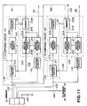
- Figure 11 shows principal parts of the encoding device shown in Figure 10.
- the same numbers are used for the similar elements in Figures 6 and 7.
- the encoding device has lines 141,142,143,144 for connecting the memory 101 to the memories provided in the motion detecting and compensating parts 105,106,107.
- the memory 101 is arranged to be able to supply a part of the image codes corresponding to the other processing code groups than the group which corresponds to the image codes mainly handled in the memories thereto, via the lines 141,142,143,144.
- each of the parts 105,106,107 can refer a part of the image codes of the other processing code groups.
- the encoding device shown in Figures 10 and 11 also solves the problem to limit motion vectors, and prevents to come out inferior images around the boundaries as same as the encoding device shown in Figures 6 and 7.
- the encoding device shown in Figures 10 and 11 can process the image signal more slowly than the device shown in Figures 6 and 7. In short, the device shown in Figures 10 and 11 can process a higher speed signal than the device shown in Figures 6 and 7. Because, each memories in the part 105,106,107 needs only a period for writing a part of the image codes included in other processing code group, but it does not need a period for reading the image codes to hand the other memories. However, the device shown in Figures 10 and 11 has to prepare more output terminals in the memory 101.
- Figure 12 roughly shows a decoding device corresponding to the encoding device shown in Figure 10.
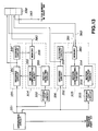
- Figure 13 shows principal parts of the decoding device shown in Figure 12.
- the same numbers are used for the similar elements in Figures 8 and 9.
- the decoding device shown in Figures 12 and 13 differs only in a structure for handing codes between the processing code groups from the decoding device shown in Figures 8 and 9.
- the decoding device has lines 380,381,382,383 for connecting the memory 338 to the memories provided in the motion detecting and compensating parts 304,305,306.
- the memory 338 is arranged to be able to supply a part of the decoded image codes included in the other processing code groups of the preceding frame via the lines 380,381,382,383.
- each of the parts 304,305,306 can refer a part of the decoded image codes of the other processing code groups.
- the decoding device shown in Figures 12 and 13 also can compensate the restored image codes for the motion, and can prevent to occur the inferior images as same as the decoding device shown in Figures 8 and 9.
- the decoding device shown in Figures 12 and 13 can process a higher speed signal than the decoding device shown in Figures 8 and 9.
- Figure 14 roughly shows an encoding device as a fourth embodiment of this invention.
- Figure 15 shows principal parts of the encoding device shown in Figure 14.
- the same numbers are also used for the similar elements in Figures 6,7,10,11.
- the encoding device shown in Figures 14 and 15 has lines 161,162,163,164 which are prepared for handing the codes to be written in the memories in the parts 105,106,107 to the memories in the other memories. A part of the image codes in the other processing code groups are also written in the memories via the lines 161,162,163,164.
- each of the parts 105,106,107 can refer a part of the image codes of the other processing code groups.
- the encoding device shown in Figures 14 and 15 also solves the same problem as the device shown in Figures 6 and 7 and the device shown in Figures 10 and 11.
- Figure 16 roughly shows a decoding device corresponding to the encoding device shown in Figure 14.
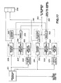
- Figure 17 shows principal parts of the decoding device shown in Figure 16.
- the same numbers are also used for the similar elements in Figures 8,9,12 and 13.
- the decoding device shown in Figure 16 and 17 has lines 390,391,392,393 which are prepared for handing the codes to be written in the memories in the parts 304,305,306 to the memories in the other memories. A part of the restored image codes in the other processing code groups are also written in the memories via the lines 390,391,392,393.
- each of the parts 304,305,306 can refer a part of the image signal of the other processing code groups.
- the decoding device shown in Figures 16 and 17 also has the same effects as the device shown in Figure 8 and 9 and the device shown in Figures 12 and 13.
- each of the embodiments of this invention improves the slowing the processing speed for processing the image signal to be compensated for the motion. In short, each of them can handle a higher speed signal than the prior device.
Landscapes
- Engineering & Computer Science (AREA)
- Multimedia (AREA)
- Signal Processing (AREA)
- Computing Systems (AREA)
- Theoretical Computer Science (AREA)
- Compression Or Coding Systems Of Tv Signals (AREA)
Applications Claiming Priority (6)
| Application Number | Priority Date | Filing Date | Title |
|---|---|---|---|
| JP19496492 | 1992-06-29 | ||
| JP4194964A JPH0622297A (ja) | 1992-06-29 | 1992-06-29 | 動き補償符号化装置 |
| JP194964/92 | 1992-06-29 | ||
| JP36013292A JPH06205398A (ja) | 1992-12-28 | 1992-12-28 | 動き補償予測符号化装置 |
| JP36013292 | 1992-12-28 | ||
| JP360132/92 | 1992-12-28 |
Publications (3)
| Publication Number | Publication Date |
|---|---|
| EP0577310A2 true EP0577310A2 (fr) | 1994-01-05 |
| EP0577310A3 EP0577310A3 (fr) | 1995-02-15 |
| EP0577310B1 EP0577310B1 (fr) | 2001-11-21 |
Family
ID=26508836
Family Applications (1)
| Application Number | Title | Priority Date | Filing Date |
|---|---|---|---|
| EP93304848A Expired - Lifetime EP0577310B1 (fr) | 1992-06-29 | 1993-06-22 | Dispositif de traitement d'image |
Country Status (3)
| Country | Link |
|---|---|
| US (1) | US5774592A (fr) |
| EP (1) | EP0577310B1 (fr) |
| DE (1) | DE69331174T2 (fr) |
Cited By (9)
| Publication number | Priority date | Publication date | Assignee | Title |
|---|---|---|---|---|
| EP0651579A1 (fr) * | 1993-10-29 | 1995-05-03 | STMicroelectronics S.A. | Système de traitement d'images haute définition |
| EP0650298A4 (fr) * | 1993-03-25 | 1995-05-17 | ||
| EP0720374A1 (fr) * | 1994-12-30 | 1996-07-03 | Daewoo Electronics Co., Ltd | Appareil pour le décodage en parallele de signaux vidéo numériques |
| EP0688134A3 (fr) * | 1994-06-14 | 1996-08-14 | Matsushita Electric Industrial Co Ltd | Appareil d'enregistrement de signal vidéo, appareil d'enregistrement et de reproduction de signal vidéo, dispositif de codage de signal vidéo, et appareil de transmission de signal vidéo |
| EP0710026A3 (fr) * | 1994-10-28 | 1998-01-21 | Matsushita Electric Industrial Co., Ltd. | Architecture parallèle pour un décodeur vidéo de télévision à haute définition avec un multiplicité de mémoires d'image indépendentes |
| WO1999038316A3 (fr) * | 1998-01-26 | 2000-01-20 | Tiernan Communications Inc | Procede et appareil de codage et decodage de signaux de television evolues |
| CN1051193C (zh) * | 1997-01-30 | 2000-04-05 | 广播电影电视部广播科学研究院电视研究所 | 利用现有数字广播设备传输高清晰度电视的系统 |
| WO2014166964A1 (fr) * | 2013-04-08 | 2014-10-16 | Fraunhofer-Gesellschaft zur Förderung der angewandten Forschung e.V. | Concept de codage permettant un codage multi-vues/de couche efficace |
| US10104386B2 (en) | 2013-01-04 | 2018-10-16 | Ge Video Compression, Llc | Efficient scalable coding concept |
Families Citing this family (8)
| Publication number | Priority date | Publication date | Assignee | Title |
|---|---|---|---|---|
| KR100292138B1 (ko) * | 1993-07-12 | 2002-06-20 | 이데이 노부유끼 | 디지탈비디오신호용송신기및수신기 |
| US6141447A (en) * | 1996-11-21 | 2000-10-31 | C-Cube Microsystems, Inc. | Compressed video transcoder |
| JP3950506B2 (ja) * | 1996-12-27 | 2007-08-01 | キヤノン株式会社 | 画像処理装置及び制御方法 |
| JP3408094B2 (ja) * | 1997-02-05 | 2003-05-19 | キヤノン株式会社 | 画像処理装置及びその方法 |
| JP2000184351A (ja) * | 1998-12-11 | 2000-06-30 | Office Noa:Kk | 動画像配信方法およびそのシステム |
| US7006665B2 (en) * | 2002-01-18 | 2006-02-28 | Lockheed Martin Corporation | Adaptive, product control and stabilization sub-system for camera-based optical character recognition, and a method of operating the same |
| JP5340172B2 (ja) * | 2008-05-20 | 2013-11-13 | パナソニック株式会社 | 画像符号化装置及び画像符号化方法 |
| KR101698797B1 (ko) * | 2010-07-27 | 2017-01-23 | 삼성전자주식회사 | 영상 데이터를 분할하여 부호화 및 복호화를 병렬 처리하는 장치 및 상기 장치의 동작 방법 |
Family Cites Families (10)
| Publication number | Priority date | Publication date | Assignee | Title |
|---|---|---|---|---|
| FR2617361A1 (fr) * | 1987-06-26 | 1988-12-30 | Eduvision Sa | Procede de stockage d'images de haute definition sur video-disque, codeur et decodeur pour la mise en oeuvre dudit procede |
| US5028995A (en) * | 1987-10-28 | 1991-07-02 | Hitachi, Ltd. | Picture signal processor, picture signal coder and picture signal interpolator |
| AU612543B2 (en) * | 1989-05-11 | 1991-07-11 | Panasonic Corporation | Moving image signal encoding apparatus and decoding apparatus |
| US5144426A (en) * | 1989-10-13 | 1992-09-01 | Matsushita Electric Industrial Co., Ltd. | Motion compensated prediction interframe coding system |
| GB2240231B (en) * | 1990-01-19 | 1994-03-30 | British Broadcasting Corp | High definition television coder/decoder |
| JPH0467259A (ja) * | 1990-07-09 | 1992-03-03 | Hitachi Ltd | 情報処理装置 |
| DE69029999T2 (de) * | 1990-07-20 | 1997-08-14 | Philips Electronics Nv | Vorrichtung zur Verarbeitung von Bewegungsvektoren |
| JPH04139986A (ja) * | 1990-09-29 | 1992-05-13 | Victor Co Of Japan Ltd | 画像信号の動き補償予測符号化/復号化装置 |
| US5138447A (en) * | 1991-02-11 | 1992-08-11 | General Instrument Corporation | Method and apparatus for communicating compressed digital video signals using multiple processors |
| US5235419A (en) * | 1991-10-24 | 1993-08-10 | General Instrument Corporation | Adaptive motion compensation using a plurality of motion compensators |
-
1993
- 1993-06-22 EP EP93304848A patent/EP0577310B1/fr not_active Expired - Lifetime
- 1993-06-22 DE DE69331174T patent/DE69331174T2/de not_active Expired - Lifetime
-
1995
- 1995-07-24 US US08/506,258 patent/US5774592A/en not_active Expired - Lifetime
Cited By (23)
| Publication number | Priority date | Publication date | Assignee | Title |
|---|---|---|---|---|
| EP0650298A4 (fr) * | 1993-03-25 | 1995-05-17 | ||
| EP0888012A1 (fr) * | 1993-03-25 | 1998-12-30 | Sony Corporation | Codage et décodage d'images en mouvement |
| US5946040A (en) * | 1993-03-25 | 1999-08-31 | Sony Corporation | Moving picture coding/decoding method and apparatus for decoders of various processing capability |
| EP0651579A1 (fr) * | 1993-10-29 | 1995-05-03 | STMicroelectronics S.A. | Système de traitement d'images haute définition |
| EP1006735A3 (fr) * | 1994-06-14 | 2000-10-25 | Matsushita Electric Industrial Co., Ltd. | Appareil d'enregistrement de signal vidéo, appareil d'enregistrement et de reproduction de signal vidéo, dispositif de codage de signal vidéo, et appareil de transmission de signal vidéo |
| US6526098B1 (en) | 1994-06-14 | 2003-02-25 | Matsushita Electric Industrial Co., Ltd. | High efficiency coding device and high efficiency coding method for image data |
| EP0688134A3 (fr) * | 1994-06-14 | 1996-08-14 | Matsushita Electric Industrial Co Ltd | Appareil d'enregistrement de signal vidéo, appareil d'enregistrement et de reproduction de signal vidéo, dispositif de codage de signal vidéo, et appareil de transmission de signal vidéo |
| US5677981A (en) * | 1994-06-14 | 1997-10-14 | Matsushita Electric Industrial Co., Ltd. | Video signal recording apparatus which receives a digital progressive scan TV signal and switches the progressive signal frame by frame alternately |
| US5978545A (en) * | 1994-06-14 | 1999-11-02 | Matsushita Electric Industrial Co., Ltd. | Video recording apparatus which accepts four different HDTV formatted signals |
| US5987215A (en) * | 1994-06-14 | 1999-11-16 | Matsushita Electric Industrial Co., Ltd. | Video signal recording apparatus, video signal recording and reproduction apparatus, video signal coding device, and video signal transmission apparatus |
| US6011900A (en) * | 1994-06-14 | 2000-01-04 | Matsushita Electric Industrial Co., Ltd. | Video signal recording apparatus, video signal recording and reproduction apparatus, video signal coding device, and video signal transmission apparatus |
| EP0710026A3 (fr) * | 1994-10-28 | 1998-01-21 | Matsushita Electric Industrial Co., Ltd. | Architecture parallèle pour un décodeur vidéo de télévision à haute définition avec un multiplicité de mémoires d'image indépendentes |
| EP0720374A1 (fr) * | 1994-12-30 | 1996-07-03 | Daewoo Electronics Co., Ltd | Appareil pour le décodage en parallele de signaux vidéo numériques |
| CN1051193C (zh) * | 1997-01-30 | 2000-04-05 | 广播电影电视部广播科学研究院电视研究所 | 利用现有数字广播设备传输高清晰度电视的系统 |
| WO1999038316A3 (fr) * | 1998-01-26 | 2000-01-20 | Tiernan Communications Inc | Procede et appareil de codage et decodage de signaux de television evolues |
| US10104386B2 (en) | 2013-01-04 | 2018-10-16 | Ge Video Compression, Llc | Efficient scalable coding concept |
| US10609396B2 (en) | 2013-01-04 | 2020-03-31 | Ge Video Compression, Llc | Efficient scalable coding concept |
| US11025928B2 (en) | 2013-01-04 | 2021-06-01 | Ge Video Compression, Llc | Efficient scalable coding concept |
| US11677966B2 (en) | 2013-01-04 | 2023-06-13 | Ge Video Compression, Llc | Efficient scalable coding concept |
| US12262031B2 (en) | 2013-01-04 | 2025-03-25 | Dolby Video Compression, Llc | Efficient scalable coding concept |
| WO2014166964A1 (fr) * | 2013-04-08 | 2014-10-16 | Fraunhofer-Gesellschaft zur Förderung der angewandten Forschung e.V. | Concept de codage permettant un codage multi-vues/de couche efficace |
| EP3758379A3 (fr) * | 2013-04-08 | 2021-02-24 | GE Video Compression, LLC | Concept de codage permettant un codage multi-vues/de couche efficace |
| US11582473B2 (en) | 2013-04-08 | 2023-02-14 | Ge Video Compression, Llc | Coding concept allowing efficient multi-view/layer coding |
Also Published As
| Publication number | Publication date |
|---|---|
| EP0577310A3 (fr) | 1995-02-15 |
| DE69331174T2 (de) | 2002-06-06 |
| US5774592A (en) | 1998-06-30 |
| DE69331174D1 (de) | 2002-01-03 |
| EP0577310B1 (fr) | 2001-11-21 |
Similar Documents
| Publication | Publication Date | Title |
|---|---|---|
| EP0577310B1 (fr) | Dispositif de traitement d'image | |
| US5251028A (en) | Apparatus for reducing quantization artifacts in an interframe hybrid coding system with motion compensation | |
| US5604539A (en) | Image processing method and apparatus | |
| EP1261208B1 (fr) | Codage de données continues d'image | |
| EP0388889B1 (fr) | Système de transformation d'un code bloc | |
| DE69027710T2 (de) | Bewegtbildsignalkodier- und -dekodiervorrichtung | |
| US6418168B1 (en) | Motion vector detection apparatus, method of the same, and image processing apparatus | |
| EP0732849A2 (fr) | Système de décodage d'images animées | |
| US6061397A (en) | Motion vector detecting device | |
| US4281344A (en) | Video interframe transform coding technique | |
| EP0710028A2 (fr) | Appareil pour le décodage d'image | |
| US5357282A (en) | Video decoder with parallel implementation | |
| US6223193B1 (en) | Macroblock variance estimator for MPEG-2 video encoder | |
| JPS60186179A (ja) | 画像信号の予測符号化方式とその装置 | |
| US5424777A (en) | Time-varying image signal coding/decoding system | |
| US4656511A (en) | Video signal compressing and coding apparatus | |
| US5748248A (en) | Real time motion vector processing of image data | |
| US5394190A (en) | Video signal encoding apparatus | |
| US5825928A (en) | Decoding apparatus for error concealment considering motion directions of moving images | |
| US6020926A (en) | Motion estimation block matching speedup | |
| JP2776284B2 (ja) | 画像符号化装置 | |
| US5774590A (en) | Image data reproducing apparatus | |
| US20030210830A1 (en) | Image signal distortion removal apparatus, and image signal distortion removal method | |
| KR100295837B1 (ko) | 동영상 부호화를 위한 움직임 추정장치 | |
| KR100504416B1 (ko) | 화상부호화방법및장치 |
Legal Events
| Date | Code | Title | Description |
|---|---|---|---|
| PUAI | Public reference made under article 153(3) epc to a published international application that has entered the european phase |
Free format text: ORIGINAL CODE: 0009012 |
|
| AK | Designated contracting states |
Kind code of ref document: A2 Designated state(s): DE ES FR GB IT NL |
|
| PUAL | Search report despatched |
Free format text: ORIGINAL CODE: 0009013 |
|
| AK | Designated contracting states |
Kind code of ref document: A3 Designated state(s): DE ES FR GB IT NL |
|
| 17P | Request for examination filed |
Effective date: 19950629 |
|
| 17Q | First examination report despatched |
Effective date: 19970902 |
|
| GRAG | Despatch of communication of intention to grant |
Free format text: ORIGINAL CODE: EPIDOS AGRA |
|
| GRAG | Despatch of communication of intention to grant |
Free format text: ORIGINAL CODE: EPIDOS AGRA |
|
| GRAH | Despatch of communication of intention to grant a patent |
Free format text: ORIGINAL CODE: EPIDOS IGRA |
|
| GRAH | Despatch of communication of intention to grant a patent |
Free format text: ORIGINAL CODE: EPIDOS IGRA |
|
| GRAA | (expected) grant |
Free format text: ORIGINAL CODE: 0009210 |
|
| RIC1 | Information provided on ipc code assigned before grant |
Free format text: 7H 04N 7/50 A |
|
| AK | Designated contracting states |
Kind code of ref document: B1 Designated state(s): DE ES FR GB IT NL |
|
| PG25 | Lapsed in a contracting state [announced via postgrant information from national office to epo] |
Ref country code: NL Free format text: LAPSE BECAUSE OF FAILURE TO SUBMIT A TRANSLATION OF THE DESCRIPTION OR TO PAY THE FEE WITHIN THE PRESCRIBED TIME-LIMIT Effective date: 20011121 |
|
| REG | Reference to a national code |
Ref country code: GB Ref legal event code: IF02 |
|
| REF | Corresponds to: |
Ref document number: 69331174 Country of ref document: DE Date of ref document: 20020103 |
|
| ET | Fr: translation filed | ||
| NLV1 | Nl: lapsed or annulled due to failure to fulfill the requirements of art. 29p and 29m of the patents act | ||
| PG25 | Lapsed in a contracting state [announced via postgrant information from national office to epo] |
Ref country code: ES Free format text: LAPSE BECAUSE OF FAILURE TO SUBMIT A TRANSLATION OF THE DESCRIPTION OR TO PAY THE FEE WITHIN THE PRESCRIBED TIME-LIMIT Effective date: 20020530 |
|
| PLBE | No opposition filed within time limit |
Free format text: ORIGINAL CODE: 0009261 |
|
| STAA | Information on the status of an ep patent application or granted ep patent |
Free format text: STATUS: NO OPPOSITION FILED WITHIN TIME LIMIT |
|
| 26N | No opposition filed | ||
| PGFP | Annual fee paid to national office [announced via postgrant information from national office to epo] |
Ref country code: GB Payment date: 20110621 Year of fee payment: 19 |
|
| PGFP | Annual fee paid to national office [announced via postgrant information from national office to epo] |
Ref country code: IT Payment date: 20110608 Year of fee payment: 19 |
|
| PGFP | Annual fee paid to national office [announced via postgrant information from national office to epo] |
Ref country code: FR Payment date: 20110713 Year of fee payment: 19 |
|
| PGFP | Annual fee paid to national office [announced via postgrant information from national office to epo] |
Ref country code: DE Payment date: 20110630 Year of fee payment: 19 |
|
| GBPC | Gb: european patent ceased through non-payment of renewal fee |
Effective date: 20120622 |
|
| PG25 | Lapsed in a contracting state [announced via postgrant information from national office to epo] |
Ref country code: IT Free format text: LAPSE BECAUSE OF NON-PAYMENT OF DUE FEES Effective date: 20120622 |
|
| REG | Reference to a national code |
Ref country code: FR Ref legal event code: ST Effective date: 20130228 |
|
| REG | Reference to a national code |
Ref country code: DE Ref legal event code: R119 Ref document number: 69331174 Country of ref document: DE Effective date: 20130101 |
|
| PG25 | Lapsed in a contracting state [announced via postgrant information from national office to epo] |
Ref country code: FR Free format text: LAPSE BECAUSE OF NON-PAYMENT OF DUE FEES Effective date: 20120702 Ref country code: DE Free format text: LAPSE BECAUSE OF NON-PAYMENT OF DUE FEES Effective date: 20130101 Ref country code: GB Free format text: LAPSE BECAUSE OF NON-PAYMENT OF DUE FEES Effective date: 20120622 |