EP0577320A1 - Anordnung von Hornstrahlern mit stufenförmigem Septumpolarisator - Google Patents
Anordnung von Hornstrahlern mit stufenförmigem Septumpolarisator Download PDFInfo
- Publication number
- EP0577320A1 EP0577320A1 EP93304893A EP93304893A EP0577320A1 EP 0577320 A1 EP0577320 A1 EP 0577320A1 EP 93304893 A EP93304893 A EP 93304893A EP 93304893 A EP93304893 A EP 93304893A EP 0577320 A1 EP0577320 A1 EP 0577320A1
- Authority
- EP
- European Patent Office
- Prior art keywords
- waveguide section
- section
- horn
- waveguide
- septum
- Prior art date
- Legal status (The legal status is an assumption and is not a legal conclusion. Google has not performed a legal analysis and makes no representation as to the accuracy of the status listed.)
- Withdrawn
Links
- 230000000712 assembly Effects 0.000 claims abstract description 17
- 238000000429 assembly Methods 0.000 claims abstract description 17
- 230000008878 coupling Effects 0.000 claims abstract description 7
- 238000010168 coupling process Methods 0.000 claims abstract description 7
- 238000005859 coupling reaction Methods 0.000 claims abstract description 7
- 230000010287 polarization Effects 0.000 claims abstract description 6
- 230000005855 radiation Effects 0.000 claims description 21
- 230000001902 propagating effect Effects 0.000 claims description 4
- 230000005684 electric field Effects 0.000 description 31
- 230000010363 phase shift Effects 0.000 description 17
- 238000010276 construction Methods 0.000 description 12
- 230000005540 biological transmission Effects 0.000 description 6
- 238000006243 chemical reaction Methods 0.000 description 6
- 239000013598 vector Substances 0.000 description 5
- 230000004323 axial length Effects 0.000 description 3
- 238000004891 communication Methods 0.000 description 3
- 230000003247 decreasing effect Effects 0.000 description 3
- 238000010586 diagram Methods 0.000 description 3
- 238000004519 manufacturing process Methods 0.000 description 3
- 230000009467 reduction Effects 0.000 description 3
- 230000004044 response Effects 0.000 description 2
- 230000007423 decrease Effects 0.000 description 1
- 230000001934 delay Effects 0.000 description 1
- 230000005670 electromagnetic radiation Effects 0.000 description 1
- 230000013011 mating Effects 0.000 description 1
- 238000000034 method Methods 0.000 description 1
- 230000004048 modification Effects 0.000 description 1
- 238000012986 modification Methods 0.000 description 1
- 238000001228 spectrum Methods 0.000 description 1
- 230000009466 transformation Effects 0.000 description 1
Images
Classifications
-
- H—ELECTRICITY
- H01—ELECTRIC ELEMENTS
- H01Q—ANTENNAS, i.e. RADIO AERIALS
- H01Q13/00—Waveguide horns or mouths; Slot antennas; Leaky-waveguide antennas; Equivalent structures causing radiation along the transmission path of a guided wave
- H01Q13/02—Waveguide horns
- H01Q13/025—Multimode horn antennas; Horns using higher mode of propagation
- H01Q13/0258—Orthomode horns
-
- H—ELECTRICITY
- H01—ELECTRIC ELEMENTS
- H01P—WAVEGUIDES; RESONATORS, LINES, OR OTHER DEVICES OF THE WAVEGUIDE TYPE
- H01P1/00—Auxiliary devices
- H01P1/165—Auxiliary devices for rotating the plane of polarisation
- H01P1/17—Auxiliary devices for rotating the plane of polarisation for producing a continuously rotating polarisation, e.g. circular polarisation
- H01P1/173—Auxiliary devices for rotating the plane of polarisation for producing a continuously rotating polarisation, e.g. circular polarisation using a conductive element
Definitions
- This invention relates to a microwave horn radiator assembly for radiating circularly polarized electromagnetic waves from a radiator at a front portion of the assembly, the assembly including an orthomode transducer providing a conversion between linearly and circularly polarized radiation. More particularly, the invention employs a septum increasing stepwise monotonically in height from a bottom wall to a top wall of a square waveguide to provide two rectangular waveguide ports at a back end of the assembly, opposite the horn radiator, to provide the conversion between linearly and circularly polarized radiation.
- the assembly also includes plural stepped waveguide sections forming an impedance matching section behind the horn radiator, and a set of capacitive posts between the matching section and the septum.
- An antenna comprising an array of radiators providing circularly polarized radiation may be employed in numerous situations, including a mounting of the antenna on board a spacecraft to provide for communication between the spacecraft and a station on the earth.
- each of the radiators is formed as a part of a radiator assembly which includes microwave structures for converting a linearly polarized electromagnetic wave to a circularly polarized electromagnetic wave for transmission of a microwave signal, and for converting from circularly polarized radiation to linearly polarized radiation upon reception of a microwave signal.
- an orthomode transducer to provide for the conversion between the linearly and circularly polarized radiation.
- the microwave structure for polarization conversion is substantially larger than the radiator itself.
- perpendicularly oriented rectangular waveguides have been employed to provide for both right-hand and left-hand circularly polarized waves.
- a further disadvantage in the foregoing construction is excessive complexity in the manufacturing process required to produce the microwave structure.
- a large bandwidth is advantageous in the use of communication equipment, and the foregoing construction has been disadvantageous in respect to a limitation of the maximum bandwidth available for communication.
- the physical size has been enlarged also because of a need for numerous tuning screws, the need for such tuning also complicating the manufacture and set-up procedure.
- the radiator should be operated in such a fashion as to minimize mutual coupling between signals of the various radiators of the antenna array.
- a multiple-band horn radiator assembly and an antenna comprising an array of such horn radiator assemblies which incorporate the invention to provide sufficient bandwidth to combine functions of transmit, receive, and tracking frequencies in each horn radiator assembly.
- the construction of the invention minimizes hardware, reduces weight, and saves manufacturing time.
- Each horn radiator assembly comprises a waveguide section of square cross-section arranged coaxially with a circular cylindrical horn.
- the horn provides a radiating aperture for radiation of circularly polarized electromagnetic waves.
- the waveguide section is coupled via an impedance matching section to the horn radiator.
- the septum extends from the bottom wall to a top wall of the waveguide section and bisects a rear portion of the waveguide section into two rectangular waveguides which serve as input ports of an orthomode transducer for injecting linearly polarized radiation to be converted to either right or left-handed circularly polarized waves.
- the septum introduces a phase-shift characteristic of decreasing phase shift with increasing frequency. This phase-shift characteristic is counterbalanced by a line of capacitive teeth disposed on the bottom wall in front of the septum to provide a phase-shift characteristic wherein phase shift increases with increasing frequency.
- the diameter of the horn radiator is larger than the height of a sidewall of the waveguide section, and the impedance matching section comprises two waveguide sections of decreasing cross-sectional sides wherein a forward section connecting with the horn is circular and a back section connecting with the aforementioned waveguide section is square in cross section.
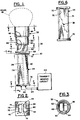
- Figs. 1 - 8 show a horn radiator assembly 30 which, in accordance with the invention, comprises a circular cylindrical horn 32, a waveguide section 34 of square cross-section, and an impedance matching section 36 which connects a front end of the waveguide section 34 with a back end of the horn 32.
- the waveguide section 34 includes a septum 38 which extends along a center line of the waveguide section 34, and bisects the back end of the waveguide section 34 to form two ports 40 and 42.
- a transmit/receive circuit 44 connects with the ports 40 and 42 for applying linearly polarized radiation to one or both of the ports 40-42 to be converted by the assembly 30 to circularly polarized radiation which radiates as a beam 46 from the horn 32.
- the assembly 30 operates also in reciprocal fashion such that a circularly polarized wave, incident upon the horn 32, is converted to a linearly polarized electromagnetic wave appearing in either the port 40 or 42, depending on the direction of circular polarization, to be received at the circuit 44.
- the impedance matching section 36 comprises a forward section of a waveguide 48 of circular cross-section which connects with a back end of the horn 32, and a rear section of waveguide 50 of square cross-section which interconnects the forward waveguide section 48 with a front end of the waveguide section 34.
- the diameter of the forward waveguide section 48 is smaller than the diameter of the horn 32.
- the height of a wall, such as a sidewall 52 of the rear waveguide section 50 is smaller than a diameter of the forward waveguide section 58.
- the decreasing magnitude of the dimensions of the waveguide sections 48 and 50 relative to the dimension of the horn 32 provides for a stepped configuration to the impedance matching section 36.
- the square waveguide section 50 includes the aforementioned sidewall 52, and a sidewall 54, and top and bottom walls 56 and 58 which are joined by the sidewalls 52 and 54.
- the forward waveguide section 48 comprises a cylindrical sidewall 60 and a back wall 62.
- the horn 32 comprises a cylindrical sidewall 64 and a shelf 66 at an interface between the horn 32 and the forward waveguide section 48.
- the horn 32 and the impedance matching section 36 are formed integrally as a unitary structure which is provided with a flange 68 at the back end of the impedance matching section 36 for mating with the waveguide section 34 via a flange 70 located at the front end of the waveguide section 34.
- a further flange 72 is provided at the back end of the waveguide section 34 for connection with other microwave components, such as components of the circuit 44.
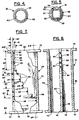
- the waveguide section 34 comprises a top wall 74 and a bottom wall 76 which are joined by sidewalls 78 and 80.
- the septum 38 stands on the bottom wall 76, and extends from a middle portion of the waveguide section 34 towards the back end at the flange 72.
- the septum 38 has a relatively short height, the height extending stepwise, via a succession of steps 84, to a back portion 86 of the septum wherein the septum 38 extends the full height of the waveguide section 34 from the bottom wall 76 to the top wall 74.
- the steps 84 are of differing heights and widths.
- the widths of the steps 84 vary from approximately 0.1 to 0.25 wavelength at a nominal frequency of the electromagnetic radiation propagating through the waveguide section 34.
- the radiator assembly 30 operates over a frequency range of 11.0 to 13.4 GHz (gigahertz) and over a range of 13.7 to 18.0 GHz.
- a frequency band of 11.7 to 12.2 GHz or a band of 12.2 to 12.7 GHz could be used for transmission; a band of 14.0 to 14.5 GHz or a band of 17.3 to 17.8 GHz could be used for reception, and a band of 15.5 to 16.5 GHz could be used for satellite tracking.
- a nominal value of frequency of 12.45 GHz is selected, this corresponding to a free-space wavelength of 0.948 inches.
- the largest dimensions of the steps are found in the middle of the series of steps 84. Smaller dimensions of the steps 84 are found near both ends of the series of the steps 84.
- Incremental heights of the steps 84 vary from approximately 0.035 to 0.200 wavelengths at the nominal value of the radiation frequency, and the incremental widths of the steps 84 vary from approximately 0.1 to 0.25 wavelengths.
- the actual heights of the steps 84 as represented by the legends A2 -A8 in Fig. 7, are provided relative to a reference plane at the outside edge of the bottom wall 76.
- the actual locations of the riser portions of each of the steps 84, as represented by the legends B1 - B8 in Fig. 7, are provided relative to a reference plane at the front surface of the front flange 70 of the waveguide section 34.
- the following dimensions are employed in the preferred embodiment of the invention.
- the dimensions A2, A3, and A4 measure, respectively, 0.080, 0.126, and 0.174 inches.
- the dimensions A5, A6, A7, and A8 measure, respectively, 0.254, 0.313, 0.572, and 0.613 inches.
- the dimensions B1, B2, B3, and B4 measure, respectively, 1.017, 1.100, 1.215, and 1.478 inches.
- the dimensions B5, B6, B7, and B8 measure, respectively, 1.713, 1.958, 2.055, and 2.423 inches.
- the smaller step widths are approximately one-tenth wavelength
- the larger step widths are approximately one-quarter wavelength.
- the septum 38 has a thickness of 0.030 inches.
- a characteristic of the septum 38 is that it introduces a phase shift versus frequency to radiation propagating past the septum 38 wherein the phase shift decreases with increasing frequency.
- Such a phase shift characteristic is similar to that disclosed for a capacitive ridge in U. S. patent 4,654,611 of Wong et al.
- a set of teeth 88 are provided upstanding from the bottom wall 76 and are arranged in a line colinear with the septum 38 to introduce capacitance to the waveguide section 34.
- the capacitance introduced by the teeth 88 has a phase-shift characteristic to radiation propagating in the waveguide section 34 wherein the amount of phase shift increases with increasing frequency of the radiation.
- Four of the teeth 88 are provided in the preferred embodiment of the invention, the teeth 88 being spaced apart from each other and from the front end 82 of the septum 38 by spaces 90. With increasing frequency of the radiation, the increment in phase shift introduced by the row of teeth 88 tends to cancel the decrement in phase shift introduced by the septum 38 so as to obtain the desired wide bandwidth characteristic of the radiator assembly.
- the teeth 88 have the same height and the same width, and the spaces 90 are all equal. The height of the teeth 88, relative to the reference plane, as designated by the legend A1 in Fig.
- the thickness of the bottom wall 76 is 0.040 inches.
- the teeth 88 are positioned periodically with a period of 0.242 inches as measured between centers of the teeth.
- the spacing between the teeth 88, as represented by the spaces 90, is 0.095 inches.
- the horn 32 has an axial length, as measured from the shelf 66 to the front of the horn 32, of 0.675 inches.
- the thickness of the sidewall 64 is 0.007 inches.
- the axial length, as measured from the back wall 62 to the shelf 66 is 0.310 inches.
- the axial length of the rear waveguide section 50 is 0.593 inches.
- the inside diameter of the horn 32 is 1.039 inches.
- the wall thickness of the forward waveguide section 48 is 0.018 inches.
- the inside diameter of the forward waveguide section 48 is 0.850 inches.
- the cross-sectional dimensions of the rear waveguide section 50 are the same as those of the waveguide section 34 wherein the interior wall heights are 0.583 inches.
- the stepwise construction of the impedance matching section 36 minimizes mutual coupling among horns 32 in an array of radiator assemblies 30 such as that to be described in Fig. 19.
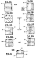
- a right-handed circularly polarized wave is presumed to be incident upon the horn 32, the wave having horizontally polarized components of electric field depicted as arrows in Fig. 9A, and vertically polarized components of electric field as depicted by arrows in Fig. 9B.
- the electric field components represented by Figs. 9A and 9B occur in the front portion of the waveguide section 34.
- changes occur in the electric field components as indicated by Figs. 10A-10B and Figs. 11A-11B.
- Figs 10A-10B represent a region of the septum 38 towards the front end of the septum, while Figs.
- FIG. 11A-11B represent a region of the septum 38 towards the back end of the septum.
- the horizontally polarized electric field components are reconfigured, the reconfiguration continuing into Fig. 11A wherein the energy of the electric field has now been converted into opposed electric field vectors located on opposite sides of the septum 38 and extending in opposite direction.
- Figs. 10B and 11B With respect to the vertically polarized electric field components, a part of the electric field appears on each side of the septum 38, as shown in Figs. 10B and 11B, however, the direction of the electric field vectors remains the same on both sides of the septum 38.
- OMT orthomode transducer
- Fig. 12A shows the opposed vertical fields on both sides of the septum 38 resulting from the horizontally polarized field of Fig. 9A, and Fig.
- FIG. 12B shows electric fields pointing in the same direction on opposite sides of the septum 38 resulting from the vertically polarized field of Fig. 9B.
- the amplitudes of the fields of Fig. 9B and Fig. 9A are in phase quadrature to produce the right-handed circular polarization.
- Figs. 10A, 11A, and 12A there has been a phase shift of 90 degrees which brings the amplitudes of the electric fields of Figs. 12A in phase with the amplitudes of the electric fields in Fig. 12B.
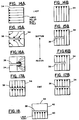
- the Figs. 14A-18 provide a description of the operation of the waveguide section 34 for the case of the left-handed circularly polarized (LHCP) electromagnetic wave.
- the vectorial representations of the electric fields of Figs. 14B, 15B, 16B, and 17B are the same as the electric fields portrayed in the Figs. 9B, 10B, 11B, and 12B, respectively.
- the electric field vectors are oriented in the opposite sense to the electric field vectors of Fig. 9A.
- the electric fields have the same patterns as do the fields of Figs. 10A, 11A, and 12A, respectively, but are oriented in the opposite sense.
- 1 can provide for either a right-handed or left-handed circularly polarized wave by applying the electric field respectively to either port 42 or Port 40.
- Coupling of the circuit 44 to the port 40 (Figs. 1-2) is provided via line 92, and the coupling of the circuit 44 to the port 42 is provided by line 94.
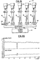
- Fig. 19 shows an antenna 96 comprising an array of radiator assemblies 30 with their horns 32 arranged side-by-side to produce a beam of radiation for transmission and reception of radiant signals.
- the transmit/receive circuit 44 is coupled via lines 98 and 100 to a beamformer 102.
- the beamformer 102 connects with the ports 40 and 42 of each of the radiator assemblies 30 via diplexers 104 and 106 to allow operation of transmit and receive functions in different portions of the frequency bands over which the radiator assemblies 30 are operative.
- the beamformer 102 is operative to provide phase shift and/or delays of signals applied to one of the radiator assemblies 30 relative to other ones of the radiator assemblies 30 so as to form and to direct a beam of radiation produced by the the horns 32.
- the beamformer 102 is operative to divide power equally among the radiator assemblies 30 for the transmission of radiation, and to combine the power of radiant signals received from the radiator assemblies 30 during reception of an incoming electromagnetic signal.
- a left-handed or right-handed circularly polarized wave can be transmitted or received.
- Fig. 20 shows a graph representing the frequency response of a horn radiator assembly 30.
- the graph includes two traces, the upper trace representing amplitude of a transmitted or received signal as a function of frequency, and the lower trace representing phase shift of the transmitted or received signal as a function of frequency.
- the amplitude variations are indicated in decibels, the phase shift is indicated in degrees, and the frequency is presented in units of gigahertz.
- a region of attenuation and rapid phase shift occurs in a relatively narrow frequency band centered at a frequency of approximately 13.5 GHz. This divides the useful spectrum of the radiator assembly 30 into a lower frequency band and a higher frequency band.
- the invention provides for a radiator assembly 30 having a smaller overall configuration than has been possible heretofore.
- a significant savings in space, over that of previous microwave structures, is afforded by the lack of tuning screws, by the parallel arrangement of the two waveguide ports 40 and 42, and by the reduction in overall length of the septum 38 through use of the numerous steps 84.
- the use of the numerous steps 84 also provides for a significant reduction in reflected waves, and the use of the capacitive teeth 88 serves to provide the desired broad bandwidth.
- the reduction in size facilitates construction of the array antenna 96, and the stepped configuration of the impedance matching structure 36 reduces mutual coupling between the radiating horns 32 of the antenna 96.
Landscapes
- Waveguide Aerials (AREA)
Applications Claiming Priority (2)
| Application Number | Priority Date | Filing Date | Title |
|---|---|---|---|
| US07/906,162 US5305001A (en) | 1992-06-29 | 1992-06-29 | Horn radiator assembly with stepped septum polarizer |
| US906162 | 1992-06-29 |
Publications (1)
| Publication Number | Publication Date |
|---|---|
| EP0577320A1 true EP0577320A1 (de) | 1994-01-05 |
Family
ID=25422021
Family Applications (1)
| Application Number | Title | Priority Date | Filing Date |
|---|---|---|---|
| EP93304893A Withdrawn EP0577320A1 (de) | 1992-06-29 | 1993-06-23 | Anordnung von Hornstrahlern mit stufenförmigem Septumpolarisator |
Country Status (2)
| Country | Link |
|---|---|
| US (1) | US5305001A (de) |
| EP (1) | EP0577320A1 (de) |
Cited By (5)
| Publication number | Priority date | Publication date | Assignee | Title |
|---|---|---|---|---|
| GB2301484A (en) * | 1995-05-29 | 1996-12-04 | Matsushita Electric Industrial Co Ltd | Feed-horn with helical antenna element |
| EP0751582A3 (de) * | 1995-06-27 | 1997-04-09 | Loral Space Systems Inc | Multifunktionelle Antennenanordnung mit Hornstrahler |
| FR2831997A1 (fr) * | 2001-11-07 | 2003-05-09 | Thomson Licensing Sa | Module guide d'ondes separateur en frequence a polarisation circulaire double et emetteur-recepteur le comportant |
| WO2003083995A1 (en) * | 2002-03-27 | 2003-10-09 | The Boeing Company | Dual reflector antenna with waveguide diplexer and omt mounted on back of main reflector |
| EP2869396A1 (de) * | 2013-11-04 | 2015-05-06 | Thales | Leistungsverteiler, der eine T-Kupplung auf der E-Ebene umfasst, Speisenetzwerk und Antenne, die ein solches Speisenetzwerk umfasst |
Families Citing this family (22)
| Publication number | Priority date | Publication date | Assignee | Title |
|---|---|---|---|---|
| FR2766625B1 (fr) * | 1997-07-28 | 1999-09-03 | Alsthom Cge Alcatel | Antenne a polarisation circulaire un sens |
| FR2777700B1 (fr) * | 1998-04-20 | 2000-07-07 | Org Europeenne Telecommunications Par Satellite Eutelsat | Agencement de convertisseur de frequences pour antennes parabolique |
| US6535174B2 (en) * | 1999-12-20 | 2003-03-18 | Hughes Electronics Corporation | Multi-mode square horn with cavity-suppressed higher-order modes |
| US6507323B1 (en) * | 2001-03-28 | 2003-01-14 | Rockwell Collins, Inc. | High-isolation polarization diverse circular waveguide orthomode feed |
| JP3879548B2 (ja) * | 2002-03-20 | 2007-02-14 | 三菱電機株式会社 | 導波管形偏分波器 |
| US6950073B2 (en) * | 2002-08-20 | 2005-09-27 | Aerosat Corporation | Communication system with broadband antenna |
| US7034774B2 (en) * | 2004-04-22 | 2006-04-25 | Northrop Grumman Corporation | Feed structure and antenna structures incorporating such feed structures |
| US7999560B2 (en) * | 2005-10-27 | 2011-08-16 | Masprodenkoh Kabushikikaisha | Interference exclusion capability testing apparatus |
| US7545323B2 (en) * | 2005-10-31 | 2009-06-09 | The Boeing Company | Phased array antenna systems and methods |
| US7551136B1 (en) * | 2006-07-24 | 2009-06-23 | The Boeing Company | Multi-beam phased array antenna for limited scan applications |
| US7852277B2 (en) * | 2007-08-03 | 2010-12-14 | Lockheed Martin Corporation | Circularly polarized horn antenna |
| FR2923657B1 (fr) * | 2007-11-09 | 2011-04-15 | Thales Sa | Procede de fabrication d'une source hyperfrequence monobloc electroformee a lame epaisse |
| US8525616B1 (en) * | 2009-04-14 | 2013-09-03 | Lockheed Martin Corporation | Antenna feed network to produce both linear and circular polarizations |
| TWM372539U (en) * | 2009-08-19 | 2010-01-11 | Microelectronics Tech Inc | Polarizer and waveguide antenna apparatus using the same |
| US9698492B2 (en) * | 2015-01-28 | 2017-07-04 | Northrop Grumman Systems Corporation | Low-cost diplexed multiple beam integrated antenna system for LEO satellite constellation |
| US9859597B2 (en) | 2015-05-27 | 2018-01-02 | Viasat, Inc. | Partial dielectric loaded septum polarizer |
| US9640847B2 (en) | 2015-05-27 | 2017-05-02 | Viasat, Inc. | Partial dielectric loaded septum polarizer |
| US10020554B2 (en) | 2015-08-14 | 2018-07-10 | Viasat, Inc. | Waveguide device with septum features |
| US10096876B2 (en) | 2015-11-13 | 2018-10-09 | Viasat, Inc. | Waveguide device with sidewall features |
| WO2018017518A2 (en) | 2016-07-21 | 2018-01-25 | Astronics Aerosat Corporation | Multi-channel communications antenna |
| US10992052B2 (en) | 2017-08-28 | 2021-04-27 | Astronics Aerosat Corporation | Dielectric lens for antenna system |
| EP3959773B1 (de) | 2019-06-19 | 2023-06-07 | Viasat, Inc. | Doppelband-septum-polarisator |
Citations (6)
| Publication number | Priority date | Publication date | Assignee | Title |
|---|---|---|---|---|
| US3955202A (en) * | 1975-04-15 | 1976-05-04 | Macrowave Development Laboratories, Inc. | Circularly polarized wave launcher |
| US4100514A (en) * | 1977-04-28 | 1978-07-11 | Gte Sylvania Incorporated | Broadband microwave polarizer device |
| US4122406A (en) * | 1977-05-12 | 1978-10-24 | Edward Salzberg | Microwave hybrid polarizer |
| US4654611A (en) | 1985-10-02 | 1987-03-31 | Hughes Aircraft Company | Broadband waveguide phase shifter |
| EP0218549A2 (de) * | 1985-10-11 | 1987-04-15 | HUBER & SUHNER AG KABEL-, KAUTSCHUK-, KUNSTSTOFF-WERKE | Hohlleiteranordnung |
| CH664848A5 (en) * | 1984-08-22 | 1988-03-31 | Huber+Suhner Ag | Circular polariser for telecommunications - has stepped septum dividing waveguide into two and two dielectric plates to correct phase error |
Family Cites Families (5)
| Publication number | Priority date | Publication date | Assignee | Title |
|---|---|---|---|---|
| US3922621A (en) * | 1974-06-03 | 1975-11-25 | Communications Satellite Corp | 6-Port directional orthogonal mode transducer having corrugated waveguide coupling for transmit/receive isolation |
| US3958193A (en) * | 1975-04-23 | 1976-05-18 | Aeronutronic Ford Corporation | Tapered septum waveguide transducer |
| US3958192A (en) * | 1975-04-23 | 1976-05-18 | Aeronutronic Ford Corporation | Dual septum waveguide transducer |
| US4126835A (en) * | 1977-06-20 | 1978-11-21 | Ford Motor Company | Balanced phase septum polarizer |
| US4568943A (en) * | 1983-05-31 | 1986-02-04 | Rca Corporation | Antenna feed with mode conversion and polarization conversion means |
-
1992
- 1992-06-29 US US07/906,162 patent/US5305001A/en not_active Expired - Fee Related
-
1993
- 1993-06-23 EP EP93304893A patent/EP0577320A1/de not_active Withdrawn
Patent Citations (6)
| Publication number | Priority date | Publication date | Assignee | Title |
|---|---|---|---|---|
| US3955202A (en) * | 1975-04-15 | 1976-05-04 | Macrowave Development Laboratories, Inc. | Circularly polarized wave launcher |
| US4100514A (en) * | 1977-04-28 | 1978-07-11 | Gte Sylvania Incorporated | Broadband microwave polarizer device |
| US4122406A (en) * | 1977-05-12 | 1978-10-24 | Edward Salzberg | Microwave hybrid polarizer |
| CH664848A5 (en) * | 1984-08-22 | 1988-03-31 | Huber+Suhner Ag | Circular polariser for telecommunications - has stepped septum dividing waveguide into two and two dielectric plates to correct phase error |
| US4654611A (en) | 1985-10-02 | 1987-03-31 | Hughes Aircraft Company | Broadband waveguide phase shifter |
| EP0218549A2 (de) * | 1985-10-11 | 1987-04-15 | HUBER & SUHNER AG KABEL-, KAUTSCHUK-, KUNSTSTOFF-WERKE | Hohlleiteranordnung |
Non-Patent Citations (1)
| Title |
|---|
| 7TH EUROPEAN MICROWAVE CONFERENCE- PROCEEDINGS;5-8 September 1977,Copenhagen, DK;MICROWAVE EXHIBITIONS AND PUBLISHERS LTD,Sevenoaks,GB,1977 C.C. HAN:"A multifeed offset reflector antenna for the INTELSAT V communications satellite" pages 343-347 * |
Cited By (11)
| Publication number | Priority date | Publication date | Assignee | Title |
|---|---|---|---|---|
| GB2301484A (en) * | 1995-05-29 | 1996-12-04 | Matsushita Electric Industrial Co Ltd | Feed-horn with helical antenna element |
| US5699072A (en) * | 1995-05-29 | 1997-12-16 | Matsushita Electric Industrial Co., Ltd. | Feed-horn with helical antenna element and converter including the same |
| GB2301484B (en) * | 1995-05-29 | 1999-03-24 | Matsushita Electric Industrial Co Ltd | Feed-horn with helical antenna element and converter including the same |
| EP0751582A3 (de) * | 1995-06-27 | 1997-04-09 | Loral Space Systems Inc | Multifunktionelle Antennenanordnung mit Hornstrahler |
| FR2831997A1 (fr) * | 2001-11-07 | 2003-05-09 | Thomson Licensing Sa | Module guide d'ondes separateur en frequence a polarisation circulaire double et emetteur-recepteur le comportant |
| WO2003041214A1 (en) * | 2001-11-07 | 2003-05-15 | Thomson Licensing Sa | Frequency-separator waveguide module with double circular polarization |
| US7132907B2 (en) | 2001-11-07 | 2006-11-07 | Thomson Licensing | Frequency-separator waveguide module with double circular polarization |
| KR100880861B1 (ko) * | 2001-11-07 | 2009-01-30 | 톰슨 라이센싱 | 이중 원형 편파를 갖는 주파수-분리기 도파관 모듈 및 송수신기 |
| WO2003083995A1 (en) * | 2002-03-27 | 2003-10-09 | The Boeing Company | Dual reflector antenna with waveguide diplexer and omt mounted on back of main reflector |
| EP2869396A1 (de) * | 2013-11-04 | 2015-05-06 | Thales | Leistungsverteiler, der eine T-Kupplung auf der E-Ebene umfasst, Speisenetzwerk und Antenne, die ein solches Speisenetzwerk umfasst |
| US9728863B2 (en) | 2013-11-04 | 2017-08-08 | Thales | Power splitter comprising a tee coupler in the e-plane, radiating array and antenna comprising such a radiating array |
Also Published As
| Publication number | Publication date |
|---|---|
| US5305001A (en) | 1994-04-19 |
Similar Documents
| Publication | Publication Date | Title |
|---|---|---|
| US5305001A (en) | Horn radiator assembly with stepped septum polarizer | |
| US5453754A (en) | Dielectric resonator antenna with wide bandwidth | |
| KR950013142B1 (ko) | 환형 슬로트 안테나 | |
| US3936838A (en) | Multimode coupling system including a funnel-shaped multimode coupler | |
| US4743915A (en) | Four-horn radiating modules with integral power divider/supply network | |
| EP0142555B1 (de) | Doppelbandige phasengesteuerte antennengruppe mit breitbandigem element und diplexer | |
| US4978965A (en) | Broadband dual-polarized frameless radiating element | |
| EP0587247B1 (de) | Dielektrische Resonatorantenne mit grosser Bandbreite | |
| US4916458A (en) | Slotted waveguide antenna | |
| US4972199A (en) | Low cross-polarization radiator of circularly polarized radiation | |
| EP0073511B1 (de) | Empfänger für Satellitenfunk | |
| EP0423114B1 (de) | Mikrowellenmultiplexer mit mehrmodenfilter | |
| US4905013A (en) | Fin-line horn antenna | |
| US4573056A (en) | Dipole radiator excited by a shielded slot line | |
| US5210543A (en) | Feed waveguide for an array antenna | |
| GB2316233A (en) | Wide band radiating device capable of several polarizations | |
| JPH1117402A (ja) | マイクロ波送受信用のアンテナ源 | |
| US5392008A (en) | Orthomode transducer with side-port window | |
| EP0527178A4 (en) | A flat plate antenna | |
| RU2154880C2 (ru) | Двухполяризационное волноводное устройство и способ приема сигналов | |
| US5883601A (en) | Plural slot antenna fed with dielectric strip and dielectric resonators | |
| US5903241A (en) | Waveguide horn with restricted-length septums | |
| US3380057A (en) | Dual band ridged feed horn | |
| US20040032374A1 (en) | Compact wide scan periodically loaded edge slot waveguide array | |
| EP0564266B1 (de) | Zirkular polarisierte Mikrowellenantenne |
Legal Events
| Date | Code | Title | Description |
|---|---|---|---|
| PUAI | Public reference made under article 153(3) epc to a published international application that has entered the european phase |
Free format text: ORIGINAL CODE: 0009012 |
|
| AK | Designated contracting states |
Kind code of ref document: A1 Designated state(s): DE FR GB IT |
|
| 17P | Request for examination filed |
Effective date: 19940614 |
|
| STAA | Information on the status of an ep patent application or granted ep patent |
Free format text: STATUS: THE APPLICATION HAS BEEN WITHDRAWN |
|
| 18W | Application withdrawn |
Withdrawal date: 19950817 |