EP0577671B1 - Frein a disque a garniture partielle a etrier flottant ayant un boitier en metal leger - Google Patents
Frein a disque a garniture partielle a etrier flottant ayant un boitier en metal leger Download PDFInfo
- Publication number
- EP0577671B1 EP0577671B1 EP92907303A EP92907303A EP0577671B1 EP 0577671 B1 EP0577671 B1 EP 0577671B1 EP 92907303 A EP92907303 A EP 92907303A EP 92907303 A EP92907303 A EP 92907303A EP 0577671 B1 EP0577671 B1 EP 0577671B1
- Authority
- EP
- European Patent Office
- Prior art keywords
- brake
- caliper
- reinforcing elements
- disc
- floating
- Prior art date
- Legal status (The legal status is an assumption and is not a legal conclusion. Google has not performed a legal analysis and makes no representation as to the accuracy of the status listed.)
- Expired - Lifetime
Links
Images


Classifications
-
- F—MECHANICAL ENGINEERING; LIGHTING; HEATING; WEAPONS; BLASTING
- F16—ENGINEERING ELEMENTS AND UNITS; GENERAL MEASURES FOR PRODUCING AND MAINTAINING EFFECTIVE FUNCTIONING OF MACHINES OR INSTALLATIONS; THERMAL INSULATION IN GENERAL
- F16D—COUPLINGS FOR TRANSMITTING ROTATION; CLUTCHES; BRAKES
- F16D55/00—Brakes with substantially-radial braking surfaces pressed together in axial direction, e.g. disc brakes
- F16D55/02—Brakes with substantially-radial braking surfaces pressed together in axial direction, e.g. disc brakes with axially-movable discs or pads pressed against axially-located rotating members
- F16D55/22—Brakes with substantially-radial braking surfaces pressed together in axial direction, e.g. disc brakes with axially-movable discs or pads pressed against axially-located rotating members by clamping an axially-located rotating disc between movable braking members, e.g. movable brake discs or brake pads
- F16D55/224—Brakes with substantially-radial braking surfaces pressed together in axial direction, e.g. disc brakes with axially-movable discs or pads pressed against axially-located rotating members by clamping an axially-located rotating disc between movable braking members, e.g. movable brake discs or brake pads with a common actuating member for the braking members
- F16D55/225—Brakes with substantially-radial braking surfaces pressed together in axial direction, e.g. disc brakes with axially-movable discs or pads pressed against axially-located rotating members by clamping an axially-located rotating disc between movable braking members, e.g. movable brake discs or brake pads with a common actuating member for the braking members the braking members being brake pads
- F16D55/226—Brakes with substantially-radial braking surfaces pressed together in axial direction, e.g. disc brakes with axially-movable discs or pads pressed against axially-located rotating members by clamping an axially-located rotating disc between movable braking members, e.g. movable brake discs or brake pads with a common actuating member for the braking members the braking members being brake pads in which the common actuating member is moved axially, e.g. floating caliper disc brakes
- F16D55/2265—Brakes with substantially-radial braking surfaces pressed together in axial direction, e.g. disc brakes with axially-movable discs or pads pressed against axially-located rotating members by clamping an axially-located rotating disc between movable braking members, e.g. movable brake discs or brake pads with a common actuating member for the braking members the braking members being brake pads in which the common actuating member is moved axially, e.g. floating caliper disc brakes the axial movement being guided by one or more pins engaging bores in the brake support or the brake housing
- F16D55/227—Brakes with substantially-radial braking surfaces pressed together in axial direction, e.g. disc brakes with axially-movable discs or pads pressed against axially-located rotating members by clamping an axially-located rotating disc between movable braking members, e.g. movable brake discs or brake pads with a common actuating member for the braking members the braking members being brake pads in which the common actuating member is moved axially, e.g. floating caliper disc brakes the axial movement being guided by one or more pins engaging bores in the brake support or the brake housing by two or more pins
-
- F—MECHANICAL ENGINEERING; LIGHTING; HEATING; WEAPONS; BLASTING
- F16—ENGINEERING ELEMENTS AND UNITS; GENERAL MEASURES FOR PRODUCING AND MAINTAINING EFFECTIVE FUNCTIONING OF MACHINES OR INSTALLATIONS; THERMAL INSULATION IN GENERAL
- F16D—COUPLINGS FOR TRANSMITTING ROTATION; CLUTCHES; BRAKES
- F16D55/00—Brakes with substantially-radial braking surfaces pressed together in axial direction, e.g. disc brakes
- F16D2055/0004—Parts or details of disc brakes
- F16D2055/0016—Brake calipers
- F16D2055/002—Brake calipers assembled from a plurality of parts
-
- F—MECHANICAL ENGINEERING; LIGHTING; HEATING; WEAPONS; BLASTING
- F16—ENGINEERING ELEMENTS AND UNITS; GENERAL MEASURES FOR PRODUCING AND MAINTAINING EFFECTIVE FUNCTIONING OF MACHINES OR INSTALLATIONS; THERMAL INSULATION IN GENERAL
- F16D—COUPLINGS FOR TRANSMITTING ROTATION; CLUTCHES; BRAKES
- F16D55/00—Brakes with substantially-radial braking surfaces pressed together in axial direction, e.g. disc brakes
- F16D2055/0004—Parts or details of disc brakes
- F16D2055/0041—Resilient elements interposed directly between the actuating member and the brake support, e.g. anti-rattle springs
-
- F—MECHANICAL ENGINEERING; LIGHTING; HEATING; WEAPONS; BLASTING
- F16—ENGINEERING ELEMENTS AND UNITS; GENERAL MEASURES FOR PRODUCING AND MAINTAINING EFFECTIVE FUNCTIONING OF MACHINES OR INSTALLATIONS; THERMAL INSULATION IN GENERAL
- F16D—COUPLINGS FOR TRANSMITTING ROTATION; CLUTCHES; BRAKES
- F16D2200/00—Materials; Production methods therefor
- F16D2200/0004—Materials; Production methods therefor metallic
- F16D2200/0026—Non-ferro
Definitions
- the invention relates to a floating caliper partial brake disc brake for motor vehicles, the brake housing of which is cast from light metal and reinforced by means of bolts or sleeves made of a high-strength material.
- a U-shaped floating caliper transmits the high application force required for pressing the brake shoes onto the brake disc.
- a saddle bridge spanning the brake disc is particularly exposed to high bending stresses. So that the floating caliper does not bend excessively when braking, it must have a high degree of rigidity.
- the radial installation space between the outer edge of the brake disc and the wheel rim is limited.
- the floating caliper is reinforced by a screw bolt arranged in an axially parallel bore in the caliper bridge.
- the disadvantage of this arrangement is that the bolts are not arranged in the area of the saddle bridge which is directly adjacent to the radially outer edge of the brake disk and the brake shoes and is particularly heavily subjected to tension.
- a complicated designed and therefore expensive special bolt is used.
- the object of the invention is to optimize a generic brake pad disc brake in terms of weight and rigidity of the caliper housing without increasing the installation space.
- the brake according to the invention has essentially the same dimensions and comparable performances as a brake made of conventional material, for example gray cast iron, the manufacturing costs remaining within an economically justifiable range.
- Claim 17 relates to a brake shoe with special shapes for installation in the disc brake according to the invention.
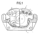
- a generic floating caliper partial brake disc brake has a floating U-shaped floating caliper 1 made of cast aluminum, which is slidably mounted on a brake carrier 2 by means of bolt guides 3.
- the floating caliper 1 has a saddle bridge 4, which axially spans two brake shoes 5, 6 and a brake disk, not shown.
- Six steel bolts 7 are arranged axially within the saddle bridge 4, each having a head section 8, a central section 9 and an end section 10.
- the end section 10 is provided with a screw thread.
- the saddle bridge 4 has cutouts 11 through which the middle sections 9 extend.
- the bolts 7 are positively connected to the floating saddle 1.
- the end section 10 can either, as shown in FIG.
- the floating caliper 1 is on its outer axial side on a radially outer narrow side 15 of the Brake shoe 5 supported.
- the floating caliper 1 has recesses 16 at the points provided for support, through which a bolt 7 runs.
- the bolt 7 lies with its central portion 9 on the surface 15 of the brake shoe 5, whereby the floating caliper 1 is supported.
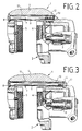
- FIGS. 7 to 11 show a further embodiment of a floating caliper partial brake disc brake according to the invention.
- a floating caliper 1 made of cast aluminum is in turn guided axially displaceably by means of bolt guides 3 on a brake carrier 2.
- the saddle bridge 4 extends in the axial direction over the outer edge 17 of the brake disk and over the brake shoes 5, 6 arranged on both sides of the brake disk.
- the floating saddle 1 is provided with reinforcing elements in the area of the saddle bridge 4.
- Serving as reinforcing elements are twelve sleeves 18 which are designed as thick-walled tubes and are arranged in two rows one above the other and offset from one another. As can best be seen in FIGS. 9 or 10, the sleeves 18 are inserted into blind bores 20 of the saddle bridge 4.
- the saddle bridge 4 is reinforced by the sleeves 20 only when subjected to bending stress.
- the sleeves 18 essentially do not provide any reinforcement, since the sleeves 18 in the bores 20 have essentially no axial prestress.
- the sleeves 18 are made of steel and their surfaces are galvanized and nickel-plated.
- the air contained in the blind bores 20 can escape through the inner cavity 21 of the sleeves 18.
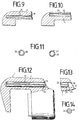
- 11 shows a sleeve 18 and a modified sleeve 19 in cross section.
- the sleeve 19 also has a slot 22 which extends over the entire length of the sleeve 19 extends.
- the slotted sleeves 19 have a higher elasticity than the sleeves 18.
- the sleeves 19 always lie with their peripheral surfaces firmly against the inner surfaces of the bores 20 and thus ensure a reliable clamping fit of the sleeves 19 in the bores 20. Even when there are expand the material of the sleeve 19 and the material of the floating saddle 1 differently under the action of heat.
- massive cylindrical pins 23 are provided as reinforcing elements, which are also pressed into blind bores 20.
- the pins 23 are provided with a groove 24 running over their entire length. If the press fit of the pins 23 in the bores 20 should loosen due to strong temperature changes, a securing according to FIG. 13 is recommended.
- the pin 23 is made somewhat shorter here, so that its end 25 can be completely sunk into the bore 20. After the pin 23 has been pressed in, the opening 27 of the bore 20 is slightly reduced by means of a deformation 26, so that the pin 23, even if it should loosen, cannot slip out of the bore 20.
- FIGS. 15 and 16 Another embodiment of the invention is shown in FIGS. 15 and 16.
- the saddle bridge 4 of the floating saddle 1 is in turn provided with blind bores 20 which, in principle, do not differ in their arrangement, design and method of manufacture from the blind bores 20 of the preceding exemplary embodiments.
- screw bolts 28 made of steel are provided as reinforcing elements, which have a thread structure over their entire screw-in length, through which a thread is cut into the originally smooth bores 20 when the screw bolts 28 are screwed in.
- the screw bolts 28 therefore have a thread structure suitable for forming a thread.
- the screw bolts 28 do not generate any axial preload here either. In this, too, they differ from the steel bolts 7 of the first exemplary embodiment.
- the steel bolts as shown in FIG. 15, can be provided with an internal hexagon 29 or, as shown in FIG. 16, with an external hexagon 30 or a star-shaped screw head 31.
- FIGS. 17 and 18 A further variant of a floating caliper partial lining disc brake according to the invention, which can be implemented in connection with all of the preceding exemplary embodiments, is shown in FIGS. 17 and 18.
- the floating caliper 1 has a leg 32 adjoining the caliper bridge 4, which extends essentially parallel to the brake disc.
- the leg 32 is used to press the brake shoe 5 against the brake disc.
- four reinforcement elements in the form of sleeves 33 are provided, of which only the two sleeves arranged on the left side of the leg 32 are shown in FIG. 17 33 are visible.
- the sleeves 33 are inserted into blind bores 34.
- the reinforcing elements can also be designed in accordance with the embodiments shown in FIGS. 11 to 16.
- the brake shoe 5 here consists of a back plate 35 which carries a friction lining (not shown) and is provided with hammer-head-shaped projections 36 on its sides lying in the circumferential direction of the brake disc.
- the floating saddle 1 is supported in the area of its saddle bridge 4 on a narrow side of the projections 36. Since the floating caliper 1 is made of cast aluminum and the back plate 35 is made of steel, problems arise when these two parts come into direct contact. Due to the different electrochemical potentials of the different metals, corrosion occurs increasingly at a contact point.
- a notch 37 is inserted into the floating saddle 1 in the area of the contact point and has a relatively large, essentially square head.
- the notch nail 37 is made of steel and has contact surfaces 38, 39 which are intended for contact with corresponding surfaces of the projections 36.
- the head of the notch nail extends in the circumferential direction and in the radial direction beyond the side surfaces of the floating saddle, so that the material of the floating saddle (cast aluminum) cannot come into contact with the back plate 35. Since only the steel contact surfaces 38, 39 of the notched nail 37 come into contact with the back plate 35, the corrosion problems mentioned do not occur.
Landscapes
- Engineering & Computer Science (AREA)
- General Engineering & Computer Science (AREA)
- Mechanical Engineering (AREA)
- Braking Arrangements (AREA)
Abstract
Claims (17)
- Frein à disque à garnitures partielles à étrier flottant, comprenant un étrier flottant (1), qui est adapté à des garnitures de frein (5, 6) disposées, en vue de leur serrage, de part et d'autre d'un disque de frein, cet étrier flottant (1) entourant en U les garnitures de frein (5, 6) et comportant un pont d'étrier (4) qui recouvre axialement le bord radialement extérieur du disque de frein et les garniture de frein (5, 6) et qui transmet la force d'application du frein servant au serrage des garnitures de frein (5, 6), et aumoins un élément de renfort, notamment une pièce filetée, qui est disposé à l'intérieur du pont d'étrier (4) d'une manière pratiquement parallèle à l'axe du disque de frein, I'étrier flottant (1) étant pour l'essentiel formé d'une pièce moulée en aluminium et le ou les éléments de renfort étant en une matière à haute résistance, caractérisé en ce que les éléments de renfort prévus pour accroître la rigidité à la flexion de l'étrier flottant (1) sont formés de broches (23), manchons (18,19) ou pièces filetées (7, 28), pratiquement cylindriques, qui sont emboîtés ou vissés, pratiquement sans précontrainte axiale, dans des évidements (11) ou des alésages (20) qui s'étendent d'une manière pratiquement parallèle à l'axe du disque de frein, une section centrale (9) des éléments de renfort étant disposée au voisinage direct du bord radialement extérieur du disque de frein.
- Frein à disque selon la revendication 1, caractérisé en ce que les éléments de renfort (7, 18, 19, 23, 28) sont en acier.
- Frein à disque selon la revendication 2, caractérisé en ce que les surfaces des éléments de renfort (7, 18, 19, 23, 28) sont zinguées et/ou nickelées.
- Frein à disque selon l'une des revendications 1 à 3, caractérisé en ce que les éléments de renfort sont des pièces filetées (7) du commerce, en acier, qui, à l'endroit de leurs deux sections d'extrémité (8, 10), sont solidaires de l'étrier flottant (1) par complémentarité de formes.
- Frein à disque selon l'une des revendications précédentes, caractérisé en ce qu'à l'emplacement ou aux emplacements prévus pour l'appui, I'étrier flottant (1) comporte des évidements (16) dans lesquels une pièce filetée (7) s'étend et en ce que la pièce filetée (7) est en appui sur un petit côté radialement extérieur (15) d'une garniture de frein (5).
- Frein à disque selon la revendication 5, caractérisé en ce qu'à l'emplacement prévu pour l'appui de l'étrier flottant (1), le petit côté radialement extérieur (15) de la garniture de frein (5) est adapté, de préférence en forme d'arc, à la pièce filetée (7) en appui.
- Frein à disque selon l'une des revendications 1 à 3, caractérisé en ce que les éléments de renfort sont réalisées sous la forme de manchons cylindriques creux (18,19) ou tubes.
- Frein à disque selon la revendication 7, caractérisé en ce que les manchons (19) ou tubes comportent une fente (22) continue suivant la direction longitudinale.
- Frein à disque selon l'une des revendications 1 à 3, caractérisé en ce que les éléments de renfort sont réalisés sous la forme de broches cylindriques pleines (23).
- Frein à disque selon l'une des revendications 7 à 9, caractérisé en ce que les éléments de renfort (18,19, 23) sont engagés à force dans les alésages (20) du pont d'étrier (4).
- Frein à disque selon l'une des revendications 7 à 10, caractérisé en ce que les alésages du pont d'étrier (4) sont des alésages borgnes (20).
- Frein à disque selon l'une des revendications 9 à 11, caractérisé en ce que les broches (23) sont pourvues d'une rainure (24) s'étendant sur toute leur longueur.
- Frein à disque selon la revendication 11, caractérisé en ce que les éléments de renfort (23) sont immobilisés au moyen d'une partie déformée (26) de l'extrémité ouverte (27) des alésages borgnes (20).
- Frein à disque selon l'une des revendications 7 à 13, caractérisé en ce qu'en tout, douze éléments de renfort (18, 19, 23) sont disposés dans douze alésages (20) du pont d'étrier (4), d'une manière symétrique vis-à-vis du milieu du frein, en deux rangées situées l'une au-dessus de l'autre vis-à-vis de l'axe du disque de frein et comportant chacune six éléments de renfort (18, 19, 23), et d'une manière décalée les uns vis-à-vis des autres.
- Frein à disque selon les revendications 7 à 14, caractérisé en ce que d'autres alésages (34), dans lesquels d'autres éléments de renfort (33) sont emboîtés, sont ménagés dans une aile (32) de l'étrier flottant (1) qui est voisine du pont d'étrier (4), ces autres éléments de renfort (33) s'étendant d'une manière pratiquement parallèle au disque de frein et d'une manière pratiquement perpendiculaire au pont d'étrier (4).
- Frein à disque selon l'une des revendications 1 à 3, caractérisé en ce que les pièces filetées (28) ont, sur toute la longueur suivant laquelle elles sont vissées, une structure filetée au moyen de laquelle, lors du vissage des pièces filetées (28), un taraudage est taillé dans les alésages (20) qui sont initialement lisses.
- Garniture de frein pour frein à disque selon l'une des revendications 5 et 6, comprenant une plaquette de support qui porte une garniture de friction et comporte deux parties en saillie, en forme de tête de marteau, qui font saillie latéralement sur le côté de la plaquette de support suivant une direction circonférentielle et qui sont destinées à la transmission des forces de frottement à un support de frein (2) et à l'appui radial de l'étrier flottant (1) sur le support de frein (2), caractérisé en ce que les petits côtés radialement extérieurs (15) des parties en saillie qui font face à l'étrier flottant (1) sont pourvus d'évidements concaves, pratiquement cylindriques, sur la surface de chacun desquels peut prendre appui une pièce filetée (7) solidaire de l'étrier flottant (1).
Applications Claiming Priority (5)
| Application Number | Priority Date | Filing Date | Title |
|---|---|---|---|
| DE4110870 | 1991-04-04 | ||
| DE4110870 | 1991-04-04 | ||
| DE4202394A DE4202394A1 (de) | 1991-04-04 | 1992-01-29 | Schwimmsattel-teilbelagscheibenbremse mit einem bremsengehaeuse aus leichtmetall |
| DE4202394 | 1992-01-29 | ||
| PCT/EP1992/000718 WO1992017712A1 (fr) | 1991-04-04 | 1992-04-01 | Frein a disque a garniture partielle a etrier flottant ayant un boitier en metal leger |
Publications (2)
| Publication Number | Publication Date |
|---|---|
| EP0577671A1 EP0577671A1 (fr) | 1994-01-12 |
| EP0577671B1 true EP0577671B1 (fr) | 1995-10-11 |
Family
ID=25902522
Family Applications (1)
| Application Number | Title | Priority Date | Filing Date |
|---|---|---|---|
| EP92907303A Expired - Lifetime EP0577671B1 (fr) | 1991-04-04 | 1992-04-01 | Frein a disque a garniture partielle a etrier flottant ayant un boitier en metal leger |
Country Status (4)
| Country | Link |
|---|---|
| US (1) | US5472068A (fr) |
| EP (1) | EP0577671B1 (fr) |
| DE (2) | DE4202394A1 (fr) |
| WO (1) | WO1992017712A1 (fr) |
Families Citing this family (33)
| Publication number | Priority date | Publication date | Assignee | Title |
|---|---|---|---|---|
| DE4236683C2 (de) * | 1992-10-30 | 2003-07-24 | Continental Teves Ag & Co Ohg | Schwimmsattel-Teilbelagscheibenbremse |
| CH686797A5 (de) * | 1993-02-18 | 1996-06-28 | Alusuisse Lonza Services Ag | Schwimm- oder Faustsattelzange. |
| US5394963A (en) * | 1993-06-18 | 1995-03-07 | The Budd Company | Composite cast brake caliper |
| DE4334839A1 (de) * | 1993-10-13 | 1995-04-20 | Teves Gmbh Alfred | Schwimmsattel-Scheibenbremse |
| WO1996025608A1 (fr) * | 1995-02-15 | 1996-08-22 | Itt Automotive Europe Gmbh | Frein a disque de realisation legere |
| US5788341A (en) | 1995-06-06 | 1998-08-04 | Itt Automotive Electrical Systems, Inc. | Vehicle brake |
| DE19607056A1 (de) * | 1996-02-24 | 1997-08-28 | Teves Gmbh Alfred | Festsattelbremse mit zugehörigen Bremsbelägen |
| DE19622209A1 (de) * | 1996-06-03 | 1997-12-04 | Teves Gmbh Alfred | Teilbelag-Scheibenbremse |
| GB9625862D0 (en) * | 1996-12-12 | 1997-01-29 | T & N Technology Ltd | Disc brake |
| US6244391B1 (en) * | 1996-12-12 | 2001-06-12 | Federal-Mogul Technology Limited | Disc brake system with ABS |
| US6247560B1 (en) | 1996-12-12 | 2001-06-19 | Federal-Mogul Technology Limited | Slidable brake disc system |
| US6223863B1 (en) | 1996-12-12 | 2001-05-01 | Federal-Mogul Technology Limited | Disc brake suspension for improved turning circle |
| DE19652123A1 (de) * | 1996-12-14 | 1998-06-18 | Teves Gmbh Alfred | Bremssattel, insbesondere für Kraftfahrzeuge |
| IT1296104B1 (it) * | 1997-11-12 | 1999-06-09 | Freni Brembo Spa | Freno a disco particolarmente per autoveicoli |
| US6000506A (en) * | 1998-02-23 | 1999-12-14 | General Motors Corporation | Disc brake caliper |
| WO2001094804A1 (fr) * | 2000-06-07 | 2001-12-13 | Lucas Automotive Gmbh | Etrier flottant pour frein a disque, et frein a disque |
| SE519618C2 (sv) * | 2001-07-13 | 2003-03-18 | Volvo Lastvagnar Ab | Skivbroms för landfordon |
| SE523555C2 (sv) * | 2001-09-07 | 2004-04-27 | Haldex Brake Prod Ab | Modulformad skrivbroms för ett fordon |
| US6719104B1 (en) * | 2001-12-28 | 2004-04-13 | Kelsey-Hayes Company | Composite caliper for a disc brake assembly and method for producing same |
| US7168529B2 (en) * | 2003-09-24 | 2007-01-30 | Kelsey-Hayes Company | Brake caliper for disc brake assembly and method and apparatus for producing same |
| US8997945B1 (en) * | 2003-09-24 | 2015-04-07 | Kelsey-Hayes Company | Brake caliper for disc brake assembly and method and apparatus for producing same |
| JP2006071041A (ja) * | 2004-09-03 | 2006-03-16 | Honda Motor Co Ltd | 鞍乗り型不整地走行車両のブレーキキャリパ構造 |
| US7493482B2 (en) * | 2005-12-21 | 2009-02-17 | Caterpillar Inc. | Self-configurable information management system |
| US7331430B2 (en) * | 2006-01-05 | 2008-02-19 | Delphi Technologies, Inc. | Multi-disc brake with fixed center brake pad assembly |
| DE102006003748B4 (de) | 2006-01-26 | 2017-01-26 | Knorr-Bremse Systeme für Nutzfahrzeuge GmbH | Scheibenbremse, insbesondere für ein Nutzfahrzeug |
| DE102007051556A1 (de) * | 2007-10-29 | 2009-04-30 | Robert Bosch Gmbh | Selbstverstärkende Scheibenbremse |
| DE102007054759A1 (de) * | 2007-11-16 | 2009-05-28 | Knorr-Bremse Systeme für Nutzfahrzeuge GmbH | Bremssattel einer Scheibenbremse |
| PE20161551A1 (es) | 2009-09-03 | 2017-01-18 | Pfizer Vaccines Llc | Vacuna de pcsk9 |
| TW201305460A (zh) * | 2011-06-21 | 2013-02-01 | Cwd Llc | 具有交叉加強元件之單塊制動器卡鉗 |
| CA2781540A1 (fr) * | 2012-06-26 | 2013-12-26 | Ray Arbesman | Plaque de support pour frein a chanfrein a gradins |
| CN105179525A (zh) * | 2015-10-22 | 2015-12-23 | 王宪立 | 一种联合收割机液压制动装置 |
| CN106224386B (zh) * | 2016-08-26 | 2019-09-06 | 洛阳轴承研究所有限公司 | 一种轴承及其保持架 |
| US9989112B1 (en) * | 2017-02-24 | 2018-06-05 | Akebono Brake Industry Co., Ltd | Caliper housing having a mass damper |
Family Cites Families (23)
| Publication number | Priority date | Publication date | Assignee | Title |
|---|---|---|---|---|
| DE1286845B (de) * | 1966-06-30 | 1969-01-09 | Heinkel Ag Ernst | Einteiliger U-foermiger Bremssattel fuer eine Teilbelagscheibenbremse |
| DE1600139A1 (de) * | 1966-09-14 | 1970-02-05 | Teves Gmbh Alfred | Bremsgehaeuse fuer Scheibenbremsen |
| DE1935863A1 (de) * | 1969-07-15 | 1971-01-28 | Teves Gmbh Alfred | Vorrichtung zur Halterung und Fuehrung der Bremsbacken von Teilbelagsscheibenbremsen |
| US3895693A (en) * | 1970-02-12 | 1975-07-22 | Rene Lucien | Disc-brakes with graphite friction linings |
| JPS5316463B2 (fr) * | 1973-02-16 | 1978-06-01 | ||
| US3887045A (en) * | 1974-04-12 | 1975-06-03 | Gen Motors Corp | Disc brake caliper assembly and method |
| JPS536927Y2 (fr) * | 1974-07-19 | 1978-02-22 | ||
| DE2533058A1 (de) * | 1975-07-24 | 1977-02-10 | Buderus Eisenwerk | Gegossenes werkstueck |
| GB1567905A (en) * | 1976-01-17 | 1980-05-21 | Girling Ltd | Disc brakes |
| JPS5597536A (en) * | 1979-01-22 | 1980-07-24 | Akebono Brake Ind Co Ltd | Caliper for disk brake |
| GB2060093B (en) * | 1979-07-10 | 1984-01-04 | Akebono Brake Ind | Disc brake |
| DE2950660A1 (de) * | 1979-12-15 | 1981-07-02 | Alfred Teves Gmbh, 6000 Frankfurt | Bremssattel fuer eine teilbelag-scheibenbremse |
| DE3014057A1 (de) * | 1980-04-11 | 1981-10-15 | Alfred Teves Gmbh, 6000 Frankfurt | Bremsbackenhalterung fuer eine teilbelagscheibenbremse, insbesondere fuer kraftfahrzeuge |
| JPS5783733A (en) * | 1980-11-14 | 1982-05-25 | Akebono Brake Ind Co Ltd | Caliper for disc brake |
| GB2087490A (en) * | 1980-11-14 | 1982-05-26 | Automotive Prod Co Ltd | Disc brake calipers |
| FR2506413B1 (fr) * | 1981-05-21 | 1986-08-29 | Valeo | Frein pour vehicule automobile, en particulier pour vehicule tout terrain |
| JPS59101022U (ja) * | 1982-12-27 | 1984-07-07 | トヨタ自動車株式会社 | ブ−ツプロテクタ付デイスクブレ−キ |
| DE3344493A1 (de) * | 1983-12-09 | 1985-06-20 | Klaue, Hermann, Dr.-Ing., 3302 Cremlingen | Aussen geschlossenes bremsgehaeuse fuer vollbelagscheibenbremsen, insbesondere fuer kraftfahrzeuge |
| DE3438142A1 (de) * | 1984-10-18 | 1986-04-24 | Hermann Dr.-Ing. 3302 Cremlingen Klaue | Bremsgehaeuse fuer vollbelagscheibenbremsen, insbesondere fuer kraftfahrzeuge |
| GB8508957D0 (en) * | 1985-04-04 | 1985-05-09 | Alexander Controls Ltd | Disc brakes |
| DE3616634A1 (de) * | 1986-05-16 | 1987-11-19 | Teves Gmbh Alfred | Scheibenbremse, insbesondere fuer kraftfahrzeuge |
| JPS6246034A (ja) * | 1986-07-31 | 1987-02-27 | Nissin Kogyo Kk | デイスクブレ−キ |
| JP2724757B2 (ja) * | 1989-09-13 | 1998-03-09 | 曙ブレーキ工業株式会社 | ディスクブレーキ装置 |
-
1992
- 1992-01-29 DE DE4202394A patent/DE4202394A1/de not_active Withdrawn
- 1992-04-01 US US08/129,046 patent/US5472068A/en not_active Expired - Fee Related
- 1992-04-01 WO PCT/EP1992/000718 patent/WO1992017712A1/fr not_active Ceased
- 1992-04-01 DE DE59204005T patent/DE59204005D1/de not_active Expired - Fee Related
- 1992-04-01 EP EP92907303A patent/EP0577671B1/fr not_active Expired - Lifetime
Also Published As
| Publication number | Publication date |
|---|---|
| WO1992017712A1 (fr) | 1992-10-15 |
| DE4202394A1 (de) | 1992-10-08 |
| DE59204005D1 (de) | 1995-11-16 |
| US5472068A (en) | 1995-12-05 |
| EP0577671A1 (fr) | 1994-01-12 |
Similar Documents
| Publication | Publication Date | Title |
|---|---|---|
| EP0577671B1 (fr) | Frein a disque a garniture partielle a etrier flottant ayant un boitier en metal leger | |
| EP2997278B1 (fr) | Frein à disque à étrier d'un véhicule, en particulier d'un véhicule utilitaire, et ressort de retenue d'un tel frein | |
| EP2997277B1 (fr) | Frein à disque à étrier d'un véhicule, en particulier d'un véhicule utilitaire, et ressort de retenue d'un tel frein | |
| EP2252805B1 (fr) | Frein à disque garantissant un montage avec orientation correcte des garnitures de frein | |
| WO1992013210A1 (fr) | Plaquette pour freins a disque | |
| EP1898115A1 (fr) | Frein à disque de véhicule | |
| DE3017307C2 (de) | Führung für die Tragplatten von Bremsbelägen einer Teilbelagscheibenbremse | |
| DE69011279T2 (de) | Räder mit eingebauten Bremsscheiben. | |
| EP2895760A1 (fr) | Frein à disque à commande pneumatique ou électromécanique | |
| DE2916244A1 (de) | Schwimmsattel-teilbelag-scheibenbremse, insbesondere fuer kraftfahrzeuge | |
| DE102016103396B4 (de) | Bremsbelag einer Scheibenbremse und Bremsbelagsatz | |
| DE8519567U1 (de) | Scheibenbremse mit Bremssattel und durch Haken im Bremssattel befestigten Bremsbelägen | |
| DE60211742T2 (de) | Scheibenbremssattel für fahrzeuge | |
| EP0597893B1 (fr) | Frein a disque a etrier flottant a agencement confortable des segments | |
| DE2742319A1 (de) | Scheibenbremse fuer fahrzeuge | |
| DE60208085T2 (de) | Stopper für schwimsattel einer bremsscheibe | |
| WO1992017713A1 (fr) | Frein a disque a garniture partielle et a etrier fixe | |
| DE3036985C2 (fr) | ||
| DE102020100139A1 (de) | Bremsbelag für eine Scheibenbremse eines Schienenfahrzeugs und Scheibenbremse | |
| EP3855039B1 (fr) | Étrier de frein en fonte | |
| EP1815158B1 (fr) | Disque de frein, en particulier pour vehicules automobiles | |
| DE2726741C3 (de) | Bremsscheibe | |
| EP3199828B1 (fr) | Fixation de garniture de frein à disque de véhicule et serre-flan pour la fixation des garnitures de frein | |
| DE3347387C2 (de) | Schwimmsattel-Scheibenbremse | |
| DE102006034766B3 (de) | Scheibenbremse, insbesondere für ein Nutzfahrzeug sowie Bremsbelag für eine Scheibenbremse |
Legal Events
| Date | Code | Title | Description |
|---|---|---|---|
| PUAI | Public reference made under article 153(3) epc to a published international application that has entered the european phase |
Free format text: ORIGINAL CODE: 0009012 |
|
| 17P | Request for examination filed |
Effective date: 19930922 |
|
| AK | Designated contracting states |
Kind code of ref document: A1 Designated state(s): DE FR IT |
|
| 17Q | First examination report despatched |
Effective date: 19940617 |
|
| ITF | It: translation for a ep patent filed | ||
| GRAA | (expected) grant |
Free format text: ORIGINAL CODE: 0009210 |
|
| AK | Designated contracting states |
Kind code of ref document: B1 Designated state(s): DE FR IT |
|
| REF | Corresponds to: |
Ref document number: 59204005 Country of ref document: DE Date of ref document: 19951116 |
|
| ET | Fr: translation filed | ||
| PLBE | No opposition filed within time limit |
Free format text: ORIGINAL CODE: 0009261 |
|
| 26N | No opposition filed | ||
| PGFP | Annual fee paid to national office [announced via postgrant information from national office to epo] |
Ref country code: FR Payment date: 19990419 Year of fee payment: 8 |
|
| PGFP | Annual fee paid to national office [announced via postgrant information from national office to epo] |
Ref country code: DE Payment date: 20000415 Year of fee payment: 9 |
|
| PG25 | Lapsed in a contracting state [announced via postgrant information from national office to epo] |
Ref country code: FR Free format text: LAPSE BECAUSE OF NON-PAYMENT OF DUE FEES Effective date: 20001229 |
|
| REG | Reference to a national code |
Ref country code: FR Ref legal event code: ST |
|
| PG25 | Lapsed in a contracting state [announced via postgrant information from national office to epo] |
Ref country code: DE Free format text: LAPSE BECAUSE OF NON-PAYMENT OF DUE FEES Effective date: 20020201 |
|
| PG25 | Lapsed in a contracting state [announced via postgrant information from national office to epo] |
Ref country code: IT Free format text: LAPSE BECAUSE OF NON-PAYMENT OF DUE FEES Effective date: 20050401 |