EP0577700B1 - Accessoire pour chargeuse sur roues - Google Patents
Accessoire pour chargeuse sur roues Download PDFInfo
- Publication number
- EP0577700B1 EP0577700B1 EP92908127A EP92908127A EP0577700B1 EP 0577700 B1 EP0577700 B1 EP 0577700B1 EP 92908127 A EP92908127 A EP 92908127A EP 92908127 A EP92908127 A EP 92908127A EP 0577700 B1 EP0577700 B1 EP 0577700B1
- Authority
- EP
- European Patent Office
- Prior art keywords
- accessory
- bucket
- wheel loader
- fastened
- support
- Prior art date
- Legal status (The legal status is an assumption and is not a legal conclusion. Google has not performed a legal analysis and makes no representation as to the accuracy of the status listed.)
- Expired - Lifetime
Links
Images

Classifications
-
- E—FIXED CONSTRUCTIONS
- E02—HYDRAULIC ENGINEERING; FOUNDATIONS; SOIL SHIFTING
- E02F—DREDGING; SOIL-SHIFTING
- E02F3/00—Dredgers; Soil-shifting machines
- E02F3/04—Dredgers; Soil-shifting machines mechanically-driven
- E02F3/28—Dredgers; Soil-shifting machines mechanically-driven with digging tools mounted on a dipper- or bucket-arm, i.e. there is either one arm or a pair of arms, e.g. dippers, buckets
- E02F3/36—Component parts
- E02F3/38—Cantilever beams, i.e. booms;, e.g. manufacturing processes, forms, geometry or materials used for booms; Dipper-arms, e.g. manufacturing processes, forms, geometry or materials used for dipper-arms; Bucket-arms
- E02F3/382—Connections to the frame; Supports for booms or arms
-
- E—FIXED CONSTRUCTIONS
- E02—HYDRAULIC ENGINEERING; FOUNDATIONS; SOIL SHIFTING
- E02F—DREDGING; SOIL-SHIFTING
- E02F3/00—Dredgers; Soil-shifting machines
- E02F3/04—Dredgers; Soil-shifting machines mechanically-driven
- E02F3/28—Dredgers; Soil-shifting machines mechanically-driven with digging tools mounted on a dipper- or bucket-arm, i.e. there is either one arm or a pair of arms, e.g. dippers, buckets
-
- E—FIXED CONSTRUCTIONS
- E02—HYDRAULIC ENGINEERING; FOUNDATIONS; SOIL SHIFTING
- E02F—DREDGING; SOIL-SHIFTING
- E02F3/00—Dredgers; Soil-shifting machines
- E02F3/04—Dredgers; Soil-shifting machines mechanically-driven
- E02F3/28—Dredgers; Soil-shifting machines mechanically-driven with digging tools mounted on a dipper- or bucket-arm, i.e. there is either one arm or a pair of arms, e.g. dippers, buckets
- E02F3/34—Dredgers; Soil-shifting machines mechanically-driven with digging tools mounted on a dipper- or bucket-arm, i.e. there is either one arm or a pair of arms, e.g. dippers, buckets with bucket-arms, i.e. a pair of arms, e.g. manufacturing processes, form, geometry, material of bucket-arms directly pivoted on the frames of tractors or self-propelled machines
- E02F3/3405—Dredgers; Soil-shifting machines mechanically-driven with digging tools mounted on a dipper- or bucket-arm, i.e. there is either one arm or a pair of arms, e.g. dippers, buckets with bucket-arms, i.e. a pair of arms, e.g. manufacturing processes, form, geometry, material of bucket-arms directly pivoted on the frames of tractors or self-propelled machines and comprising an additional linkage mechanism
- E02F3/3411—Dredgers; Soil-shifting machines mechanically-driven with digging tools mounted on a dipper- or bucket-arm, i.e. there is either one arm or a pair of arms, e.g. dippers, buckets with bucket-arms, i.e. a pair of arms, e.g. manufacturing processes, form, geometry, material of bucket-arms directly pivoted on the frames of tractors or self-propelled machines and comprising an additional linkage mechanism of the Z-type
-
- E—FIXED CONSTRUCTIONS
- E02—HYDRAULIC ENGINEERING; FOUNDATIONS; SOIL SHIFTING
- E02F—DREDGING; SOIL-SHIFTING
- E02F3/00—Dredgers; Soil-shifting machines
- E02F3/04—Dredgers; Soil-shifting machines mechanically-driven
- E02F3/28—Dredgers; Soil-shifting machines mechanically-driven with digging tools mounted on a dipper- or bucket-arm, i.e. there is either one arm or a pair of arms, e.g. dippers, buckets
- E02F3/36—Component parts
- E02F3/3695—Arrangements for connecting dipper-arms to loaders or graders
Definitions
- the object of the invention is an accessory for a wheel loader, this accessory consists of a support equipped with fastening devices for fastening the accessory removably to the arms of the wheel loader, a set of booms fixed to the support, a bucket fixed so that it can be turned at the end of the set of booms and a hydraulic cylinder for moving the bucket.
- Wheel loaders generally have an ordinary bucket fixed to the arms of the vehicle. This bucket removes soil at building sites and/or loads it on to vehicles, but this type of bucket cannot be used for excavating.
- wheel loaders with different kinds of removably fastened accessories, for example, smoothers, forks, derricks or other such equipment.
- a dredger ladle has been fastened on to a wheel loader or similar working appliance.
- Accessories are special appliances, they are complicated in structure, they are often large in size and they require additions or changes in the structure of a wheel loader.
- fastening and unfastening of accessories is awkward and time consuming, another that accessories cannot be transported from one workplace to another on a wheel loader together with other kinds of accessories.
- the aim of the invention is to bring forward an accessory for a wheel loader, such that, by the use of this accessory, the above mentioned disadvantages may be avoided.
- one aim of the invention is to bring forward an accessory for a wheel loader such that with its assistance, the wheel loader can be quickly converted for different purposes.
- the aim of the invention is to bring forward such an accessory for a wheel loader which has a simple structure, is easily and quickly installed and removed and which can be carried attached onto the wheel loader.
- the aim of the invention is to bring forward an accessory, the use of which requires no alterations or additions to the structure of the wheel loader.
- the set of booms consists of a supporting beam which has been fastened at one end to the support and at the other end of which a removable bucket has been fastened and after unfastening, the bucket can be turned to another position. Since there is only one supporting beam in the appliance it has a simple structure and is small in size and it does not consist of many parts, making it favourable for manufacturing.
- the present-day accessories consist of two or more supporting beams or similar constructions and two or more hydraulic cylinders, which makes them large in size and complicated in structure.
- the accessory according to this invention can be easily and quickly removed and fastened in place.
- the bucket has been fastened to the end of the supporting beam so that it can be turned into another working position. In this way, the same accessory can be used both as a dredger ladle and, after unfastening and turning it, in a dipper position as a bucket loader for removing and/or loading of earth.
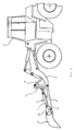
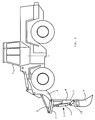
- the accessory consists of a support 2, set of booms 5 and a bucket 6.
- the support 2 can be removably fastened to a fastener 9 between the arms 4 of the wheel loader 1 by using fastening devices 3.
- the fastening devices consist of shoulders which have been placed at the top part of the support and pivot holes placed at the lower part of the support, by means of which the support and the whole accessory can be easily and simply fastened in its place resting on the fastener.
- also other kinds of fastening devices may be used.
- the set of booms 5 consists of a supporting beam 8 which has been fastened at one end to the support, and a hydraulic cylinder 7 which has been fastened at one end to the supporting beam.
- the bucket has been fastened reversibly to the end of the supporting beam 8.
- the hydraulic cylinder 7 has been articulated at one end to shafts 10, 11.
- the shaft 10 has been articulated at one end to the bucket and the shaft 11 has been fixed at one end to the supporting beam.
- the bucket can be unfastened and it can be turned to another working position by rotating it 180° relative to the longitudinal axis of the bucket. In this way, the bucket can be turned from the excavating position shown in the figures, to its second position, the dipper position.
- the hydraulic cylinder 7 has been arranged through shafts to turn the bucket during actual work.
- the hydraulic hoses (not shown in the figures) of the hydraulic cylinder have been connected with quick-attachment devices to the hydraulic system of the wheel loader, in which case the accessory can be steered from inside the cab of the wheel loader.
- the accessory can be quickly connected to the hydraulic system of the wheel loader or disconnected from it.
- the accessory can be turned into different positions by using the hydraulic cylinders of the arms of the wheel loader.
- the hydraulic cylinders of both the wheel loader and the accessory itself are being put to use so that the accessory can be turned, for example, from the basic position shown in figure 1 to the excavating position shown in figure 2.
- the accessory is easy to install and it requires no changes to be done in the structure of the wheel loader.
Landscapes
- Engineering & Computer Science (AREA)
- Mechanical Engineering (AREA)
- Mining & Mineral Resources (AREA)
- Civil Engineering (AREA)
- General Engineering & Computer Science (AREA)
- Structural Engineering (AREA)
- Shovels (AREA)
- Auxiliary Devices For Machine Tools (AREA)
- Constituent Portions Of Griding Lathes, Driving, Sensing And Control (AREA)
- Forklifts And Lifting Vehicles (AREA)
- Peptides Or Proteins (AREA)
- Medicines Containing Material From Animals Or Micro-Organisms (AREA)
Claims (2)
- Accessoire pour chargeuse sur roues comprenant un support (2) équipé d'un moyen de fixation (3) pour fixer l'accessoire de façon amovible au bras (4) de la chargeuse sur roues, un jeu de membrures fixé au support et comprenant un bras de support (8) fixé audit support à une extrémité, un godet (6) fixé de façon à pouvoir basculer à une extrémité du jeu de membrures et un cylindre hydraulique (7) pour déplacer le godet, ledit cylindre hydraulique étant fixé à une extrémité au bras de support et à l'autre extrémité de façon articulée à des tiges (10,11) dont l'une (10) est fixée audit godet (6) et l'autre (11) est fixée au bras de support (8), caractérisé en ce que le godet a été fixé de façon amovible à l'autre extrémité du bras de support (8) et peut être basculé d'une position d'excavation vers une position de drague après avoir été défait et vice-versa, de sorte que le même accessoire peut être utilisé aussi bien comme drague à cuillère ou comme chargeur à godet.
- Accessoire pour une chargeuse sur roues selon la revendication 1, caractérisé en ce que les tubes hydrauliques des cylindres hydrauliques (7) ont été fixés avec des moyens de fixation rapide au système hydraulique de la chargeuse sur roues.
Applications Claiming Priority (3)
| Application Number | Priority Date | Filing Date | Title |
|---|---|---|---|
| FI911637 | 1991-04-05 | ||
| FI911637A FI911637A7 (fi) | 1991-04-05 | 1991-04-05 | Pyöräkuormaajan lisälaite |
| PCT/FI1992/000101 WO1992017652A1 (fr) | 1991-04-05 | 1992-04-03 | Accessoire pour chargeuse sur roues |
Publications (2)
| Publication Number | Publication Date |
|---|---|
| EP0577700A1 EP0577700A1 (fr) | 1994-01-12 |
| EP0577700B1 true EP0577700B1 (fr) | 1996-06-05 |
Family
ID=8532249
Family Applications (1)
| Application Number | Title | Priority Date | Filing Date |
|---|---|---|---|
| EP92908127A Expired - Lifetime EP0577700B1 (fr) | 1991-04-05 | 1992-04-03 | Accessoire pour chargeuse sur roues |
Country Status (5)
| Country | Link |
|---|---|
| EP (1) | EP0577700B1 (fr) |
| AT (1) | ATE138997T1 (fr) |
| DE (1) | DE69211339T2 (fr) |
| FI (1) | FI911637A7 (fr) |
| WO (1) | WO1992017652A1 (fr) |
Families Citing this family (2)
| Publication number | Priority date | Publication date | Assignee | Title |
|---|---|---|---|---|
| DE10127048B4 (de) * | 2000-06-07 | 2009-04-16 | Eloy Ayala Ruiz | Verbesserte Lastfördermaschine mit Aushubzusatz und zugehörigem Fahrgestell |
| NL1025212C2 (nl) * | 2004-01-12 | 2005-07-13 | Jan Willem Josef Overbeek | Shovel hoogkiep adapter. |
Family Cites Families (4)
| Publication number | Priority date | Publication date | Assignee | Title |
|---|---|---|---|---|
| DE2315581B1 (de) * | 1973-03-29 | 1974-06-27 | International Harvester Co. Mbh, 4040 Neuss | Schaufellader |
| FR2268119B1 (fr) * | 1974-04-19 | 1976-10-08 | Poclain Sa | |
| SE437050B (sv) * | 1982-06-04 | 1985-02-04 | Ingemar Eriksson | Till en lastmaskin applicerbart grevaggregat for mindre grevarbeten |
| DE3546078A1 (de) * | 1985-12-24 | 1987-07-02 | Kramer Werke Gmbh | Radlader mit loeffelbagger |
-
1991
- 1991-04-05 FI FI911637A patent/FI911637A7/fi not_active Application Discontinuation
-
1992
- 1992-04-03 AT AT92908127T patent/ATE138997T1/de not_active IP Right Cessation
- 1992-04-03 DE DE69211339T patent/DE69211339T2/de not_active Expired - Fee Related
- 1992-04-03 WO PCT/FI1992/000101 patent/WO1992017652A1/fr not_active Ceased
- 1992-04-03 EP EP92908127A patent/EP0577700B1/fr not_active Expired - Lifetime
Also Published As
| Publication number | Publication date |
|---|---|
| DE69211339D1 (de) | 1996-07-11 |
| ATE138997T1 (de) | 1996-06-15 |
| WO1992017652A1 (fr) | 1992-10-15 |
| FI911637A0 (fi) | 1991-04-05 |
| DE69211339T2 (de) | 1997-01-16 |
| FI911637L (fi) | 1992-10-06 |
| EP0577700A1 (fr) | 1994-01-12 |
| FI911637A7 (fi) | 1992-10-06 |
Similar Documents
| Publication | Publication Date | Title |
|---|---|---|
| US7648326B2 (en) | Adapter faceplate | |
| US4200423A (en) | Storable boom attachment for a construction machine | |
| US5114299A (en) | Attachment for a prime mover | |
| US20010002086A1 (en) | Dual mode stabilizer for backhoe loaders and backhoe attachments | |
| US6098321A (en) | Bucket converter for an excavation bucket | |
| US5732488A (en) | Quick hitch assembly | |
| JP2674712B2 (ja) | 関節式の連結構造を有するクレーン型機械 | |
| US4960359A (en) | Demountable swing boom hoist for front end loaders | |
| US9945093B1 (en) | Excavator, excavator boom, stick object coupler receiver for the same and method of using the same | |
| US4225283A (en) | Backhoe bucket quick coupling | |
| US3977548A (en) | Cylinder attachment means for an excavator and method for using the same | |
| EP1127197B1 (fr) | Stabilisateur fonctionnant en deux modes pour chargeuse-pelleteuse et ses accessoires | |
| US6481949B1 (en) | Crane attachment for a front end loader | |
| US6059048A (en) | Implement mounting arrangement with independent lift-roll and pitch-yaw operability | |
| US6045320A (en) | Arm extension for a backhoe | |
| WO1992017652A1 (fr) | Accessoire pour chargeuse sur roues | |
| US20020102154A1 (en) | Mechanical linkage quick attachment system | |
| KR20210007658A (ko) | 회전 변환 멀티 링크 | |
| EP0875630A1 (fr) | Engin de construction | |
| US20230125572A1 (en) | Attachment for working machine | |
| SE8703622D0 (sv) | Vridbart redskapsfeste | |
| JPH1018336A (ja) | 作業機アタッチメントの簡易着脱装置 | |
| US12590435B2 (en) | Tractor attachment accessories | |
| KR19980074489A (ko) | 붐 선회 장치가 구비된 로우더 | |
| FI74098C (fi) | Redskapets faestanordning foer graev- och jordtransportmaskiner. |
Legal Events
| Date | Code | Title | Description |
|---|---|---|---|
| PUAI | Public reference made under article 153(3) epc to a published international application that has entered the european phase |
Free format text: ORIGINAL CODE: 0009012 |
|
| 17P | Request for examination filed |
Effective date: 19931015 |
|
| AK | Designated contracting states |
Kind code of ref document: A1 Designated state(s): AT BE CH DE DK ES FR GB IT LI NL SE |
|
| 17Q | First examination report despatched |
Effective date: 19950724 |
|
| GRAA | (expected) grant |
Free format text: ORIGINAL CODE: 0009210 |
|
| AK | Designated contracting states |
Kind code of ref document: B1 Designated state(s): AT BE CH DE DK ES FR GB IT LI NL SE |
|
| PG25 | Lapsed in a contracting state [announced via postgrant information from national office to epo] |
Ref country code: NL Free format text: LAPSE BECAUSE OF FAILURE TO SUBMIT A TRANSLATION OF THE DESCRIPTION OR TO PAY THE FEE WITHIN THE PRESCRIBED TIME-LIMIT Effective date: 19960605 Ref country code: LI Effective date: 19960605 Ref country code: IT Free format text: LAPSE BECAUSE OF FAILURE TO SUBMIT A TRANSLATION OF THE DESCRIPTION OR TO PAY THE FEE WITHIN THE PRE;WARNING: LAPSES OF ITALIAN PATENTS WITH EFFECTIVE DATE BEFORE 2007 MAY HAVE OCCURRED AT ANY TIME BEFORE 2007. THE CORRECT EFFECTIVE DATE MAY BE DIFFERENT FROM THE ONE RECORDED.SCRIBED TIME-LIMIT Effective date: 19960605 Ref country code: FR Effective date: 19960605 Ref country code: ES Free format text: THE PATENT HAS BEEN ANNULLED BY A DECISION OF A NATIONAL AUTHORITY Effective date: 19960605 Ref country code: DK Effective date: 19960605 Ref country code: CH Effective date: 19960605 Ref country code: BE Effective date: 19960605 Ref country code: AT Effective date: 19960605 |
|
| REF | Corresponds to: |
Ref document number: 138997 Country of ref document: AT Date of ref document: 19960615 Kind code of ref document: T |
|
| REF | Corresponds to: |
Ref document number: 69211339 Country of ref document: DE Date of ref document: 19960711 |
|
| EN | Fr: translation not filed | ||
| NLV1 | Nl: lapsed or annulled due to failure to fulfill the requirements of art. 29p and 29m of the patents act | ||
| REG | Reference to a national code |
Ref country code: CH Ref legal event code: PL |
|
| PLBE | No opposition filed within time limit |
Free format text: ORIGINAL CODE: 0009261 |
|
| 26N | No opposition filed | ||
| PGFP | Annual fee paid to national office [announced via postgrant information from national office to epo] |
Ref country code: GB Payment date: 20000330 Year of fee payment: 9 |
|
| PGFP | Annual fee paid to national office [announced via postgrant information from national office to epo] |
Ref country code: SE Payment date: 20000405 Year of fee payment: 9 |
|
| PGFP | Annual fee paid to national office [announced via postgrant information from national office to epo] |
Ref country code: DE Payment date: 20000630 Year of fee payment: 9 |
|
| PG25 | Lapsed in a contracting state [announced via postgrant information from national office to epo] |
Ref country code: GB Free format text: LAPSE BECAUSE OF NON-PAYMENT OF DUE FEES Effective date: 20010403 |
|
| PG25 | Lapsed in a contracting state [announced via postgrant information from national office to epo] |
Ref country code: SE Free format text: LAPSE BECAUSE OF NON-PAYMENT OF DUE FEES Effective date: 20010404 |
|
| GBPC | Gb: european patent ceased through non-payment of renewal fee |
Effective date: 20010403 |
|
| EUG | Se: european patent has lapsed |
Ref document number: 92908127.1 |
|
| PG25 | Lapsed in a contracting state [announced via postgrant information from national office to epo] |
Ref country code: DE Free format text: LAPSE BECAUSE OF NON-PAYMENT OF DUE FEES Effective date: 20020201 |