EP0577793B1 - Halterung für ein zielfernrohr - Google Patents
Halterung für ein zielfernrohr Download PDFInfo
- Publication number
- EP0577793B1 EP0577793B1 EP93901949A EP93901949A EP0577793B1 EP 0577793 B1 EP0577793 B1 EP 0577793B1 EP 93901949 A EP93901949 A EP 93901949A EP 93901949 A EP93901949 A EP 93901949A EP 0577793 B1 EP0577793 B1 EP 0577793B1
- Authority
- EP
- European Patent Office
- Prior art keywords
- bolt
- engaging elements
- mounting
- pair
- free end
- Prior art date
- Legal status (The legal status is an assumption and is not a legal conclusion. Google has not performed a legal analysis and makes no representation as to the accuracy of the status listed.)
- Expired - Lifetime
Links
Images


Classifications
-
- F—MECHANICAL ENGINEERING; LIGHTING; HEATING; WEAPONS; BLASTING
- F41—WEAPONS
- F41G—WEAPON SIGHTS; AIMING
- F41G11/00—Details of sighting or aiming apparatus; Accessories
- F41G11/001—Means for mounting tubular or beam shaped sighting or aiming devices on firearms
- F41G11/005—Mountings using a pivot point and an anchoring point
- F41G11/006—Mountings using a pivot point and an anchoring point the device being rotated in a horizontal plane
Definitions
- the invention relates to a holder for a rifle scope, especially for a handgun, with one on the Gun mountable support device and with a scope mountable support device attached to the support device is fixable, the support device and the Carrier each a pair of spaced apart Have engaging elements, the engaging elements one of the two pairs, changing their distance against the engagement elements of the second pair can be clamped.
- Such a scope holder is, for example US-A 2,942,346 or US-A 2,710,453.
- Both Rifle scope mounts show levers with the help of which Locking and release of the engagement elements can take place. The holding forces are relatively low because of one partially relaxed after releasing the lever Spring are applied.
- the invention has therefore set itself the task of a To create a mount for a scope that described Avoids and achieves the disadvantage of low holding forces this is due to the fact that the distance between the Engagement elements a toggle with a side protruding clamping handle is provided.
- the tensionable engaging elements are preferably on one common support body is provided, wherein an engagement element especially by the free end of a spring loaded Bolt is formed by means of the toggle lever is movable.
- that the toggle is articulated on a slider is from which a guide pin protrudes, on which the bolt is slidably disposed, between the slider and a compression spring is supported on the bolt.
- the bracing can center at the same time if the free end of the bolt tapers and that with the free end of the bolt cooperating engaging element the support device has a tapered depression.
- the recess is particularly conical and the free end of the bolt is rounded.
- FIG. 1 shows an exploded view of the scope holder
- Fig. 2 shows a detail of an attachment side of the Bracket
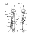
- Fig. 3 and 4 a first embodiment of the bracket in assembly and holding position
- Fig. 5 and 6 a second Version also in mounting and holding position.
- a rifle scope holder comprises a support device 1, the holes for mounting on the weapon, for example having.
- the engaging element 2 consists of a truncated cone that widens upwards and can be flattened on the front.
- the engaging element 3 points to a side facing the engagement element 2, extending perpendicular to the longitudinal direction End face a recess 7.
- the over the scope Brackets 8 to be fastened 4 also have a pair of engaging elements 5.6, which after insertion into the engagement elements 2, 3 of the first pair Connect the telescopic sight to the weapon detachably.
- For one Adjustment can engage the engaging element 3 of the first pair arranged on the support device 1 be. This has an undercut groove 10, which runs perpendicular to the longitudinal direction and into the one Wedge bar 9 of the engagement element 3 engages. The adjustment is possible via the indicated screw 11.
- the carrying device 4 has an elongated support body 12, at the first end of which the engagement element 5 in Form provided a half, frustoconical recess is.
- the carrier body 12 can thus be any Side pushed onto the engagement element 2 (Fig. 3.5) and then optionally rotated (Fig. 4).
- a pin 14 in the longitudinal direction is movable.
- the emerging from the recess 13 rounded end of the bolt 14 forms the second Engagement element 6 of the support device 4, which in the trough or recess 7 in the engagement element 3 can be inserted.
- the toggle lever 18 is mounted on the one hand in the carrier body 12 and on the other hand articulated on a slider 15 which in the recess 13 slidably and with a guide pin 17 is provided.
- the bolt 14 has a bore in which the guide pin 17 is held.
- a compression spring 16 is arranged, with a head of the guide pin in the expanded Part of the bolt hole serves as an abutment.
- the guide pin 17 is therefore preferably by one in the slider 15 inserted screw formed.
- the toggle lever 18 pivoted out, so that the distance between the two engaging elements 5,6 is small. It can either first the engaging element 5 on the engaging element 2 pushed (Fig.
Landscapes
- Engineering & Computer Science (AREA)
- General Engineering & Computer Science (AREA)
- Aiming, Guidance, Guns With A Light Source, Armor, Camouflage, And Targets (AREA)
- Telescopes (AREA)
Description
Claims (5)
- Halterung für ein Zielfernrohr, insbesondere für eine Handfeuerwaffe, mit einer auf der Waffe montierbaren Stützvorrichtung (1) und mit einer am Zielfernrohr montierbaren Tragvorrichtung (4), die an der Stützvorrichtung (1) fixierbar ist, wobei die Stützvorrichtung (1) und die Tragvorrichtung (4) je ein Paar von voneinander beabstandeten Eingriffselementen (2,3;5,6) aufweisen, wobei die Eingriffselemente (5,6) eines der beiden Paare unter Änderung ihres Abstandes gegen die Eingriffselemente (2,3) des zweiten Paares verspannbar sind, dadurch gekennzeichnet, daß zwischen den im Abstand veränderbaren Eingriffselementen (5,6) ein Kniehebel (18) mit einem seitlich abstehenden Spanngriff (19) vorgesehen ist.
- Halterung nach Anspruch 1, dadurch gekennzeichnet, daß das im Abstand veränderbare Paar von Eingriffselementen (5,6) an einem gemeinsamen Trägerkörper (12) vorgesehen ist.
- Halterung nach Anspruch 2, dadurch gekennzeichnet, daß am Trägerkörper (12) ein federbeaufschlagter, mittels des Kniehebels (18) verschiebbarer Bolzen (14) angeordnet ist, dessen freies Ende eines der beiden Eingriffselemente (6) bildet.
- Halterung nach Anspruch 3, dadurch gekennzeichnet, daß der Kniehebel (18) an einem Gleitstück (15) angelenkt ist, von dem ein Führungsstift (17) absteht, auf dem der Bolzen (14) gleitend angeordnet ist, wobei zwischen dem Gleitstück (15) und dem Bolzen (14) eine Druckfeder (16) abgestützt ist.
- Halterung nach Anspruch 3, dadurch gekennzeichnet, daß das freie Ende des Bolzens (14) sich verjüngt und das mit dem freien Ende des Bolzens (14) zusammenwirkende Eingriffselement (3) der Stützvorrichtung (1) eine sich verjüngende Vertiefung (7) aufweist.
Applications Claiming Priority (3)
| Application Number | Priority Date | Filing Date | Title |
|---|---|---|---|
| AT0014292A AT402564B (de) | 1992-01-29 | 1992-01-29 | Halterung für ein zielfernrohr |
| AT142/92 | 1992-01-29 | ||
| PCT/AT1993/000011 WO1993015371A1 (de) | 1992-01-29 | 1993-01-28 | Halterung für ein zielfernrohr |
Publications (2)
| Publication Number | Publication Date |
|---|---|
| EP0577793A1 EP0577793A1 (de) | 1994-01-12 |
| EP0577793B1 true EP0577793B1 (de) | 1998-07-15 |
Family
ID=3482643
Family Applications (1)
| Application Number | Title | Priority Date | Filing Date |
|---|---|---|---|
| EP93901949A Expired - Lifetime EP0577793B1 (de) | 1992-01-29 | 1993-01-28 | Halterung für ein zielfernrohr |
Country Status (6)
| Country | Link |
|---|---|
| US (1) | US5390419A (de) |
| EP (1) | EP0577793B1 (de) |
| AT (1) | AT402564B (de) |
| AU (1) | AU3337193A (de) |
| DE (1) | DE59308767D1 (de) |
| WO (1) | WO1993015371A1 (de) |
Families Citing this family (32)
| Publication number | Priority date | Publication date | Assignee | Title |
|---|---|---|---|---|
| FR2734629B1 (fr) * | 1995-05-23 | 1997-07-25 | Giat Ind Sa | Accessoire d'arme a feu portative |
| US5806228A (en) * | 1996-11-12 | 1998-09-15 | Martel; Phillip C. | Scope mount for the carrying handle of M-16 type rifles |
| US6629381B1 (en) | 1999-02-01 | 2003-10-07 | Da Keng | Reinforced firearm sight support ring |
| FR2813664B1 (fr) * | 2000-09-01 | 2003-03-21 | Michel Mangel | Dispositif de montage rotatif pour pose et depose de lunette de visee pour arme a feu |
| FI110285B (fi) * | 2001-03-05 | 2002-12-31 | Sako Oy | Kiikaritähtäimen pikakiinnitysjalka |
| US6594938B2 (en) * | 2001-09-26 | 2003-07-22 | John Wiley Horton | Front interfacing detachable scope mount |
| CA2537084C (en) * | 2003-07-28 | 2008-08-26 | Heckler & Koch Gmbh | Mounting device |
| US20060207156A1 (en) * | 2005-03-05 | 2006-09-21 | Larue Mark C | Mount for firearm sighting device having throw-lever clamp and lever safety latch |
| US7444776B2 (en) * | 2005-08-10 | 2008-11-04 | Steve Adams | Vertical lift mount apparatus for firearm accessories |
| US20070186459A1 (en) * | 2006-02-14 | 2007-08-16 | Horton John W | Front interfacing detachable scope mount |
| US7823316B2 (en) | 2007-01-12 | 2010-11-02 | American Defense Manufacturing, Llc | Adjustable gun rail lock |
| US20080168696A1 (en) * | 2007-01-12 | 2008-07-17 | William Orne | Gun Accessory Quick Lock System |
| US8578647B2 (en) | 2007-01-12 | 2013-11-12 | American Defense Manufacturing, Llc | Locking quick release clamp assembly |
| US20090038201A1 (en) * | 2007-08-06 | 2009-02-12 | Li-Der Cheng | Gun attachment mounting structure |
| US20090133311A1 (en) * | 2007-11-06 | 2009-05-28 | Hollenbach Ned J | Universal scope mounting system |
| US7971384B2 (en) * | 2009-01-12 | 2011-07-05 | Lippard Karl C | Interchangeable scope mount |
| DE102010005588A1 (de) * | 2009-12-22 | 2011-06-30 | Ziegler, Gerhard, 91166 | Zielfernrohrmontagesystem für eine Feuerwaffe |
| DE102010005589A1 (de) * | 2009-12-22 | 2011-06-30 | Ziegler, Gerhard, 91166 | Zielfernrohrmontagesystem |
| DE102010005590A1 (de) | 2009-12-22 | 2011-06-30 | Ziegler, Gerhard, 91166 | Zielfernrohrmontagesysstem mit Klemmmittel |
| WO2013173646A1 (en) * | 2012-05-16 | 2013-11-21 | Diffraction Ltd. | Kinematic mount |
| US10036614B1 (en) | 2017-01-28 | 2018-07-31 | AIM Sports Inc. | Quick release mechanisms to attach accessories to firearms |
| USD837329S1 (en) | 2017-01-28 | 2019-01-01 | AIM Sports Inc. | Quick release mechanism |
| USD837929S1 (en) | 2017-10-19 | 2019-01-08 | Bushnell Inc. | Scope mount |
| USD906469S1 (en) * | 2019-06-11 | 2020-12-29 | Timothy L. Coggins | Scope mount |
| EP3809093B1 (de) * | 2019-10-15 | 2022-05-04 | Daniel Dentler | Montagevorrichtung für ein zielfernrohr bei einer jagd- oder sportwaffe mit mindestens einem federnden stehbolzen |
| DE202021103809U1 (de) | 2021-07-16 | 2022-10-25 | Blaser Group Gmbh | Waffenmontage |
| DE102021118421A1 (de) | 2021-07-16 | 2023-01-19 | Blaser Group Gmbh | Waffenmontage |
| USD1010918S1 (en) * | 2021-12-13 | 2024-01-09 | Arisaka LLC | Mounting component of a pivoting flashlight mount |
| USD1010205S1 (en) * | 2022-06-13 | 2024-01-02 | Arisaka LLC | Mounting component of a pivoting flashlight mount |
| USD1015623S1 (en) * | 2022-06-13 | 2024-02-20 | Arisaka LLC | Mounting component of a pivoting flashlight mount |
| US12480744B2 (en) * | 2023-04-05 | 2025-11-25 | Strike IP, LLC | Firearm rotation mount for optics and accessories |
| CN116817677B (zh) * | 2023-05-23 | 2025-12-23 | 西安航天动力技术研究所 | 一种瞄准具与平台快速连接机构 |
Family Cites Families (16)
| Publication number | Priority date | Publication date | Assignee | Title |
|---|---|---|---|---|
| DE7038599U (de) * | 1971-03-25 | E Apel Feinmechanische Erzeugnisse | Zielfernrohrhalterung mit selbsttätig verriegelndem und wahlweise nachstellbarem Di ehbolzenverschluß | |
| CA651589A (en) * | 1962-11-06 | V. Dimick Joseph | Gun telescope mounting | |
| DE282874C (de) * | 1913-06-03 | |||
| US1144647A (en) * | 1914-06-02 | 1915-06-29 | Terje Aanensen Fidjeland | Mechanism for attaching sighting-telescopes to firearms. |
| US2450466A (en) * | 1947-01-06 | 1948-10-05 | Carlson Richard | Telescope mounting for guns |
| US2510289A (en) * | 1947-09-02 | 1950-06-06 | Earl L Livermore | Telescope mount |
| US2621410A (en) * | 1949-04-13 | 1952-12-16 | Bausch & Lomb | Gun telescope mounting |
| US2739384A (en) * | 1952-04-15 | 1956-03-27 | James A Chokae | Windage and elevation adjustable mount for telescopic gunsight |
| US2710453A (en) * | 1954-06-21 | 1955-06-14 | Beverly Bobby | Telescopic sight mounting for guns |
| US2836895A (en) * | 1955-12-13 | 1958-06-03 | Ernesto P Dillon | Telescopic sight mount for fire arms |
| US2942346A (en) * | 1958-02-18 | 1960-06-28 | Ernst Leitz Canada Ltd | Gun telescope mounting |
| US3153856A (en) * | 1961-12-14 | 1964-10-27 | Thomas R Felix | Telescope sight mount |
| US3205579A (en) * | 1963-11-04 | 1965-09-14 | Bausch & Lomb | Demountable gun telescope mounting |
| DE8312673U1 (de) * | 1983-04-29 | 1983-09-29 | Kepplinger, Johann, Ing., Kufstein | Zielfernrohrhalterung |
| CH666120A5 (de) * | 1984-02-09 | 1988-06-30 | Sig Schweiz Industrieges | Vorrichtung zur halterung einer zielvorrichtung auf einer handfeuerwaffe. |
| US5070637A (en) * | 1989-12-22 | 1991-12-10 | K. W. Thompson Tool Company, Inc. | Telescopic |
-
1992
- 1992-01-29 AT AT0014292A patent/AT402564B/de not_active IP Right Cessation
-
1993
- 1993-01-28 US US08/122,489 patent/US5390419A/en not_active Expired - Fee Related
- 1993-01-28 EP EP93901949A patent/EP0577793B1/de not_active Expired - Lifetime
- 1993-01-28 DE DE59308767T patent/DE59308767D1/de not_active Expired - Fee Related
- 1993-01-28 AU AU33371/93A patent/AU3337193A/en not_active Abandoned
- 1993-01-28 WO PCT/AT1993/000011 patent/WO1993015371A1/de not_active Ceased
Also Published As
| Publication number | Publication date |
|---|---|
| AU3337193A (en) | 1993-09-01 |
| ATA14292A (de) | 1996-10-15 |
| AT402564B (de) | 1997-06-25 |
| EP0577793A1 (de) | 1994-01-12 |
| WO1993015371A1 (de) | 1993-08-05 |
| US5390419A (en) | 1995-02-21 |
| DE59308767D1 (de) | 1998-08-20 |
Similar Documents
| Publication | Publication Date | Title |
|---|---|---|
| AT402564B (de) | Halterung für ein zielfernrohr | |
| EP0159007B1 (de) | Vorrichtung zum Einrichten einer Wirbelsäule | |
| DE3801103A1 (de) | Befestigungsvorrichtung fuer einstellbare frontblenden von schubladen | |
| EP1590618A1 (de) | Vorrichtung zur montage eines zielfernrohrs an einer waffe | |
| EP0267477A1 (de) | Befestigungsvorrichtung für einstellbare Frontblenden von Schubladen | |
| EP2956732B1 (de) | Universelle zielfernrohrmontage für handfeuerwaffen | |
| DE8704901U1 (de) | Vorrichtung zum Einrichten einer Wirbelsäule mit geschädigten Wirbelkörpern | |
| DE3445885A1 (de) | Scharnier | |
| DE69609038T2 (de) | Befestigungsvorrichtung für ein visierhilfsmittel an einer handfeuerwaffe | |
| DE10216258A1 (de) | Triebwerkstand | |
| DE1256113B (de) | Traeger fuer ein optisches Zielgeraet | |
| DE102006059914A1 (de) | Schaft einer Schusswaffe sowie Schaftkappe und Wangenkappe für einen solchen Schaft | |
| EP1574806B1 (de) | Gewehr | |
| DE102006024508B4 (de) | Halterung für Zusatzgeräte an Feuerwaffen | |
| EP4116664A1 (de) | Montagesystem für zieleinrichtung und zusatzeinrichtung | |
| DE4400290A1 (de) | Armbrust zum Schießen von Pfeilen, Bolzen, Harpunen oder zum Narkotisieren | |
| DE3204152C2 (de) | Vorrichtung zur Befestigung eines Zielfernrohres an einer Schußwaffe | |
| EP0547438A1 (de) | Einachsscharnier | |
| DE29803775U1 (de) | Schußwaffenschaft | |
| DE4018414A1 (de) | Vorrichtung zum abstuetzen und befestigen von objektiven, objektivteilen und/oder objektivvorsaetzen fuer eine kamera | |
| DE202005015445U1 (de) | Montagevorrichtung zur Befestigung einer Zieleinrichtung auf einer Handfeuerwaffe | |
| CH688661A5 (de) | Abzugseinrichtung fuer Schusswaffen. | |
| DE20101204U1 (de) | Nivelliereinrichtung | |
| AT389761B (de) | Schaft, insbesondere fuer sportgewehre | |
| DE9108256U1 (de) | Prismenführungsschiene mit örtlich festklemmbaren Reitern |
Legal Events
| Date | Code | Title | Description |
|---|---|---|---|
| PUAI | Public reference made under article 153(3) epc to a published international application that has entered the european phase |
Free format text: ORIGINAL CODE: 0009012 |
|
| 17P | Request for examination filed |
Effective date: 19930925 |
|
| AK | Designated contracting states |
Kind code of ref document: A1 Designated state(s): DE ES FR IT |
|
| 17Q | First examination report despatched |
Effective date: 19951109 |
|
| GRAG | Despatch of communication of intention to grant |
Free format text: ORIGINAL CODE: EPIDOS AGRA |
|
| GRAG | Despatch of communication of intention to grant |
Free format text: ORIGINAL CODE: EPIDOS AGRA |
|
| GRAH | Despatch of communication of intention to grant a patent |
Free format text: ORIGINAL CODE: EPIDOS IGRA |
|
| GRAH | Despatch of communication of intention to grant a patent |
Free format text: ORIGINAL CODE: EPIDOS IGRA |
|
| GRAA | (expected) grant |
Free format text: ORIGINAL CODE: 0009210 |
|
| AK | Designated contracting states |
Kind code of ref document: B1 Designated state(s): DE ES FR IT |
|
| PG25 | Lapsed in a contracting state [announced via postgrant information from national office to epo] |
Ref country code: IT Free format text: LAPSE BECAUSE OF FAILURE TO SUBMIT A TRANSLATION OF THE DESCRIPTION OR TO PAY THE FEE WITHIN THE PRE;WARNING: LAPSES OF ITALIAN PATENTS WITH EFFECTIVE DATE BEFORE 2007 MAY HAVE OCCURRED AT ANY TIME BEFORE 2007. THE CORRECT EFFECTIVE DATE MAY BE DIFFERENT FROM THE ONE RECORDED.SCRIBED TIME-LIMIT Effective date: 19980715 Ref country code: FR Free format text: LAPSE BECAUSE OF FAILURE TO SUBMIT A TRANSLATION OF THE DESCRIPTION OR TO PAY THE FEE WITHIN THE PRESCRIBED TIME-LIMIT Effective date: 19980715 Ref country code: ES Free format text: THE PATENT HAS BEEN ANNULLED BY A DECISION OF A NATIONAL AUTHORITY Effective date: 19980715 |
|
| REF | Corresponds to: |
Ref document number: 59308767 Country of ref document: DE Date of ref document: 19980820 |
|
| EN | Fr: translation not filed | ||
| PGFP | Annual fee paid to national office [announced via postgrant information from national office to epo] |
Ref country code: DE Payment date: 19990120 Year of fee payment: 7 |
|
| PLBE | No opposition filed within time limit |
Free format text: ORIGINAL CODE: 0009261 |
|
| STAA | Information on the status of an ep patent application or granted ep patent |
Free format text: STATUS: NO OPPOSITION FILED WITHIN TIME LIMIT |
|
| 26N | No opposition filed | ||
| PG25 | Lapsed in a contracting state [announced via postgrant information from national office to epo] |
Ref country code: DE Free format text: LAPSE BECAUSE OF NON-PAYMENT OF DUE FEES Effective date: 20001101 |